

Effect of stimulated Brillouin scattering on the gain saturation of distributed fiber Raman amplifier and its suppression by phase modulation
[Zhang Yi-Chia), b) , Chen Weia), b) , Sun Shi-Lina), b) , Meng Zhou†a), b)  ]
]
]
|
|


†Corresponding author. E-mail: zhoumeng6806@163.com
*Project supported by the National Natural Science Foundation of China (Grant No. 61177073) and the Major Application Basic Research Project of National University of Defense Technology, China (Grant No. ZDYYJCYJ20140701).
For distributed fiber Raman amplifiers (DFRAs), stimulated Brillouin scattering (SBS) can deplete the pump once occurring and consequently generate gain saturation. On the basis of such a theory, theoretical gain saturation powers in DFRAs with various pump schemes are obtained by calculating SBS thresholds in them, and the experimental results show that they are in excellent agreement with the calculation results. The saturation power of the DFRA with a 300 mW forward pump is as low as 0 dBm, which needs to be enhanced by phase modulation, and the effect is quantitatively studied. A simple model taking both modulation frequency and index into consideration is presented by introducing a correction factor to evaluate the effect of phase modulation on the enhancement of saturation power. Experimentally, it is shown that such a correction factor decreases as the modulation frequency increases and approaches zero when the modulation frequency becomes high enough. In particular, a phase modulation with a modulation frequency of 100 MHz and a modulation index of 1.380 can enhance the saturation power by 4.44 dB, and the correction factor is 0.25 dB, in which the modulation frequency is high enough. Additionally, the factor is 1.767 dB for the modulation frequency of 25 MHz. On this basis, phase modulations with various indexes and a fixed frequency of 25 MHz are adopted to verify the modified model, and the results are positive. To obtain the highest gain saturation power, the model is referable. The research results provide a guide for the design of practical DFRAs.
The distributed fiber Raman amplifier (DFRA) has been widely studied as one of the key technologies in the ultra-long-haul optical communication system and optical fiber sensing system.[1– 4] Compared with the Er-doped optical fiber amplifier (EDFA), DFRA has the attractive advantages of configurable broad gain spectrum, low noise figure, and low nonlinear effects. However, as a common phenomenon in optical amplifiers, gain saturation also occurs in DFRA, degrading the system performance. Taking the ultra-long-haul optical fiber sensing system adopting DFRA for example, the gain saturation confines the signal power injected into the system to a low level, which inevitably reduces the optical signal-to-noise ratio (OSNR) and then raises the minimal detection limit. Thus, it is vital for us to study the gain saturation and the solution to suppress it. It has been shown that stimulated Brillouin scattering (SBS) plays a significant role in the gain saturation of the fiber Raman amplifier in previous research in the 1990s, and some methods like adopting isolators and phase modulations were taken to suppress SBS.[5– 7] These studies, however, only presented the effects of these methods qualitatively, rather than evaluated them quantitatively, which is paid attention to in this paper. Additionally, the Raman pumps in those studies were multimodal and it was demonstrated in Ref. [7] that the mode structure of the pump laser played a key role in determining the nature and strength of SBS. Instead, in the present paper attention is paid to DFRA with single-modal Raman pump, which can be more referable since the effect of the mode structure of the Raman pump is eliminated. As for SBS in the fiber Raman amplifier, several theoretical and experimental research studies have been carried out, [8, 9] focusing mainly on the effect of the Raman pump on SBS, rather than the influenced characteristic of the DFRA due to the occurrence of SBS, which is the purpose of this paper. As for the effects of phase modulation on SBS, Chen and Meng, [10] and Xie and Xu[11] have given some quantitative results about the efficiency of phase modulation on SBS respectively. In addition, Hu et al. have put forward a simple model of suppressing SBS in optical fiber with frequency-modulated laser.[12] Differently, the present paper concentrates chiefly on the effects of phase modulation on the gain saturation power, which can provide an instructional and practical solution to enhancing the gain saturation power when applying DFRA to the fiber communication or sensing systems. Recently, Chen et al. have studied the gain saturation in DFRA, and explained the phenomenon using stimulated Brillouin scattering (SBS) effect, [13] a complement which this paper acts as to expand the working range of DFRAs by adopting the phase modulation method.
In the theory and simulation part of this paper, the on– off gain of DFRA is simulated numerically without regard to SBS nor the input signal power when the gain begins to decrease dramatically is obtained theoretically, which is called gain saturation power, by calculating its SBS threshold. A modification is given to the expression for the enhancement of SBS threshold expressed in Ref. [11] to obtain the phase modulated SBS threshold in DFRA. Thus, an expression for the enhancement of gain saturation power as a function of both the modulation index and frequency is obtained. Experimentally, we measure the saturation power of practical DFRA, and the result agrees well with the theoretical one, which confirms that SBS plays a significant role in the gain saturation of DFRA. Furthermore, phase modulation is applied to the input signal of the DFRA, and the experimental results also show that they are in excellent agreement with theoretical results.
Considering the fact that compared with the signal, the amplified spontaneous emission (ASE) is quite small, which is regarded as noise in DFRA usually, in this research its influence on the gain is ignored. Without regard to ASE nor SBS in DFRAs, the coupled ordinary differential equations (ODEs) can be expressed as

where Pi, ν i, γ i, and α i are the power, frequency, Rayleigh scattering coefficient, and attenuation coefficient for the i-th wave respectively; Aeff is the effective area of optical fiber; the factor of K accounting for randomization polarization effect, the value of which lies between 1 and 2; and gR(ν j − ν i) is the Raman gain coefficient from wave j to wave i. The frequency ratio ν i/ν j describes vibrational losses. The minus and plus signs on the left-hand side of the above equation describe the backward-propagating waves and forward-propagating waves, respectively, in which the forward direction can be arbitrarily defined manually. The frequencies ν i (i = 1, 2, … , m) are numerated in the descending order of frequency. The terms from j = 1 to j = i − 1 and from j = i + 1 to j = m cause amplification and attenuation of the channel at frequency ν i, respectively.
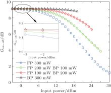
The coupled ODEs are solved numerically with the Predictor– Corrector method (PCM) based on four-step Adams– Bashforth method, [14] and the results of on– off gain versus input signal power are shown in Fig. 1. In the calculation, the total power of backward pump (BP) and forward pump (FP) is set to be 300 mW and the other parameters are set as follows: α s = 0.19 dB/km, α p = 0.3 dB/km, K = 2, Aeff = 80 μ m2, λ s = 1550 nm, λ p = 1455 nm, gR = 8.2858 × 10− 14 m/W, γ s = 1 × 10− 7 m− 1, in which the subscript s and p represent the signal and pump of the DFRA respectively. Additionally, the fiber length L adopted in the calculation is 100 km.
 | Fig. 1. Numerical results of on– off gain versus input signal power, obtained by PCM method. The inset shows the small signal gain. |
Although the ranges of results are limited by the convergence of the arithmetic, we can acquire the trend of each curve intuitively. In fact, in the BP scheme, the pump is injected into the opposite end of the fiber from the signal, where the signal power is quite low so that it cannot deplete the pump too much. In this situation, the gain is a little higher than that in the FP scheme, and also, the gain cannot decrease too dramatically with increasing input signal power. On the contrary, in the FP scheme, the pump is injected into the fiber at the same end as the signal, and the signal depletes the pump considerably. Hence, the gain is lower and the gain decreases dramatically with increasing input signal power.
Unfortunately, when Ps reaches the level, which can induce SBS in DFRA, part of the signal power is transferred to Brillouin Stokes light and depletes the Raman pump in different ways for BP and FP scheme respectively. Consequently, they have effects on the decrease of gain to different extents: for FP scheme, the Raman pump is injected at the end, where the Brillouin Stokes light is very strong. Therefore the SBS depletes the pump seriously and has a great effect on the gain saturation. On the contrary, SBS has little effect on the gain of backward-pumped DFRA due to the fact that the Raman pump is injected at the end where the power of Brillouin Stokes light is quite low. It is reasonable that the SBS threshold is taken as the gain saturation power. Therefore, the theoretical gain saturation power can be obtained by calculating the SBS threshold in DFRA.
The propagating equation for the Brillouin Stokes light is given by
where Ps, Pp, and PStokes are the powers of the signal, Raman pump, and Brillouin Stokes light respectively, gB is the Brillouin gain coefficient, and α Stokes is the attenuation coefficient of Brillouin Stokes light. By solving Eq. (2), the Brillouin Stokes light can be expressed as
where Ps(z) and Pp(z) are the power distributions of signal and Raman pump along the fiber. Given that the pump depletion (both Raman pump and Brillouin pump included) can be neglected before SBS occurs, the power of Brillouin Stokes light for a specific input signal power and Raman pump power can be achieved by substituting the results obtained from Eq. (1) into Eq. (3).
The SBS threshold condition can be defined as the input signal power when the power of Brillouin Stokes light is 10 dB higher than that of Rayleigh scattering which can also be obtained by solving Eq. (1). Based on the above method the theoretical gain saturation power is achieved. It should be noted that PStokes(L) = hν BΔ ν B, in which h = 6.626 × 10− 34 J· s is the Planck constant, ν B = 193.535 THz is the Brillouin Stokes light frequency, and Δ ν B = 50 MHz is the Brillouin gain bandwidth, other parameters in Eq. (3) are set to be gB = 2.3334 × 10− 11 m/W and α Stokes = 0.19 dB/km.
The effect of phase modulation on a single-frequency light is to add a series of side-bands beside the original frequency.[10] When the phase modulation frequency is large compared with the Brillouin gain bandwidth (usually 50 MHz), each side band can create its own SBS independently due to the non-overlapping gain spectra. According to this theory, the enhancement of SBS threshold is unrelated to the phase modulation frequency which can be expressed by[5, 11]

where Am is the phase modulation index, and Jn(Am) is the n-order Bessel function of the first kind. Figure 2 shows the curves of power spectrum versus phase modulation index which is useful when the enhancement of SBS threshold is calculated. It is emphasized that equation (4) is applicable only to the situation where the modulation frequency is high enough, while the overlap of the Brillouin spectra will make actual enhancement of SBS threshold smaller than that calculated by Eq. (4) when the phase modulation frequency is lower than the Brillouin gain bandwidth. Thus, it can be modified by simply introducing a factor related to the modulation frequency as follows:

where Q(ν m) can be called the correction factor that is related to modulation frequency and parameters of Brillouin gain spectrum. Theoretically, Q(ν m) decreases as the modulation frequency rises and approaches to zero gradually, because the overlapping ratio decreases as the modulation frequency rises. Since the SBS threshold is reasonably taken as the gain saturation power, the enhancement of gain saturation power can be expressed as

For convenience, the first items on the right-hand side of Eqs. (5) and (6) can be called the ideal values of the enhancements of SBS threshold and the gain saturation power respectively.
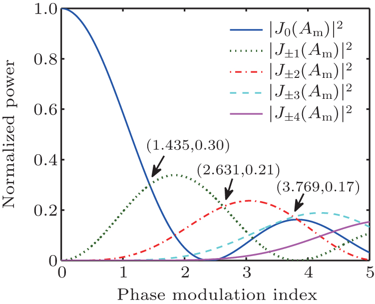 | Fig. 2. Curves of power spectrum versus phase modulation index. |
In order to validate the above theories, we conduct relevant experiments, and the experimental setup is shown in Fig. 3. A fiber laser (FL) is the signal source with the wavelength centered at 1550.03 nm and the output power being 7 dBm. The phase modulator is used to suppress SBS, and the modulation signal is provided by an arbitrary function generator (AFG). The combination of EDFA and variable optical attenuator (VOA) is adopted to increase the maximum input signal power, and overcome the shortage of the non-adjustable power of the FL as well. Consequently, the input signal power is tuned to − 5– 16 dBm rather than a constant value. The polarization scrambler (PS) is to eliminate the polarization correlation of the stimulated Raman scattering (SRS) with SBS, making the polarization factor K be 2. The function of the circulator is to observe the optical spectrum of the backscattering light by an optical spectrum analyzer (OSA) and to feed the signal into the DFRA at the same time. The pump light, from one single-modal 1455-nm laser diode (LD) with a maximum power of 470 mW, is split into two parts by an optical fiber coupler and injected into 100 km G.652 fiber by two 1450/1550 wavelength division multiplexers (WDM1 and WDM2) to provide forward and backward Raman pump respectively. The filter with 1nm bandwidth at the end of the DFRA is used to reduce the effect of ASE out of the signal linewidth on the signal power measured by the power meter (PM). PM1 is to monitor the input signal power, while PM2 is to monitor the output signal power.
 | Fig. 3. Experimental setup for different pump schemes. |
Based on the experimental setup above, some research is conducted on the relationship between the on– off gain and the input signal power for specific phase modulation parameters and in given pump schemes. It is necessary to emphasize that the total power of the forward and backward pump is also set to be 300 mW in the experiments and the attention is mainly concentrated on the forward-pumped DFRA, which is more typical for research.
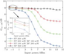
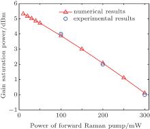
The curves of measured on– off gain of 100-km DFRA versus input signal power in four different pump schemes are shown in Fig. 4. Apparently, as for the BP scheme, the experimental curve and the numerical one shown in Fig. 1 are concordant very well: the on– off gains almost remain constant in a large input signal range. That is to say, SBS cannot make the backward-pumped DFRA saturated even if it occurs. On the contrary, the actual saturations for forward- and bi-directionally-pumped DFRAs take place at lower input signal powers than those in Fig. 1, which are about 0 dBm for 300 mW FP scheme, 2 dBm for 200 mW FP 100 mW BP scheme, and 4 dBm for 100 mW FP 200 mW BP scheme, respectively. These gain saturation powers are compared with the theoretical values in Fig. 5 and they show excellent agreement with each other.
 | Fig. 4. Experimental results of on– off gain versus input signal power. The inset shows the small signal gains versus input signal power. |
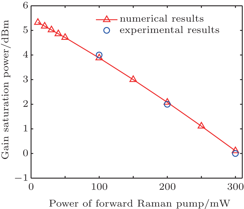 | Fig. 5. Theoretical and experimental plots of gain saturation power versus the power of forward Raman pump. Note: the numerical curve is not appropriate for the totally backward-pumped DFRA, owing to the fact that occurrence of SBS cannot make its gain saturate. |
Consequently, we conclude that SBS cannot make the backward-pumped DFRA saturated, which is more suitable for amplifying large signals, and a little higher gain can be obtained in this pump scheme as well. While SBS plays a significant role in the gain saturations of the forward- or bi-directionally-pumped DFRAs and phase modulation method used for suppressing SBS should be adopted to make DFRAs in these pump schemes applicable as far as the gain is concerned.
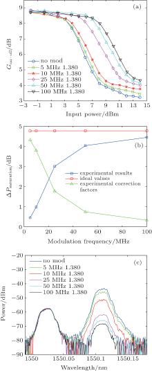
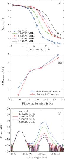
We conduct the experiment on the relationship of gain saturation and the phase modulation frequency to achieve the correction factor in Eq. (6), and the results are shown in Figs. 6(a) and 6(b), indicating that the enhancement of gain saturation power increases as the modulation frequency rises and approaches the ideal value gradually when the modulation frequency is high enough. Simultaneously, the correction factor decreases with increasing modulation frequency and approaches zero gradually eventually. This trend can be explained by the theory that when the modulation frequency is lower than the Brillouin gain bandwidth, the overlap of the Brillouin gain spectra generated by different phase-modulation-induced side-bands can strengthen the Brillouin Stokes light to some degree, thus the enhancement of the SBS threshold is lower than the ideal value, so is the enhancement of gain saturation power. Additionally, the lower the phase modulation frequency, the higher the overlapping ratio is and the larger the correction factor is. It is shown that for a modulation frequency of 25 MHz, the correction factor is 1.767 dB; when the phase modulation frequency reaches 100 MHz, the experimental enhancement of gain saturation power is 4.44 dBm that almost reaches the ideal value (the correction factor is 0.25 dB).
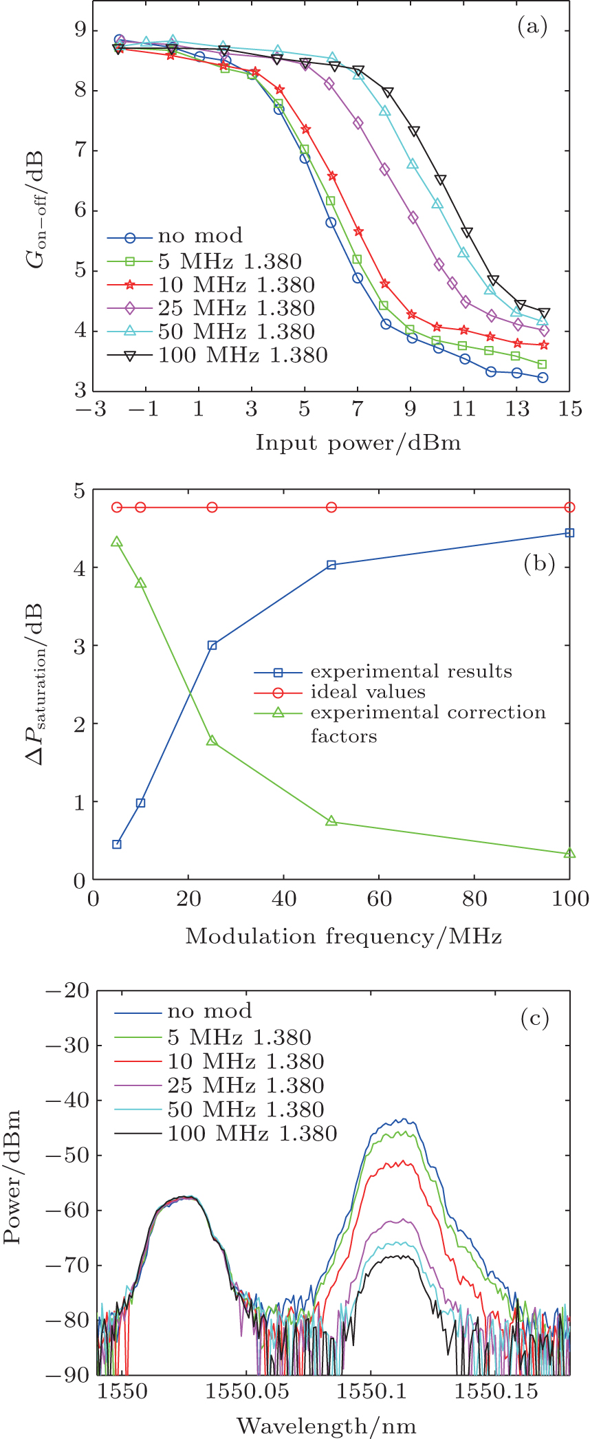 | Fig. 6. Results of index-fixed phase modulation experiments for forward-pumped DFRAs, showing (a) curves of on– off gain versus input signal power with various modulation frequencies and a fixed modulation index, (b) enhancements of gain saturation power versus phase modulation frequency with a fixed modulation index of 1.380, and (c) backscattering optical spectra with various modulation frequencies and a fixed modulation index (the input signal power is 3 dBm). |
Figure 6(c) shows the backscattering optical spectra for various modulation frequencies and a fixed modulation index of 1.380 with 3 dBm input signal power, in which the peak centered at about 1550.03 nm is the Rayleigh scattering light while the other centered at about 1550.11 nm is the Brillouin Stokes light with frequency downshifted about 11 GHz from the Rayleigh scattering light. It is observed that the phase modulation can suppress the Brillouin Stokes light a lot. Furthermore, the comparison of Fig. 6(a) with Fig. 6(c) indicates that when SBS takes place, the gain begins to decrease (the moment when the power of Brillouin Stokes light is 10 dB higher than that of Rayleigh scattering light is regarded as the indication of the occurrence of SBS, which is also adopted in the numerical simulation), that is to say, SBS is indeed an important factor causing gain saturation in the forward-pumped DFRA.
The curves of on– off gain versus input signal power through phase modulation with various modulation indexes and a fixed modulation frequency of 25 MHz for FP scheme are shown in Fig. 7(a), while the theoretical and experimental enhancements of gain saturation powers are shown in Fig. 7(b). The correction factor for a modulation frequency of 25 MHz is 1.767 dB which is obtained in Subsection 4.2, and by introducing such a correction factor into the ideal value, the experimental enhancements agree well with the theoretical values. Here the modified model proves reasonable.
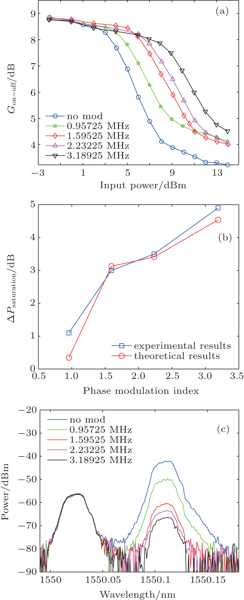 | Fig. 7. Results of frequency-fixed phase modulation experiments on the forward-pumped DFRA, showing (a) curves of on– off gain versus input signal power with various modulation indexes and a fixed frequency of 25 MHz, (b) enhancements of gain saturation power versus phase modulation index with a fixed modulation frequency of 25 MHz, and (c) backscattering optical spectra with various modulation indexes and a fixed frequency (the input signal power is 3 dBm). |
Moreover, the backscattering light optical spectra show the effect of phase modulation on the suppression of Brillouin Stokes light and indicate that the SBS plays a significant role in the gain saturation in the forward pumped DFRA.
In this paper, DFRAs without regard to SBS are simulated numerically, and the gain saturation powers with taking SBS into consideration are obtained theoretically by calculating SBS thresholds in DFRAs in various pump schemes. Experimental saturation powers show excellent agreement with theoretical ones, indicating that it is SBS that plays a significant role in the gain saturation. A saturation power as low as 0 dBm for the 300 mW forward-pumped DFRA is observed. Phase modulation is adopted in the forward-pumped DFRA to enhance gain saturation power. Experimentally, it is shown that the enhancement of gain saturation power increases as the phase modulation frequency rises, and approaches to the ideal value when the frequency is higher than Brillouin gain bandwidth (50 MHz). An enhancement of 4.44 dB is obtained by the phase modulation with a modulation frequency of 100 MHz and a modulation index of 1.380, which shows good agreement with the ideal value. It is found that the correction factor is 1.767 dB for a modulation frequency of 25 MHz. Through introducing the correction factor into the ideal value, the experimental enhancements can match the theoretical values. In a word, from the gain and the gain saturation points of view, BP scheme is the best choice when adopting Raman amplification, while phase modulation should be adopted to enhance the gain saturation power if the forward- or bi-directionally-pumped DFRAs are adopted. Instructionally, the parameters of the phase modulation can be chosen as follows: making the modulation frequency as high as possible and selecting the modulation index according to the ideal value presented in Eq. (6).
| 1 |
|
| 2 |
|
| 3 |
|
| 4 |
|
| 5 |
|
| 6 |
|
| 7 |
|
| 8 |
|
| 9 |
|
| 10 |
|
| 11 |
|
| 12 |
|
| 13 |
|
| 14 |
|