


Comparison of absorption–dispersion and optical bistability behaviors between open and closed four-level tripod atomic systems
[Karimi R., Asadpour S. H.† , Batebi S., Rahimpour Soleimani H.]
, Batebi S., Rahimpour Soleimani H.]
|
|


†Corresponding author. E-mail: S.Hosein.Asadpour@gmail.com
In this paper we investigate the optical properties of an open four-level tripod atomic system driven by an elliptically polarized probe field and compare its properties with the corresponding closed system. Our results reveal that absorption, dispersion, group velocity, and optical bistability of the probe field can be manipulated by adjusting the phase difference between the two circularly polarized components of a single coherent field and cavity parameters, i.e., the atomic exit rate from cavity and atomic injection rates.
Electromagnetically induced transparency (EIT) based on atomic coherence and quantum interference was discovered by Harris et al.[1] This phenomenon has led to many interesting phenomena such as lasing without inversion (LWI), [2] enhanced Kerr nonlinearity, [3] optical solitons, [4, 5] optical bistability and multi stability, [6– 10] slow light and fast light, [11, 12] and so on.[13, 14]
The control of light speed is highly desirable for many practical applications, such as in all-optical communication system quantum information processing, etc. It is well known that the group velocity of a light pulse can exceed the speed of light in a vacuum, leading to the superluminal light propagation, or it can slow down, leading to the subluminal light propagation. The subluminal light propagation and superluminal light propagation have been investigated extensively.[15– 21] Recently, many studies have been done on the switch from subluminal to superluminal light propagation, and vice versa, in an atomic medium. Switching from subluminal to superluminal light has been studied in a two-level atomic system in degenerate and non-degenerate cases.[15] It is shown that switching from subluminal to superluminal light propagation can be achieved with a relative phase between two weak probe fields.[22, 23]
The effects of spontaneously generated coherence (SGC)[19] on the absorption and dispersion profiles have been extensively investigated.[24– 27]
Optical bistability has been extensively studied both experimentally and theoretically due to its application in all-optical switching and optical transistors, and so on. For example, in a three-level V-type, [28] Λ -type, [29] and four-level N-type[30] have been investigated. In Ref. [31], Yuan et al. theoretically demonstrated the influence of dark and bright states on vacuum Rabi splitting (VRS) and optical bistability of the multiwave mixing (MWM) process in a collective four-level atomic cavity coupling system. They investigated the multi-dressed VRS and OB behavior of the zero and high-order transmitted cavity modes of MWM signals. Another paper[32] experimentally studied bright-state polaritons of FWM and six-wave mixing (SWM) signals through cascade nonlinear optical parametric amplification in an atom-cavity composite system.
In Ref. [33], Zhang et al. introduced a novel type of stable multi-component vector solitons consisting of two perpendicular four wave mixing (FWM) dipole components induced by electromagnetically induced gratings. They analyzed the formation and steering of the steady dipole solitons and their dynamical (energy transfer) effects. The dipole mode solitons of two FWM processes have horizontal and vertical orientations, respectively. In another interesting study, [34] by using the phase control between FWM and SWM channels in a four-level atomic system, temporal and spatial interferences between these two nonlinear optical processes have been demonstrated. It was shown that efficient and coexisting FWM and SWM signals can be produced in the same electromagnetically induced transparency window via atomic coherence.
In this paper, we investigate the optical response of an open four-level tripod atomic system driven by an elliptically polarized probe field and a linearly polarized control field. It is shown that by adjusting the cavity parameters and the relative phase difference between two circularly polarized components of the probe field and the frequency detuning of the probe field, one can control the absorption, dispersion, and bistable behaviors of the media. In an open atomic system, the levels of atomic system are allowed to exchange population with associated reservoir levels. These levels might, for example, be magnetic sublevels or hyperfine levels. The system is called open because the population that leaves the upper level does not necessarily enter the lower level. In this case the levels are assumed to acquire population at some controllable pump rates.
In the following section, we present the model and density matrix equation of motion. The results are discussed in Section 3, and the conclusion can be found in Section 4.
We consider an open four-level atomic system in configuration as depicted in Fig. 1. In this system the ground state | 1〉 is 5S1/2, F = 1, m = 0, the states | 2〉 and | 3〉 are 5S1/2, F = 2, m = − 1 and 5S1/2, F = 2, m = 1 degenerate Zeeman sublevels, respectively, and the excited state | 4〉 is the Zeeman sublevel corresponding to 5P3/2, F = 2, m = 0.
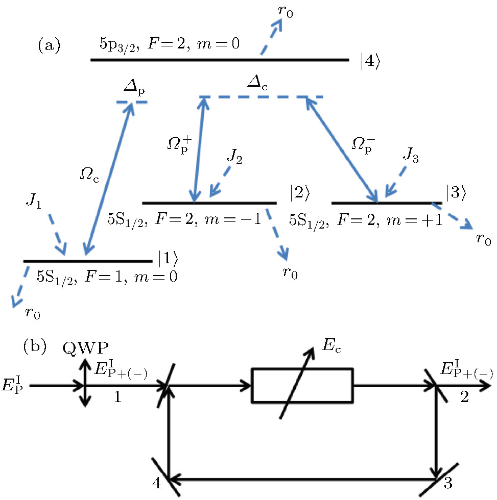 | Fig. 1. (a) A four-level atomic system in a tripod-type configuration. (b) Unidirectional ring cavity with an atomic sample of length L.   |
An elliptically polarized probe field with frequency ω p is used to create electric dipole transitions from | 4〉 to | 2〉 and | 4〉 to | 3〉 simultaneously. A probe field with electric field amplitude E0 after passing through the quarter-wave plate (QWP) becomes elliptically polarized and has been rotated by an angle θ . An elliptically polarized field can be decomposed into two mutually polarized components: 


The equations of motion for the density matrix elements for the tripod system under the rotating wave approximation and the electric dipole approximation become
In the above equations, Δ p = ω 43 − ω p = ω 42 − ω p and Δ c = ω 41 − ω c are the frequency detuning of the probe and control fields, where ω ij is the frequency deference between levels | i〉 and | j〉 . Γ ij is the spontaneous decay rate from level | i〉 and level | j〉 , and γ ij is the dephasing rate 
The set of equations can be used to calculate the response of the medium to the applied fields, by calculating the susceptibility of the probe field, which is defined as

where N is the atomic density number in the medium. The imaginary and real parts of χ p denote the absorption and dispersion coefficients for the probe field, respectively. If Im(ρ 42 + ρ 43) < 0, the probe field will be amplified; and if Im(ρ 42 + ρ 43) > 0, the probe filed will be attenuated.
The group velocity of the probe field is given by
where c is the speed of light in the vacuum and χ ′ (ω p) is the real part of χ p. The above equation implies that the steep positive dispersion can significantly reduce the group velocity. Moreover, the group velocity can be increased via a strong negative dispersion. If c/vg − 1 < 0, the group velocity of the radiation is larger than c, or it becomes negative, thus the propagation of radiation is superluminal, and the region c/vg − 1 > 0 corresponds to the subluminal propagation.
Now we consider a medium composed of the above described atomic system immersed in unidirectional ring cavity, as shown in Fig. 1(b). We assume that both mirrors 3 and 4 are perfect reflectors, and the intensity reflection and transmission of mirrors 1 and 2 are R and T (R + T = 1), respectively. The dynamic response of the elliptically polarized probe field governed by Maxwell’ s equation under slowly varying envelope approximation is

where P(ω p) = Nμ (ρ 42 + ρ 43) is the induced polarization. For a perfectly tuned cavity, the boundary condition in the steady state limit (∂ /∂ t → 0) is

where L is the length of the atomic sample, 

In the mean field limit, [35] using the boundary condition, we can describe the steady state behavior of elliptically polarized probe field by

where

are the normalized input and output fields, respectively, and C = Nω PLμ 2/(2ℏ ε 0cT) is cooperation parameter.
In this paper, all of the parameters are scaled by γ , which should be in the order of MHz for rubidium atoms. We assume Γ 41 = Γ 42 = Γ 43 = γ , Γ 32 = 0, Γ 31 = Γ 21 = 0.001γ , and all the other parameters are scaled by γ (γ = 6 MHz).
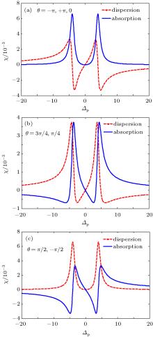
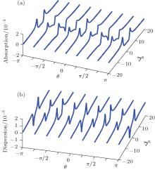
In this section, the effect of phase difference between the two circularly polarized components of a single coherent field on the absorption, dispersion spectrum, and group velocity of the probe field for different values of cavity parameters; i.e., the atomic exit rate from cavity and atomic injection rates will be studied. It is shown that optical properties of the system are very sensitive to the cavity parameters and the relative phase between applied fields. In Fig. 2, we plot the absorption (Fig. 2(a)) and dispersion (Fig. 2(b)) coefficient of the probe field (Im(χ p)) versus probe field detuning and phase difference for closed system (J1 = J2 = J3 = r0 = 0). It can be seen that by changing the phase difference between polarized probe light, the behaviors of absorption and dispersion can be changed. In this case, for θ = ± π /2, the probe absorption converts to the probe gain at some frequencies of the probe light. For the case of θ = 0, ± π , the absorption of the probe field at line center can be suppressed, and the atomic medium becomes transparent in the resonance region, and the slope of dispersion curve is positive at the area that corresponds to the subluminal propagation (Fig. 3(a)). It is found that by introducing a phase difference between electric field components (θ = π /4), the absorption and dispersion profiles drastically change. We observe that the phase difference leads to amplification of the probe field (negative absorption) for some probe detuning (Fig. 3(b)). The gain increases with increasing magnitude of phase to θ = π /2 (Fig. 3(c)), so the probe field can be amplified for appropriate values of phase difference without applying an incoherent pumping field to the system. By changing the magnitude of θ , the slope of the dispersion curve changes. In order to further explicitly understand the dependence of the absorption (gain) spectra of the probe field on the phase difference, the probe absorption as a function of the probe detuning and phase difference is plotted in a 3-dimensional graph (Fig. 4). The regions in which the probe field is amplified are marked in dark blue.
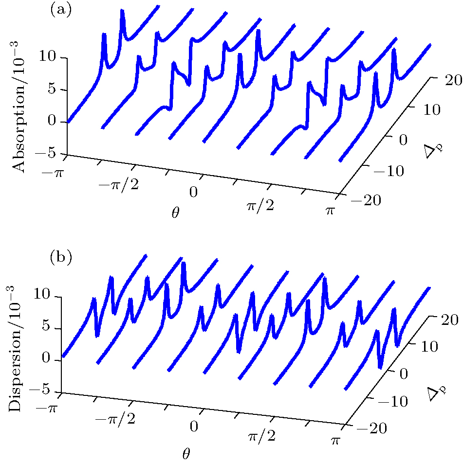 | Fig. 2. (a) Probe absorption and (b) probe dispersion versus the probe detuning and θ for closed system. Ω p = 0.01γ , Ω c = 4γ , Δ c = 0, Γ 41 = Γ 42 = Γ 43 = γ , Γ 32 = 0, Γ 31 = Γ 21 = 0.001γ . |
 | Fig. 3. Probe absorption (solid line), probe dispersion (dashed line) versus the probe detuning Δ p for closed system at (a) θ = 0 ± π , (b) θ = π /4, 3π /4, (c) θ = ± π /2. Other parameters are the same as those in Fig. 2. |
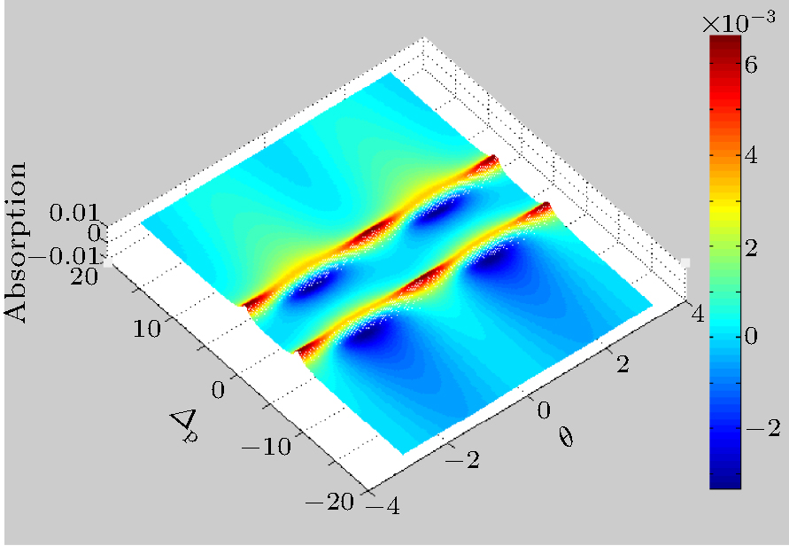 | Fig. 4. Probe absorption versus the probe detuning and θ . The other parameters are the same as those in Fig. 2. |
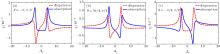
In the following, we analyze the influence of phase difference on the absorption, dispersion, and group velocity in an open tripod-type four-level atomic system (J1 = J2 = J3 = 0.1γ ). The numerical calculation result shows that, in this case, the optical properties of the probe field are also sensitive to phase difference between two components of probe field. From Fig. 5, we can find that the absorption spectrums at given phase difference completely convert to amplification. Therefore, the medium behaves as a gain media. For the case of θ = 0, ± π , the absorption of probe field at the line center is negative, and so the probe field can be amplified (Fig. 6(a)), while in a closed system there is no gain in this condition. Figures 6(b) and 6(c) show the absorption and dispersion behaviors of the probe field for θ = 3π /4, π /4 and θ = ± π /2, respectively.
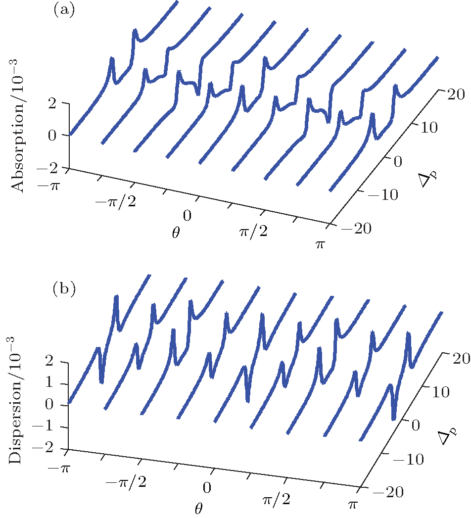 | Fig. 5. (a) Probe absorption and (b) probe dispersion versus the probe detuning and phase difference θ for an open system. J1 = J2 = J3 = 0.1γ . Other parameters are the same as those in Fig. 2. |
 | Fig. 6. Probe absorption (solid line), probe dispersion (dashed line) versus the probe detuning Δ p for an open system J1 = J2 = J3 = 0.1γ at (a) θ = 0, ± π , (b) θ = π /4, 3π /4, (c) θ = ± π /2. Other parameters are the same as those in Fig. 2. |
As clearly seen from the above figures by changing the phase difference, the amount of gain in an open system is changed. Hence, by applying the appropriate phase difference between the two components of the probe field, further amplification of the probe field in system can be observed. As a closed system, in this case, the slope of the dispersion curve is dependent on the phase difference, and so the group velocity of the probe field will also change with the change of the phase difference.
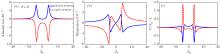
In Figs. 7– 9 we demonstrate the optical properties of an open four-level tripod atomic system driven by an elliptically polarized probe field, and compare its properties with the corresponding closed system. Our results reveal that the absorption, dispersion, and group velocity of probe field can be manipulated by adjusting the phase difference between the two circularly polarized components of a single coherent field and cavity parameters; i.e., the atomic exit rate from cavity and atomic injection rates.
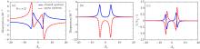
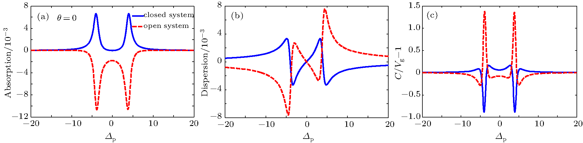 | Fig. 7. (a) Probe absorption, (b) dispersion, and (c) group velocity versus the probe detuning Δ p for closed (solid line) and open (dashed line) system J1 = J3 = 0.1, J2 = 1.7γ at θ = 0. Other parameters are the same as those in Fig. 2. |
 | Fig. 8. (a) Probe absorption (b) dispersion, and (c) group velocity versus the probe detuning Δ p for closed (solid line) and open (dashed line) system J1 = J3 = 0.1, J2 = 1.7γ at θ = π /4. Other parameters are the same as those in Fig. 2. |
 | Fig. 9. (a) Probe absorption (b) dispersion, and (c) group velocity versus the probe detuning Δ p for closed (solid line) and open (dashed line) system J1 = J3 = 0.1, J2 = 1.7γ at θ = π /2. Other parameters are the same as those in Fig. 2. |
The numerical calculation result (Fig. 7(a)) shows that when two components of the probe field are parallel, i.e., θ = 0, in the absence of atomic exit rate (closed system), the medium experiences absorption; while in the presence of these parameters (open system, J1 = J3 = 0.1, J2 = 1.7γ ) the probe absorption converts to negative values with two deeps of equal amplitude, where they are placed symmetrically with respect to the resonant region in Δ p = ± Ω c. Hence, an amplification of the probe field (probe gain) can be obtained. Note that the amount of gain is sensitive to cavity parameters (compare Figs. 6 and 7). The behavior of dispersion and group velocity are also shown in Figs. 7(b) and 7(c), respectively. It is found that when θ = 0, the cavity parameters affect the dispersion profile. In this case the dispersion slope at the line center is positive for closed system that corresponds to the subluminal light propagation, while for the open system the slope of dispersion curve is negative, relating to the superluminal light propagation. As a result, we can switch subluminal to superluminal light propagation with an appropriate choice of cavity parameters; i.e., atomic exit rate from cavity and injection rates. When θ = π /4 and θ = π /2 in both open and closed systems, the probe field can be amplified. Note that the gain in the open system is larger than that in the closed system (Figs. 8(a) and 9(a)), and in contrast to the previous case (θ = 0), there is no symmetry in the absorption curve for these cases. The dispersion curve and the group velocity of the probe field as a function of probe detuning for closed and open system are depicted in Figs. 8 and 9. It is clear from figures that the optical properties of system, i.e., the absorption, dispersion, and group velocity of probe field, are sensitive to cavity parameter and phase difference. Hence, we can switch the system from a positive absorption to negative absorption, also from subluminal to superluminal light propagation with an appropriate choice of θ , Δ p, and cavity parameters.
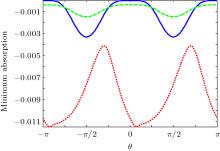
The minimum absorption as a function of the phase difference for different values of cavity parameters is plotted in Fig. 10. As shown in this figure, the minimum absorption (maximum gain) occurs at θ = ± π /2, for both closed system (solid line) and open system with cavity parameters: J1 = J2 = J3 = 0.1γ (dashed line). The gain for the open system is larger than that for the closed system at − π /4 < θ < π /4; while for − 3π /4 < θ < − π /4 and π /4 < θ < 3π /4, the gain for closed system is larger; for the rest of phase difference, the gain for open system is larger. By changing the cavity parameters to J1 = J2 = 0.1γ , J2 = 1.7γ , the minimum absorption for all values of θ decreases, so the gain increase and its value is larger than that for closed system (dotted line). Thus, appropriate choice of phase difference θ and cavity parameters is useful in optimizing and controlling the amount of gain for the four-level tripod-type system.
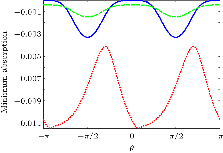 | Fig. 10. The minimum absorption as a function of phase difference for different values of cavity parameters for closed system (solid line) J1 = J2 = J3 = 0.1γ (dashed line) and J1 = J2 = 0.1γ , J2 = 1.7γ (dotted line). The other parameters are the same as those in Fig. 2. |
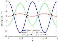
Finally, we investigate the influence of phase difference between two components of probe field on bistability in closed and open systems. We find that the threshold and the width of the bistable region can be manipulated by the relative phase difference. The output field versus input field for different values of θ for closed system and open system with different values of cavity parameters are depicted in Figs. 11(a)– 11(c).
 | Fig. 11. Output intensity versus input intensity for different values of θ for (a) closed system (b) open system with cavity parameter J1 = J2 = J3 = 0.1γ , (c) J1 = 0.1γ , J2 = J3 = 0.2γ when Δ p = 1.5γ . The other parameters are the same as those in Fig. 2. |
When θ = π /4, 
In summary, we have investigated the optical properties of an open four-level tripod atomic system driven by an elliptically polarized probe field and we have compared its properties with the corresponding closed system. We have found that the phase difference between the applied fields can affect the absorption, dispersion, group index, and intensity threshold of optical bistability.
| 1 |
|
| 2 |
|
| 3 |
|
| 4 |
|
| 5 |
|
| 6 |
|
| 7 |
|
| 8 |
|
| 9 |
|
| 10 |
|
| 11 |
|
| 12 |
|
| 13 |
|
| 14 |
|
| 15 |
|
| 16 |
|
| 17 |
|
| 18 |
|
| 19 |
|
| 20 |
|
| 21 |
|
| 22 |
|
| 23 |
|
| 24 |
|
| 25 |
|
| 26 |
|
| 27 |
|
| 28 |
|
| 29 |
|
| 30 |
|
| 31 |
|
| 32 |
|
| 33 |
|
| 34 |
|
| 35 |
|