


Spin pumping through magnetic impurity effect
[Deng Wei-Yina) † , Sheng Lia), b)  , Xing Ding-Yu
a), b) ]
, Xing Ding-Yu|
|


†Corresponding author. E-mail: shengli@nju.edu.cn
*Project supported by the State Key Program for Basic Research of China (Grant Nos. 2015CB921202, 2014CB921103, 2011CB922103, and 2010CB923400), the National Natural Science Foundation of China (Grant Nos. 11225420, 11174125, and 91021003), and the Priority Academic Program Development of Jiangsu Higher Education Institutions.
We propose a simple adiabatic quantum spin pump to generate pure spin current. The spin pump is driven by an ac gate voltage and a time-dependent magnetic impurity potential. It is found that the total pumped spin per cycle exhibits oscillations, whose magnitude decays exponentially with changing strength of the impurity potential. The proposed method may be useful for spintronic applications.
Soon after the integer quantum Hall (IQH) effect was discovered in 1980, [1] Thouless et al. showed that the IQH state can be classified by a topological invariant, the TKNN number, [2] or the Chern number. Then Thouless, [3] and Niu and Thouless[4] also established a general relation between the Chern number and the charge pump, which can generate a dc current by periodically and slowly modulating some parameters in a quantum system under zero bias. The Thouless charge pump suggests a way to observe the topological-invariant Chern number. Recently, due to the discovery of the quantum spin Hall (QSH) effect, [5, 6] the Z2 index[7] and spin Chern number[8, 9] have been proposed as the unconventional topological invariants to describe the QSH systems. Correspondingly, the Z2 spin pump [10] and spin Chern pump[11, 12] are proposed to realize these topological invariants. The essential difference between these two types of spin pumps is that the time-reversal symmetry is necessary for the Z2 pump, but the spin Chern pump relies on the electron bulk band topology alone.
Although the adiabatic pump was originally suggested for realizing the topological invariant, it has been extensively studied in recent decades. Based on the Berry phase theorem associated with the scattering matrix, [13– 15] the charge and spin pumps have been proposed for a variety of mesoscopic systems, such as an open quantum dot, [16] superconductor, [17] graphene, [18] quasicrystals, [19] systems with spin– orbit coupling, [20, 21] one-dimensional optical lattice, [22] interacting quantum systems, [23, 24] helimagnet heterostructures, [25] etc. The quantum pumps provide broad applications in nanometer devices. Niu suggested that the charge pump can be used as a standard for charge current, [26] and a similar device was realized in an acoustoelectric system later.[27] Das and Shpitalnik proposed a model to pump fractional charge.[28] The spin pumps can be used as spin batteries, and produce pure spin current in spintronic devices.[29] Mucciolo et al. proposed a spin pump in an open quantum dot to generate spin current, which was realized experimentally soon after Refs. [30] and [31]. Lin et al. demonstrated that a spin pump can generate pure spin current in a quantum channel with both static Rashba and Dresselhaus spin– orbit interactions by using the Floquet scattering method.[32] Zhang et al. found that pure spin current can be generated in monolayer graphene based on adiabatic quantum pumping.[33, 34] Since most of the above proposals for spin pumps have not been realized experimentally, it is still desirable to explore other methods that might be easier to implement.
In this paper, we propose an adiabatic spin pump, which is composed of a zigzag atomic chain and subjected to a spatially-varying magnetic field and an ac gate voltage. A time-dependent magnetic impurity potential is exerted between the pump and the electrode, which may be realized by shifting a magnetic probe periodically. We show that pure spin current can be pumped from this setup into a nonmagnetic electrode. The effect of the magnetic impurity potential on the spin pumping is analyzed in detail. The ac gate voltage and the shifting magnetic probe are the driving forces in the present spin pump, which may be relatively easy to manipulate experimentally.
In the next section, we present the model Hamiltonian and theoretical calculation. In Section 3, the calculated results are discussed. The final section contains a summary.
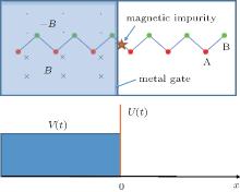
We consider a zigzag atomic chain, each unit cell containing two inequivalent sites, A and B. The system is divided into two parts, the pump part and the electrode as illustrated in Fig. 1. A non-uniform magnetic field is applied to the pump part in such a manner that the A and B sites experience opposite Zeeman fields. Experimentally, this may be achieved by depositing the atomic chains on the substrate of an antiferromagnetic insulator. Besides, such Zeeman fields may be more easily realized in the systems of fermionic cold atoms.[35] An oscillating gate voltage is also applied to the pump part in the plane of the atomic chain, which provides a time-dependent potential for the electron. As a consequence, the Hamiltonian of the pump part can be written as
Here, 

where vF = t0a0/ħ is a Fermi velocity and a0 is the lattice constant, σ y(z) are the Pauli matrices associated with the AB sublattices.
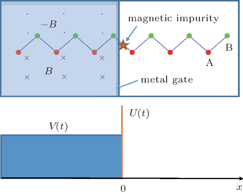 | Fig. 1. Schematics of a one-dimensional spin pump, showing that there exists a magnetic impurity between two parts. The oscillating potential U(t) is made by a microscope probe above the impurity with vertical up-and-down movement. The oscillating voltage V(t) is applied by a metal gate. |
Between the pump and lead, we assume that there exists a time-dependent magnetic impurity potential U(t)sx, which varies with time as U = U0 + Us cos (ω t + θ ), where θ is the phase difference between the two time-dependent potentials. A possible experimental realization of this potential is to locate a magnetic probe of microscope in proximity to the atomic chain and changes the distance between them periodically. We set the Fermi level to be EF = V0 and g > Vs, to make sure that EF is inside the band gap of the pump. The wave function inside the pump decays exponentially. The boundary condition for the wave functions is given by[11]

where 

where χ = χ 0 cos ω t, χ 0 = Vs/g and χ 0 < 1. It is easy to check | r↑ ↑ | 2 + | r↓ ↑ | 2 = 1. Similarly, by considering the case where the incident electron has a spin antiparallel to the z axis, the reflection coefficient amplitudes can be obtained as 

In the adiabatic regime, the pumped 2 × 2 tensor current 

where T = 2π /ω is the period of the pump, 

Using the expression for the scattering matrix, the pumped charge and spin can be written more specifically as
and


By use of the symmetry relations r↑ ↓ = r↓ ↑ and 


Because r↓ ↑ is purely imaginary from Eq. (4), 

where 

Throughout this paper, we set the Fermi energy to be EF = V0 and g > Vs. In the numerical calculations, the phase difference θ between the two time-dependent potentials is set to be π /2, where the pumping rate of spin is maximized. The pumped spin Δ sz (χ 0, U0, Us) is a function of ratio χ 0, static potential U0 and modulated potential Us of the magnetic impurity.
 | Fig. 2. Variations of pumped spin Δ sz with ratio χ 0 of driving gate potential to Zeeman splitting energy for some different values of the static potential of the magnetic impurity. The modulated potential of the magnetic impurity is set to be Us = 1. |
While the present model is somewhat similar to the topological spin pump, [10, 11] the spin pumping effect in this model is not related to a topological invariant. In the adiabatic limit, the spin Chern number C± for Hamiltonian Eq. (2) can be defined in a standard way, [39– 41] and one can obtain C± = 0 on the torus of kx ∈ [− ∞ , ∞ ] and t ∈ [0, T]. In this sense, the system is topologically trivial. As shown in Fig. 2, the magnitude of pumped spin relies sensitively on the choice of the parameters, and cannot reach the quantized value ħ , i.e., Δ sz ∈ (− ħ , ħ ) from the numerical simulation. From Fig. 2, we observe that the magnitude of the pumped spin increases with increasing the parameter χ 0 = Vs/g. This is because nonzero Vs is a driving force for the spin pumping, and so the increasing of its relative strength with respect to the static Zeeman field g favors the spin pumping. As observed in Eq. (11), the pumped spin is a sine function of 2U0, indicating that the magnitude and sign of the spin pumped per cycle depends sensitively on the static potential of the magnetic impurity. Indeed, from Fig. 2, we see that the pumped spin has a positive sign for U0 = 1, vanishes for U0 = π / 2, and switches to a negative sign for U0 = 2.
 | Fig. 3. Pumped spin Δ sz versus the static potential U0 of impurity. The ratio of driving gate potential to Zeeman splitting energy is χ 0 = 0.9. The modulated potential of impurity is Us = 1.5t0. |
In Fig. 3, the pumped spin is plotted as a function of the static potential U0 of the magnetic impurity. The result is consistent with the analytical expression given in Eq. (11), where the pumped spin is a sine function of U0 with a period π . This is a resonance effect of the pumped spin with the magnetic impurity. The resonance effect originates from the boundary condition at the magnetic impurity, which makes the reflection coefficient r↑ ↑ a cosine function of the static potential of the magnetic impurity.
We plot the pumped spin as a function of the oscillating potential Us of the magnetic impurity, for three different values of χ 0, in Fig. 4. We find that with increasing Us, the pumped spin oscillates and its magnitude decays exponentially. This is an intriguing feature that the magnitude of the pumped spin decreases with increasing the driving magnitude. It is natural to see that the magnitude of the pumped spin increases with increasing χ 0, the ratio between the driving gate potential and Zeeman energy. Moreover, in Fig. 4 we see that varying χ 0 changes the magnitude of the oscillations of the pumped spin, but nearly does not lead to any phase shift of the oscillations.
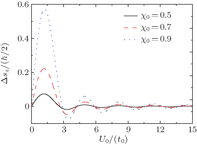 | Fig. 4. Variations of pumped spin Δ sz with modulated potential Us of the magnetic impurity for some different values of ratio χ 0. The static potential of the magnetic impurity is set to be U0 = 2t0. |
In summary, we study a one-dimensional quantum spin pump device. By adiabatically modulating an ac gate voltage and a time-dependent magnetic impurity potential, a pure spin current can be pumped into a nonmagnetic lead. We find that the spin pump is topologically trivial, and the value of pumped spin is not quantized. The pumped spin is a sine function of the static part of the magnetic impurity potential, and exhibits oscillations, whose magnitude decays exponentially with increasing the strength of the oscillating part of the magnetic impurity potential.
| 1 |
|
| 2 |
|
| 3 |
|
| 4 |
|
| 5 |
|
| 6 |
|
| 7 |
|
| 8 |
|
| 9 |
|
| 10 |
|
| 11 |
|
| 12 |
|
| 13 |
|
| 14 |
|
| 15 |
|
| 16 |
|
| 17 |
|
| 18 |
|
| 19 |
|
| 20 |
|
| 21 |
|
| 22 |
|
| 23 |
|
| 24 |
|
| 25 |
|
| 26 |
|
| 27 |
|
| 28 |
|
| 29 |
|
| 30 |
|
| 31 |
|
| 32 |
|
| 33 |
|
| 34 |
|
| 35 |
|
| 36 |
|
| 37 |
|
| 38 |
|
| 39 |
|
| 40 |
|
| 41 |
|