
Indenter size effect on the reversible incipient plasticity of Al (001) surface: Quasicontinuum study
[Tang Dana), b) , Shao Yu-Fei†b)  , Li Jiu-Hui
c) , Zhao Xingc) , Qi Yang‡a) ]
, Li Jiu-Hui]
|
|


†Corresponding author. E-mail: yfshao@alum.imr.ac.cn
‡Corresponding author. E-mail: qiyang60@sohu.com
*Project supported by the National Natural Science Foundation of China (Grant No. 51172040), the National Basic Research Program of China (Grant No. 2011CB606403), and the General Project of Scientific Research from Liaoning Educational Committee, China (Grant No. L2014135).
Indenter size effect on the reversible incipient plasticity of Al (001) surface is studied by quasicontinuum simulations. Results show that the incipient plasticity under small indenter, the radius of which is less than ten nanometers, is dominated by a simple planar fault defect that can be fully removed after withdrawal of the indenter; otherwise, irreversible incipient plastic deformation driven by a complex dislocation activity is preferred, and the debris of deformation twins, dislocations, and stacking fault ribbons still remain beneath the surface when the indenter has been completely retracted. Based on stress distributions calculated at an atomic level, the reason why the dislocation burst instead of a simple fault ribbon is observed under a large indenter is the release of the intensely accumulated shear stress. Finally, the critical load analysis implies that there exists a reversible-irreversible transition of incipient plasticity induced by indenter size. Our findings provide a further insight into the incipient surface plasticity of face-centered-cubic metals in nano-sized contact issues.
As the sizes of devices in electromechanical systems shrink to micro- and nano-scales, small mechanical contacts become significant for the performances of those tiny equipments.[1– 6] Understanding the deformation mechanisms of surface atoms in the contact area is important to develop such systems. One of the main concerns about the mechanical behavior of material surface is the incipient plasticity, which is commonly studied by using nanoindentation tests.[7, 8] For example, the effects of crystal orientation, [9, 10] surface roughness, [11– 14] heterogeneous interface, [15– 17] and grain boundary[18– 20] on the incipient plasticity of face-centered-cubic (FCC) metals have been widely studied by both experimental measurements and atomistic simulations.
Recently, some uncommon reversible dislocation processes of the incipient plasticity of stepped Au (111) surfaces have been revealed by nanoindentation experiments.[21] It is deduced that most of these dislocations are metastable under stress and evanesce when the indenting tip is retracted. However, the detailed information on an atomic level underneath the surface is not easily visualized by experimental tests. Later, molecular dynamics (MD) simulations have been performed to study the reversible plasticity of Cu atomically flat and stepped (111) surfaces.[22] These MD results suggest that it is the occurrence of cross-slip that marks the end of the reversible plasticity. Motivated by these findings, we have performed the atomistic simulations on the reversible plasticity of Al (001) surface.[23] Like the above MD simulations, our results show that multiple slip systems are activated when irreversible plastic deformation occurs. Thus, the atomistic mechanisms of reversible surface plasticity of FCC metals have been systematically investigated both experimentally and computationally. However, there are still some issues remaining to be studied.
In this work, the indenter size effect on the reversibility of incipient surface plasticity is studied. To our knowledge, the effect of indenter size on the incipient plasticity of metal surfaces is originally revealed by Knap and Ortiz.[24] An indenter in experimental size is used in their multiscale simulations. Later, Lu et al. suggested that critical load can be influenced by contact position, when a Cu thin film is punched by a small indenter with a diameter of 18 nm.[25] These studies imply that indenter size effect cannot be ignored in nano-sized contacts, and motivate us to extend the size-effect research to the reversible surface plasticity. Usually, the typical size of indenter in experimental tests is on the order of 50 nm– 1000 nm, [7] much larger than those in atomistic simulations. For example, the dependence of hardness of nickel on grain size has been studied by an indenter with a radius of 200 nm; [18] the onset of plasticity of polycrystalline Al has been studied by an indenter with a radius of 100 nm; [26] the incipient plasticity of stepped Au surface has been investigated by an indenter with a radius of 45 nm.[21] However, in recent years the size of indenter can decrease into atomic scale. An indenter with a radius of 26 nm is used to study a graphene sheet most recently.[27] Hence, our findings in this work can provide some theoretical and computational guidance for relevant experimental tests on the reversible incipient surface plasticity of metals.
Nanoindentation processes on Al (001) surface with indenters in different sizes are simulated by using the quasicontinuum (QC) method[28– 30] in the present work. As we mentioned before, the QC method is able to study local physical phenomena in models, thus spanning several length scales, and obtain the same results as classical atomistic simulations with a fraction of the computational cost.[31– 35] Owing to this virtue, nanoindentation simulations with indenters in experimental scale can be performed. The rest of this paper is organized as follows. In Section 2, the basic principle of the QC method is briefly introduced and the details of the computational procedure are presented. In Section 3, the main results of the present work are displayed. Indenter size effects on the load-displacement response are observed. Finally, the simulation results are analyzed in Section 4.
As a multiscale method, the QC method is able to couple atomistic simulation with a continuum description. Atoms of a crystal in a QC model can be categorized as local and non-local, according to a criterion derived from deformation gradient. The displacements and energies of nonlocal atoms are explicitly calculated by standard lattice statics method, while the local atoms are approximately treated by Cauchy– Born rule and finite element techniques. Empirical interatomic potentials, such as the embedded atom method (EAM) potential, are usually used to describe all the atoms in a QC sample.[36] Plastic deformation can be revealed by observing the movements of nonlocal atoms, while elastically strained regions can be coarsened by local atoms. After each loading step, the equilibrium configuration of the entire system can be established through the minimization of the total energy with respect to atomic position. More technical details about the QC method can be found in the review article.[37]
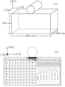
The QC model for nanoindentation on an Al single crystal is the same as that used in our previous work, [23] and schematically presented in Fig. 1(a). The size of the crystal is 200 nm× 100 nm× 0.286 nm, and periodical boundary condition is applied along the out-of-plane direction. Initially, a cylindrical rigid indenter is placed in the center of the top surface. The region just underneath the indenter is filled with nonlocal atoms, while the region away from the indenter is approximately represented by local atoms and triangular meshes as shown by Fig. 1(b). The indenter can be regarded as an external repulsive potential interacting with surface atoms, which is expressed as[38]

where A is a force constant, R is the radius of the indenter, and H(R− r) is the step function, r is the distance between an atom and the indenter axis, H(R− r) = 1, if r< R, otherwise, H(R− r) = 0. In the present calculations, A = 1.602 μ N/nm2. The atoms at bottom and lateral surfaces are kept fixed, while the positions of all other atoms can be adjusted by energy relaxation. The indentation proceeds in displacement-control in steps of 0.02 nm. After each loading step, the total energy is minimized until the sum of out-of-balance forces over the entire system is less than 1.602× 10− 3 nN. All the mechanical properties of atoms in the crystal are given by the EAM potential proposed by Voter and Chen.[39] To clarify the indenter size effect on the incipient surface plasticity, two indenters with the radii R = 2.5 nm and R = 17.5 nm are used respectively.
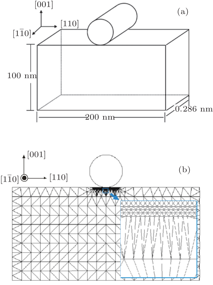 | Fig. 1. The QC model for nanoindentation on a single crystal Al. (a) Schematic illustration, (b) atomistic and continuum regions, enlarged view of atomistic region and the hand-shaking zone are in the lower right corner. |
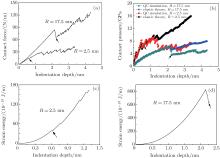
The load-displacement curves obtained from the present simulations are presented in Fig. 2(a). The contact force is applied by an indenter and can be calculated as follows:

where Z represents all atoms contacting the indenter, and Pi is the out-of-balance force on the i-th atom in this contact zone, projected along the indentation direction, dthick (= 0.286 nm) is the thickness of the crystal along the 
The two contact force curves are clearly much different in profile. Both curves rise smoothly up to the first drop, as indicated by the black arrows. However, the curve continues to climb up with only a few slight drops for the 2.5-nm-indenter. The slopes of these curve segments after first drop seem to be the same as that in the first stage. For the 17.5-nm-indenter, no zigzag appears before the first drop, which seems quite dramatic. It is suggested that the first force drop indicates the onset of incipient plasticity.[32, 40] Hence, the distinction between the two curves in Fig. 2(a) implies that there are different plastic mechanisms under the two indenters.
 | Fig. 2. Responses under two indenters. (a) Contact force, (b) contact pressure, (c) strain energy, R= 2.5 nm, (d) strain energy, R= 17.5 nm. Black arrows in these subfigures indicate the onsets of plasticity. |
According to the applied force P, the contact pressure can be determined at each step as

where a is half the width of the projected contact area at each indentation step. Besides, according to continuum mechanics theory, the indentation depth of an elastically deformed crystal in contact with a rigid cylinder can be calculated from[41]

Substituting this into Eq. (3) gives the contact pressure for the Al (001) surface as follows:[19]
where a is defined as the previous one, δ means indentation depth, t is the height of the Al crystal along the indentation direction, E and ν are the Young’ s modulus and Poisson’ s ratio along the [001] direction of Al crystal. In the present simulations, a varies with indentation depth, t is equal to 100 nm; E and ν can be obtained from the elastic constants C11, C12, and C44 as[42]


Based on the QC predictions, C11, C12, and C44 are 102 GPa, 61.3 GPa, and 31.2 GPa respectively, close to the experimental results 114 GPa, 61.9 GPa, and 31.6 GPa. As a consequence, the values of E and ν are approximately 56 GPa and 0.34.
The contact pressures from QC simulations and theoretical predictions are plotted in Fig. 2(b). In fact, the simulation results do not coincide with the theoretical predictions, unless an empirical scaling parameter η is applied. The physical meaning of the scaling parameter has been explained in our previous work.[23] For the 2.5-nm-indenter, η = 0.825; for the 17.5-nm-indenter, η = 0.685. Each loading step corresponding to the first force drop in Fig. 2(a) is indicated by a black arrow. Note that the contact pressures under the 2.5-nm-indenter still agree with the elastic predictions very well, even the incipient plasticity has occurred. For the 17.5-nm-indenter, the values of contact pressure are much lower than the theoretical results, once the incipient plasticity starts to proceed.
The drops in Fig. 2(b) should be explained carefully, especially for those in elastic stage terminated by black arrows. According to Eqs. (3) and (4b), the contact pressure is influenced by contact length, which undergoes a stepwise development under a small indenter as the number of atoms contacted by the indenter increases discontinuously.[23, 32] As a result, a few drops are observed in the elastic stages of the two contact pressure curves. It is due to the same reason that the elastic segment of contact pressure curve under the 17.5-nm-indenter is much smoother, i.e. the number of contacted atoms increases more continuously under a larger indenter. In fact, figures 2(c) and 2(d) indicate that no energy is dissipated in the elastic stages. In the plastic stages behind the black arrows for both indenters, the drops in Fig. 2(b) are determined by both contact length increase and strain energy dissipation, and the simulation results start to deviate from the elastic theoretical predictions in the late stages of the contact pressure curves. Note that only the strain energies prior to severe plastic deformation are plotted in Figs. 2(c) and 2(d), and the values of strain energy are given in Joule per meter length along the indenter axis, since the geometrical configuration of the model is quasi-two-dimensional.
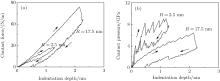
The contact forces and pressures during the withdrawal processes of two indenters are given in Fig. 3. Note that the maximum indentation depth is chosen differently for the two indenters. However, both of them correspond to the incipient stages of plasticity. After full retraction, the residual indentation depth under the 2.5-nm-indenter is reduced to zero, while the residual indentation depth under the 17.5-nm-indenter remains 0.46 nm. The nonzero residue depth means that the surface is permanently damaged, i.e., the incipient plasticity is irreversible.
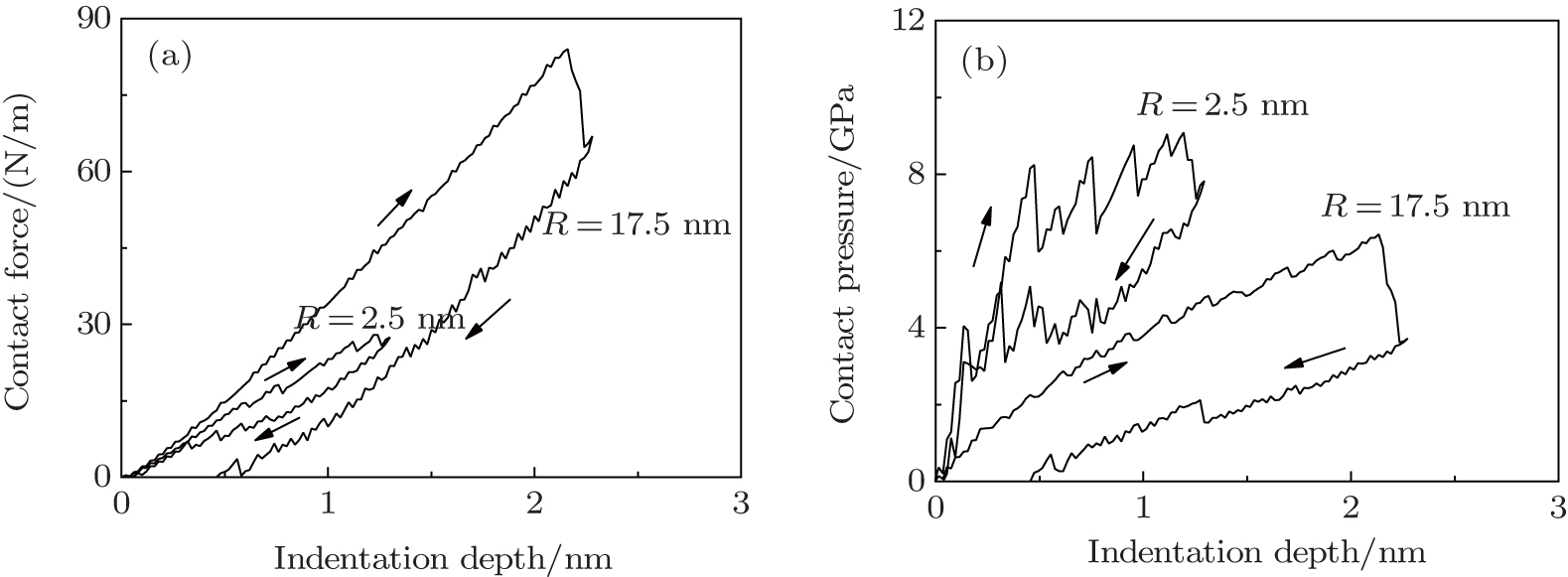 | Fig. 3. Loading– unloading processes. (a) Contact force, (b) contact pressure. |
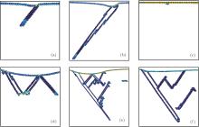
To reveal the atomistic mechanisms of the distinction between the 2.5-nm and 17.5-nm curves in Fig. 3, the structural evolution processes of atoms under the two indenters are visualized by the software ‘ Atomeye’ [43] combined with the central symmetry parameter analyzing method.[38] The activities of atoms corresponding to onsets of plasticity, maximum indentation depths in Fig. 3, and the full withdrawal of the indenters are displayed in Fig. 4. Only surface and defected atoms are shown and automatically colored by ‘ Atomeye’ , other atoms are invisible. Clearly, the incipient plasticity under the 2.5-nm-indenter is triggered by the nucleation of a stacking fault ribbon, which is generated by the nucleation and slipping of a partial Shockley dislocation. As the indentation depth increases, the stacking fault ribbon turns into a thin deformation twin, because of successive nucleation and slipping of Shockley partials on adjacent slip planes. Finally, the surface is completely recovered upon the withdrawal of the 2.5-nm-indenter. Under the 17.5-nm-indenter, the incipient plasticity is driven by a burst of dislocations, which can be found in multiple slip systems. A few ribbons of deformation twin and stack fault are left after the entirely removing of the indenter. Note that the deformation twin in Al crystal is rarely observed traditionally, because of the high stacking fault energy, but can be found in nano-sized[44, 45] or severely strained[46] crystals. Nevertheless, our results suggest that reversible surface plasticity can be greatly influenced by indenter size, because larger indenter can trigger more complicated dislocation processes.
 | Fig. 4. Atomic structures under two indenters. (a) R= 2.5 nm, onset of plasticity, (b) R= 2.5 nm, maximum indentation depth, (c) R= 2.5 nm, residual indentation depth, (d) R= 17.5 nm, onset of plasticity, (e) R= 17.5 nm, maximum indentation depth, (f) R= 17.5 nm, residual indentation depth. |
To further illustrate the origin of dislocation activity, the shear stress distributions beneath the indenters immediately prior to dislocation nucleation are given in Fig. 5. The shear stress is calculated at an atomic level and obtained from[47, 48]

where 

Minor et al. performed nanoindentation experiments of Al and estimated maximum shear stress to be 2.3 GPa.[26] Ogata et al. evaluated this value to 2.84 GPa by density functional theory calculcations.[49] Seemingly the maximum shear stresses in the present simulations are even larger than the critical shear stress. However, it is worthwhile to note that equation (7) is rigorously defined only in a uniformly deformed bulk region, and the shear component of the stress tensor given in Fig. 5 is not the resolved shear stress on the active slip system, since the deformation twins and stacking faults are oblique to the coordinate axis. Thus the maximum shear stresses calculated in the present simulations must be accepted with reservation. Actually, the shear stresses on slip planes can be obtained by transformation of coordinates as follows:

where i′ and j′ indicate the new Cartesian coordinates, β j′ j is the direction cosines of the j′ -axis with respect to the j-axis.
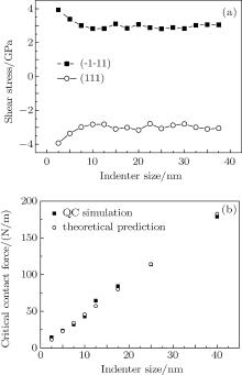
According to Eq. (8), the critical shear stresses on the active slip planes are calculated and plotted with respect to the indenter size as shown in Fig. 6(a). Clearly, the critical shear stress is almost a constant, which is very close to the value 2.84 GPa predicted by density functional theory, except that the one under the 2.5-nm-indenter is a little larger. Although there is difference in incipient dislocation activity between under the 17.5-nm-indenter and under the 2.5-nm-indenter, the reason is not of the stress value, but the deformation intensity. In other words, there are more severely stressed atoms under the 17.5-nm-indenter than under the 2.5-nm-indenter, which is demonstrated by Figs. 5(a) and 5(b). A simple planar fault ribbon generated by merely several partials shown in Figs. 4(a) and 4(b) is not sufficient to release the accumulated stress under the 17.5-nm-indenter. This assumption can be supported by Figs. 2(c) and 2(d), which give the reductions of strain energy 2.79× 10− 10 J/m and 197× 10− 10 J/m respectively. The two energy reductions trigger the defect nucleation events under the two indenters, which are presented by Figs. 4(b) and 4(e). Based on Peierls– Nabarro dislocation model, the core energy of a partial dislocation in a unit length can be estimated to be 0.89× 10− 10 J/m.[50] It is deduced that only three partial dislocations can be generated under the 2.5-nm-indenter, while more than two hundred partials are needed to release the strain energy for the 17.5-nm-indenter. This estimation is qualitatively consistent with the defect structures in Figs. 4(b) and 4(e), though lots of stacking faults and twins instead of partials are nucleated.
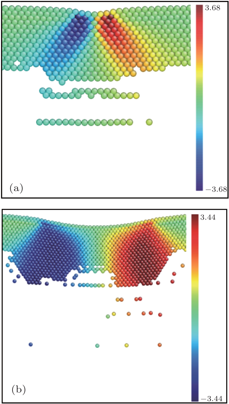 | Fig. 5. Shear stresses at an atomic level under different indenters (R= 2.5 nm (a) and 17.5 nm (b)) immediately prior to the onsets of plasticity. All values are in the units of GPa. |
The critical contact force prior to the onset of plasticity under 2.5-nm-indenter is 14.65 N/m, while the value for 17.5-nm-indenter is 84.29 N/m. Other indenters with various sizes are also tested, and the critical forces are given in Fig. 6(b). The critical force can also be estimated by the elastic theory proposed by Tadmor et al., [32] which is expressed as

where v is the Poisson’ s ratio, G denotes the shear modulus and can be taken to be 27 GPa, according to the equation G = 1/5(C11 − C12 + 3C44).[42] Our results show that the incipient plasticity under a small indenter whose radius is less than ten nanometers is mainly dominated by a simple defect, such as a stacking fault ribbon or a thin deformation twin. As discussed by Ziegenhain and Urbassek, pure planar stacking faults formed under the indenter can heal up as long as no cross-slip occurs, [22] thus the critical forces in the initial stage in Fig. 6(b) correspond to reversible plastic deformation. For the incipient plasticity under the indenter whose radius is larger than fifteen nanometers, a more complex dislocation activity is preferred, and the plastic deformation can be stabilized, since the dislocations will not vanish completely after the indenter has been withdrawn as illustrated by Figs. 4(d)– 4(f). Further study on the intermediate regime in Fig. 6(b) is still needed.
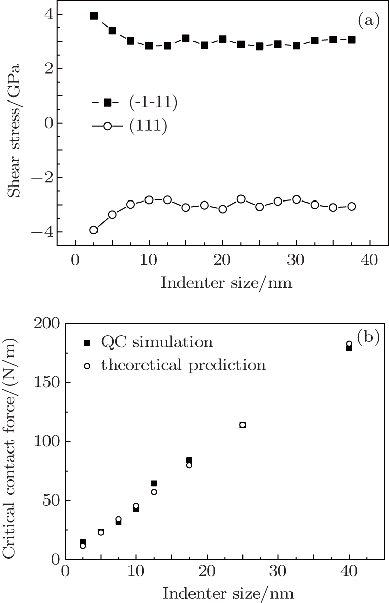 | Fig. 6. Indenter size dependences of critical shear stress (a) and contact force (b). |
The indenter size effect on the reversible incipient plasticity of Al (001) surface is studied by using the QC method. The penetration and withdrawal of cylindrical indenters in various sizes are performed respectively, under displacement-control in steps of 0.02 nm. For example, the incipient plastic deformation processes under the indenters with radii of 2.5 nm and 17.5 nm are presented and analyzed. Some conclusions can be drawn below.
(i) When the incipient plasticity occurs, the contact pressures under the 2.5-nm-indenter still agree with the theoretical elastic calculations quite well, while the contact pressures under the 17.5-nm-indenter deviate from the theoretical predictions seriously.
(ii) After full retraction of indenters, the residual indentation depth under the 2.5-nm-indenter is reduced to zero, while the residual indentation depth under the 17.5-nm-indenter remains unchanged. Thus, the initially plastically deformed surface under the small indenter is recoverable; otherwise the surface is permanently damaged.
(iii) Under the 2.5-nm-indenter, a simple planar fault, which is active only in one slip system, is nucleated at the onset of plasticity, so that the reversibility of plasticity is driven by removing the partial dislocations under the influence of imaging forces from surface and repelling forces from stacking fault energy. Under the 17.5-nm-indenter, multiple slip systems are activated simultaneously when the plasticity occurs, and the debris of defects, such as deformation twins, dislocations, and stacking fault ribbons, still remains beneath the surface after full retraction of the indenter. Accumulated shear stress plays a key role in the distinguishing between the defect structures under the two indenters at the initial stage of plasticity.
(iv) Critical contact forces prior to the initial nucleation of defects under indenters with various sizes are consistent with theoretical estimations. However, it seems that there exists a reversible– irreversible transition of incipient plasticity induced by indenter size, when the radius of indenter is in a range of 10 nm– 15 nm.
In summary, the present simulations are constrained in the quasi-two-dimensional geometry, showing that one should be cautious to compare the above QC results with experimental results. Still, our findings provide some beneficial insights into the incipient surface plasticity of FCC metals induced by nano-sized contacts.
All of the simulations and calculations were performed by using the QC code, which is provided by Tadmor and Miller.
| 1 |
|
| 2 |
|
| 3 |
|
| 4 |
|
| 5 |
|
| 6 |
|
| 7 |
|
| 8 |
|
| 9 |
|
| 10 |
|
| 11 |
|
| 12 |
|
| 13 |
|
| 14 |
|
| 15 |
|
| 16 |
|
| 17 |
|
| 18 |
|
| 19 |
|
| 20 |
|
| 21 |
|
| 22 |
|
| 23 |
|
| 24 |
|
| 25 |
|
| 26 |
|
| 27 |
|
| 28 |
|
| 29 |
|
| 30 |
|
| 31 |
|
| 32 |
|
| 33 |
|
| 34 |
|
| 35 |
|
| 36 |
|
| 37 |
|
| 38 |
|
| 39 |
|
| 40 |
|
| 41 |
|
| 42 |
|
| 43 |
|
| 44 |
|
| 45 |
|
| 46 |
|
| 47 |
|
| 48 |
|
| 49 |
|
| 50 |
|