

Contact angle hysteresis in electrowetting on dielectric
[Zhao Rui† , Liu Qi-Chao, Wang Ping, Liang Zhong-Cheng]
, Liu Qi-Chao, Wang Ping, Liang Zhong-Cheng]
|
|


†Corresponding author. E-mail: zhaor@njupt.edu.cn
*Project supported by the Natural Science Foundation of Jiangsu Province, China (Grant No. BK2011752).
Contact angle hysteresis (CAH) is one of the significant physical phenomena in electrowetting on dielectric (EWOD). In this work, a theoretical model is proposed to characterize electrowetting evolution on substrates with CAH, and the relationship among apparent contact angle, potential, and some other parameters is quantified. And this theory is also validated experimentally. The results indicate that our theory and equation based on energy balance succeed in describing the electrowetting response of potential with significant contact angle hysteresis. The CAH in EWOD, ranging from 0° to about 20° in electrowetting cycle, increases with the increase of voltage and climbs up to about 20° when voltage is increased to about 38 V, and then decreases to zero with the further increase of voltage.
In recent years, electrowetting on dielectric (EWOD)[1– 6] is a well-known approach to reducing the contact angle when an electric field is applied between a droplet and a dielectric coated electrode, [7] which has been widely used to control the wettability of solid surface in electric-controlled liquid lenses, [8– 12] electronic displays, [13– 15] and microfluidic devices.[16– 20] However, it is adversely hindered by contact angle hysteresis (CAH). CAH, as one of the significant physical phenomena in electrowetting, is defined as the difference between the advancing contact angle (voltage increasing) and receding contact angle (voltage decreasing) at the same voltage, which restricts the applicable scope and further progress of EWOD.[6, 21]
Several researchers have devoted their efforts to depict the CAH behavior and to explore the mechanism of CAH in EWOD evolution. Huh and Scriven[22] assumed that the moving process of the contact line was dominated by the viscous dissipation of the liquid and then erected a hydrodynamic model. In contrast to the hydrodynamic model, the molecular kinetic theory (MKT)[23] model built by Blake and Haynes, [24] neglected viscous dissipation and took the solid-surface characteristics into account. Yuan and Zhao[25] developed MKT to explore and simulate the atomic details and the transport properties of the precursor films, describe the contact-line friction caused by adsorption and desorption of liquid molecules on solid in electrowetting. Walker et al.[26] derived a phenomenological model with hysteresis, but the viscous friction was neglected. Rohini Gupta et al.[27] built a new formula, which reformed the Lippmann– Young’ s equation[28] to characterize the electrowetting with significant contact angle hysteresis at low potential. However, their theory ignores the viscous dissipation of the insulating liquid, and only focus on the lower potential. Li and Mugele[29] claimed that the contact angle hysteresis for sessile drops in electrowetting almost disappears with increasing alternating voltage, whereas for direct voltage it remains constant, which was explained in terms of a balance among surface tension, pinning, and electrostatic forces at the contact line. Unfortunately, their work does not mention the dynamic CAH in electrowetting.
In this paper, a theoretical model based on energy balance is established to describe CAH behavior in EWOD evolution. We assume that pinning force, dynamic three-phase contact line (TCL) friction, and viscous dissipations of the insulating liquid have remarkable influences on the CAH. Here the electrowetting cycle is composed of the advancing period and the receding period, where the advancing period corresponds to the stage of increasing voltage, while the receding period refers to the stage of electrowetting evolution at decreasing voltage. The variation of frictions around three phase contact line, induced by applied voltage is analyzed in detail and the relationship between apparent contact angle and voltage is accordingly established. In the meantime, a series of experiments is carried out to verify our theory. The results show that our theoretical prediction of CAH in electrowetting cycle is in reasonable agreement with experimental result, where the CAH in EWOD ranges from 0° to about 20° in electrowetting cycle. It increases with the increase of voltage and climbed up to about 20° when voltage is increased to 35 V, and then starts to decrease to zero with the further increase of voltage. The relevant results may enrich the research of electrowetting and expand the application scope in electrowetting devices.
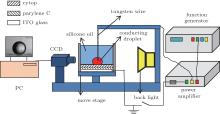
The basic electrowetting testing setup is shown in Fig. 1. Test substrates consisted of aluminosilicate glass coated with a transparent indium tin oxide (ITO). The ITO was coated with parylene C with a thickness of 1.0 μ m. Cytop was spin-coated onto the parylene C as a hydrophobic fluoropolymer layer of about 50 nm in thickness. The electrowetting substrates were placed in a clear box and immersed in oil. The tested insulating oil was silicone oil (surface tension γ = 20 mN/m). The conductive fluid was NaCl (2 wt%, surface tension γ = 75 mN/m), which was deposited with a pipette (drop 0.5 μ l) and electrically biased through the insertion of a tungsten probe tip (10 μ m in diameter) connected to a Trek Power Amplifier coupled to a Tektronix AFG 3022B function generator. Voltages were applied at a step rate of 1 V/s with the ITO held at electrical ground. The data were measured and recorded by Dataphysics OCA20. All data sets were repeated at least 3 times at a fresh sample location and data were plotted as an average curve.
 | Fig. 1. Sketch of the contact angle measurement setup (Dataphysics OCA20). |
As is well known, the apparent contact angle decreases with increasing voltage while increases with reducing voltage in electrowetting cycle. When voltage is increased from 0 V to Vm, where Vm is the maximum voltage in experiment, the electrowetting cycle corresponds to the advancing period, while the receding period is defined as the process of electrowetting evolution when voltage is modulated from Vm to 0 V.
In advancing period, the evolution of electrowetting is split into three processes. When the applied voltage is modulated from 0 V to V1, the TCL is pinned because of static friction and hence the apparent contact angle remains unchanged. Here the relevant process is defined as the first stage of the advancing period and V1 denotes the threshold potential corresponding to the critical state of TCL advancing or pinned. When the applied voltage exceeds V1, the electrostatic field force overcomes the maximal pinning force and then drives the TCL advancing, which triggers the second stage of the advancing period. Compared with viscous dissipation, the dynamic contact line friction has a strong influence on electrowetting evolution and the correlated CAH in this stage. When the applied voltage reaches a certain value V2, the velocity of TCL tends to decrease. It is due to the saturation phenomenon. The electrowetting evolves into the third stage of the advancing period accordingly when the applied voltage ranges from V2 to Vm. The applied voltage begins to decrease instead of increase subsequently, and the corresponding electrowetting enters into the receding period.
In the receding period, the evolution of electrowetting is divided into two stages. The first stage denotes that the apparent contact angle remains value θ m when voltage varies from Vm to V3, where θ m refers to the contact angle of the droplet corresponding to the potential Vm, V3 is defined as the threshold potential of the receding period, i.e., the TCL starts to recede once the voltage drops below V3. When the voltage is modulated from V3 to zero, TCL starts to recede and hence the apparent contact angle begins to decrease. Compared with the scenario in the advancing period, the contact line friction force and viscous force change their directions, and the electrowetting enters into the second stage of the receding period.
Deliberate a situation of a droplet spreading on an insulating layer as the effect of an applied electric potential. In the electrowetting process, the conducting droplet is assumed to keep spherical to simplify the problem. For a conducting droplet with the spherical shape illustrated in Fig. 2, the volume (V0), conducting droplet/insulating layer interfacial area (A12), and insulating fluid/conducting droplet interfacial area (A13) can be represented, respectively, as


where R is the liquid droplet radius, θ is the apparent contact angle, γ 23, γ 13, and γ 12 are the surface tensions at the insulating fluid/insulating layer, conducting droplet/insulating layer, and insulating fluid/conducting droplet interfaces.
 | Fig. 2. Schematic diagram of a droplet characterized by radius R and contact angle θ . |
The derivative of the volume (V0) with respect to R and θ is given by

Substituting Eq. (1) into Eq. (4), then the resulting equation becomes
Assume that the energy is a function of R and θ , then in the equilibrium the derivative of the total interfacial potential energy (Etot) equals zero, i.e.,

In order to show how the energy changes with contact angle, equation (6) is rewritten as

In the first stage of the advancing period, the insulating fluid/conducting droplet surface tension energy (E1), base tension energy (E2), dielectric energy (E3) can be expressed, respectively, as


where fcl, sta is the static friction at the contact line under electric potential V, ε r and ε 0 are the relative permittivity of the dielectric layer and the dielectric constant in a vacuum, d is the thickness of the dielectric layer.
The total interfacial potential energy (Etot) of a droplet is determined by combining E1, E2, and E3, and is represented as[30]
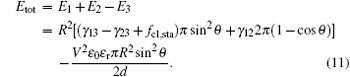
Substituting Eqs. (5) and (11) into Eq. (7), the relationship between apparent contact angle and voltage with CAH considered is written as

In this work, the initial contact angle of the sessile drop is defined as the contact angle θ 0, which is the equilibrium contact angle without voltage and follows Young’ s equation. When voltage is applied, the static friction fmcl, sta offsets the increasing electrostatic force around the contact line before the contact line moves, i.e., fcl, sta = ε 0ε rV2/2d. In consequence, before the contact line moves, equation (12) changes into Young’ s equation

Based on the molecular kinetic theory, [23] the dynamic part of the friction force per unit length on the TCL in the second stage of the advancing period, is a function of the velocity:[31]

where ζ is the coefficient of contact line friction and U is the velocity of TCL.
According to Stokes’ law, [32] the velocity of a small ball with a radius, a, in a liquid is[33]
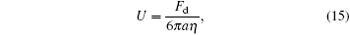
where Fd and η are the force exerted on the small ball and kinematic viscosity of the liquid, respectively.
Assume that the total force is exerted on a semicircular length L = aπ , then the equivalent viscous force on the per unit length of TCL coming from the silicone oil will be derived as

Based on the balance between driving work and energy dissipation, the relationship between contact line velocity U and applied voltage V can be written as[34]

where k1 is a constant, and C = ε 0ε r/d is the effective capacitance per unit. The base tension energy E2 in this stage becomes

where cpin is the maximum pinning force per unit length of TCL, which is a part of the friction force and can be determined by the initial condition of this experiment.[26, 35]
Then the total interfacial potential energy Etot is represented as
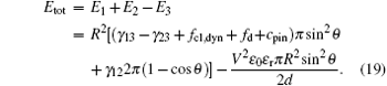
Substituting Eqs. (14), (16), and (17) into Eq. (19), and then substituting the resulting equation into Eq. (7), we can obtain the following equation:
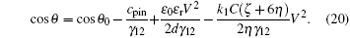
In the third stage of the advancing period, electrowetting evolves closer to the electrowetting saturation. Here, the relationship between contact angle and voltage can be describe as[36]
where G is the Langevin’ s function, and θ S is the saturation angle. Rearrange of Eq. (21) leads to

Till now, the combination of Eqs. (13), (20), and (22) describes the contact angle variation with applied voltage increasing from zero to Vm.
Then the voltage decreases from Vm to zero, and the TCL experiences two different processes, i.e., the triple contact line remains pinned and the TCL starts to recede. That is to say, in the first stage of receding period, the TCL is pinned and the apparent contact angle θ = θ m.
When the applied voltage drops below V3, base tension energy E2 becomes

With the viscous dissipation and contact line friction of TCL considered, the variation of the apparent contact angle with applied voltage can be written as
In summary, the relationship among apparent contact angles, initial angle, potential, and viscosity in an electrowetting cycle can be expressed as
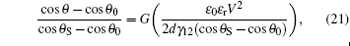
Figure 3 shows the experimental data (dots) and the theoretical results (dashed line) predicted by Eq. (25). In this work, the physical and electrical property parameters in Eq. (25) have values: initial contact angle θ 0 = 162.4° , the dielectric constant of the insulating layer ε r = 3, the thickness of the dielectric layer d = 1 μ m, the surface tension γ 12 = 17 mN/m, the kinematic viscosity of the silicone oils η = 1.92 × 10− 3 Pa· s, the coefficient of contact line friction ζ = 0.08 dynes· s/cm2 (1 dyn = 10− 5 N), the maximum voltage Vm = 50 V, and the saturation angle θ S = 57° .
 | Fig. 3. Comparison between theoretical and experimental dependence of the contact angle on the applied voltage. |
In Fig. 3, the CAH ranges from 0° to 20° , increases with voltage when voltage is modulated from 0 V to V3 and reaches the maximum value 20° at about 38 V predicted by the theoretical model while 18° at about 35 V detected from the experiments, and then it starts to decrease reversely when voltage is modulated from V3 to Vm. Comparing the experimental data with the theoretical curve, it is evident that our theoretical model shows a satisfactory agreement with the experimental data and achieves a reasonable prediction of the relationship among static friction, contact line friction, viscous force, and energy dissipation in different stages of advancing and receding period. The results validate the prediction that in the advancing period the static friction is dominant initially, then followed by the dynamic friction and viscous dissipation, while in the receding period, static friction and then dynamic friction occupy the central place successively.
The research in this paper focuses on the depiction of contact angle hysteresis in electrowetting cycle. The influences of various frictions including static friction, dynamic friction, and viscous friction around three phase contact lines on the CAH are analyzed, and then a theoretical model and relationship between apparent contact angle and voltage based on energy balance are accordingly established. A series of experiments is also carried out to verify these theories. The CAH in EWOD ranges from 0° to about 20° in electrowetting cycle, increases with the voltage and climbed up to about 20° when voltage is modulated around 38 V, and then starts to decrease to zero with the increase of the applied voltage. These results show that our theoretical prediction of CAH in electrowetting cycle is in good agreement with the relevant experimental results. These findings will enrich the research of electrowetting, promote the application and then expand its application scope.
| 1 |
|
| 2 |
|
| 3 |
|
| 4 |
|
| 5 |
|
| 6 |
|
| 7 |
|
| 8 |
|
| 9 |
|
| 10 |
|
| 11 |
|
| 12 |
|
| 13 |
|
| 14 |
|
| 15 |
|
| 16 |
|
| 17 |
|
| 18 |
|
| 19 |
|
| 20 |
|
| 21 |
|
| 22 |
|
| 23 |
|
| 24 |
|
| 25 |
|
| 26 |
|
| 27 |
|
| 28 |
|
| 29 |
|
| 30 |
|
| 31 |
|
| 32 |
|
| 33 |
|
| 34 |
|
| 35 |
|
| 36 |
|