

Particle-in-cell simulation for different magnetic mirror effects on the plasma distribution in a cusped field thruster
[Liu Hui, Chen Peng-Bo† , Zhao Yin-Jian, Yu Da-Ren]
, Zhao Yin-Jian, Yu Da-Ren]
|
|


†Corresponding author. E-mail: 1151786040@qq.com
*Project supported by the National Natural Science Foundation of China (Grant No. 51006028) and the Foundation for Innovative Research Groups of the National Natural Science Foundation of China (Grant No. 51121004).
Magnetic mirror used as an efficient tool to confine plasma has been widely adopted in many different areas especially in recent cusped field thrusters. In order to check the influence of magnetic mirror effect on the plasma distribution in a cusped field thruster, three different radii of the discharge channel (6 mm, 4 mm, and 2 mm) in a cusped field thruster are investigated by using Particle-in-Cell Plus Monte Carlo (PIC-MCC) simulated method, under the condition of a fixed axial length of the discharge channel and the same operating parameters. It is found that magnetic cusps inside the small radius discharge channel cannot confine electrons very well. Thus, the electric field is hard to establish. With the reduction of the discharge channel’s diameter, more electrons will escape from cusps to the centerline area near the anode due to a lower magnetic mirror ratio. Meanwhile, the leak width of the cusped magnetic field will increase at the cusp. By increasing the magnetic field strength in a small radius model of a cusped field thruster, the negative effect caused by the weak magnetic mirror effect can be partially compensated. Therefore, according to engineering design, the increase of magnetic field strength can contribute to obtaining a good performance, when the radial distance between the magnets and the inner surface of the discharge channel is relatively big.
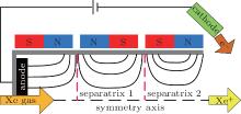
The cusped field thruster represents a new type of electric propulsion device. A schematic view of the concept of cusped field thrusters with its unique magnetic field topology is shown in Fig. 1. The specific magnetic field topology in cusped field thrusters is formed by a quasi-periodic permanent magnet configuration, which can confine plasma and minimize plasma– wall interaction efficiently. Meanwhile, compared with traditional Hall thruster, the cusped field thruster has a long lifetime which is one of its most significant merits. One type of cusped field thruster, named the high efficiency multistage plasma thruster (HEMPT), has been demonstrated to have a more than 8000-h lifetime and it is going to be launched soon.[1] One experimental measurement indicates that the maximum erosion rate of a diverging cusped field thruster (DCFT) designed by MIT is found to be lower than the rates measured in low-power Hall thrusters, and the lifetime of this laboratory prototype is estimated at 920 h– 1220 h based on the time needed to erode through the insulator in one of the ring-cusps.[2] On the other hand, it has been confirmed experimentally that the cusped field thruster has a wide range of operational parameters[3] with good performance. Consequently, the cusped field thruster has received much attention recently by many organizations, such as the Thales Research Institute’ s HEMPT, [4] MIT’ s DCFT, [5] and Stanford University’ s CCFT.[6]
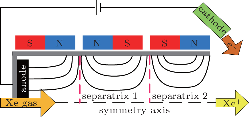 | Fig. 1. Schematic view of the concept of cusped field thrusters. |
Magnetic mirror used as an efficient tool to confine plasma has been widely used in many different areas.[7] In a traditional Hall thruster, the magnetic mirror effect has been studied by Keidar and Boyd.[8] Their result shows that the length of the radial presheaf region decreases in the presence of a magnetic field gradient, and it is possible to obtain a concave shape of the potential profile in the channel even in the case of a primarily radial magnetic field, which can be used to efficiently control the ion dynamics in the acceleration region. Compared with Hall thrusters that the mainly impedance for electrons results from the radial magnetic field, a cusped field thruster has the magnetic mirrors at cusps, which play the most important role to confine electrons. A simple physical process in a cusped field thruster is as follows. Electrons emitted from the cathode will firstly be confined at the cusp near the channel exit, because of both the cross-field impedance for electrons near the separatrix shown in Fig. 1 (magnetic separatrix separates the B-lines at the axis bending upstream of symmetry from those bending downstream[9]) and the strong magnetic mirror effect at the cusp. By the collision with atoms or the wall, electrons can pass through the separatrix and cusp to enter into the discharge channel. Inside the channel, the physical process is repeatable until electrons arrive at the anode and disappear. In short, the axially distributed magnetic field contributes to keeping the plasma from bombarding the insulated wall in order to extend the thruster’ s lifetime. And the axial movement of electrons is restricted by the cross-field impedance at each radial magnetic separatrix combined with the magnetic mirror effect at cusps. Some researches have been done concerning the magnetic mirror effect in a cusped field thruster. Sanchez and Ahedo presented a kinetic model of the plasma in the vicinity of one cusp and found that the cusp does not reduce the ion flux (per unit area) to the wall and only reduces the size of the wall area section that carries this flux by its connection to the distant plasma.[10] All in all, magnetic mirror effect plays a dominant role in a cusped field thruster and it is necessary to undertake more research to learn the deeper physics mechanism in it.
As is well known, the magnetic mirror effect inevitably leads to the loss of plasma particles. In a cusped field thruster, the leak width at cusp, which is a measure of the footprint of the collection for the plasma at cusp, [11] can reflect the extent and the performance of the magnetic mirror effect. With respect to theoretical studies, the leak width at cusp is not fully understood now. At very low pressures, theoretical calculations are confirmed by measurements from Hershkowitz.[12] However, the leak width is observed to increase with pressure and is much larger than Hershkowitz et al.’ s calculations.[13] The mechanism for this increase in leak width is that ions and electrons collisionally diffuse across magnetic field lines, and diffuse or flow along the field lines to the wall. Hubble et al.[11] have also done some similar research, and the result shows that the leak width scale with hybrid gyroradius and the scaling constant of proportionality increase with pressure increasing. The above theoretical calculations are simply based on a closed system without strong electric field, but in cusped field thrusters the leak width at cusp will be inevitably more complicated. Therefore, some numerical simulations like Particle-in-Cell plus Monte Carlo simulation should receive more attention to offset shortcomings of present theories.
Numerical simulation is regarded as a convenient tool to reveal the influence of the magnetic field on the plasma distribution in a cusped field thruster. Since the complicated magnetic field topology and the strong electric field will make electrons deviate from Maxwellian distribution, the Particle-in-Cell plus Monte Carlo (PIC-MCC) method is more suitable to the study of the physical mechanism in a cusped field thruster. Some work concerning the PIC-MCC simulation of cusped field thrusters has already been done. Schneider’ s PIC-MCC simulated results[14] demonstrated that the HEMPT type cusped field thruster possesses a good performance due to both minimal energy dissipation and high acceleration efficiency. The interaction between the plasma and the wall is limited to the cusps, which results in much smaller ion flux to the thruster channel surface than in Hall thruster. In addition, Gildea[15] and Gildea et al.[16] have simulated divergent cusped-field thrusters (DCFTs) by using the PIC-MCC method and revealed some physical processes of the plasma under the specific cusped magnetic field topology.[15, 16]
In this paper, by reducing the radius of the discharge channel with a fixed magnetic field configuration, the magnetic field strength at cusp will definitely be reduced. Electrons that can be reflected at cusps before have a bigger possibility to bombard the wall surface now due to the lower magnetic mirror ratio here. Therefore, the extent and the effect of magnetic mirrors can be estimated easily by changing the radius of the discharge channel. In addition, with regard to engineering design, the researches on different discharge channel diameters with fixed magnetic configuration can contribute to figure out the influence of the radial space between magnets and the channel, since big space can prevent magnets from overheating, but it will inevitably influence the magnetic configuration inside the discharge channel negatively, especially at cusps. Therefore, the research about investigating different radii of the discharge channels with fixed magnetic configuration can also contribute to the engineering design of a cusped field thruster in the future. The rest of this paper is organized as follows. In Section 2, the simulation model of a cusped field thruster is introduced. In Section 3, simulation results of several models with different radii are presented and analyzed. In Section 4, a stronger magnetic field is investigated to compensate for the weak magnetic mirror effect in the model with small radius of the discharge channel. Finally, some conclusions are drawn and future prospects are described.
Simplified rotative cusped field thruster models without a plume zone are established. The computational rectangular domain together with magnetic field topology is shown in Fig. 2. In our simulations, the magnetic field configuration and the length of the computational rectangular domain (Z = 57 mm) are fixed. In order to investigate the influence of magnetic mirror, we change the radius of the model. According to these dashed lines shown in Fig. 2, we change R into 6 mm, 4 mm, and 2 mm, corresponding to R6 model, R4 model, and R2 model respectively. The magnetic field is generated externally and preprocessed by FEMM[17] software.
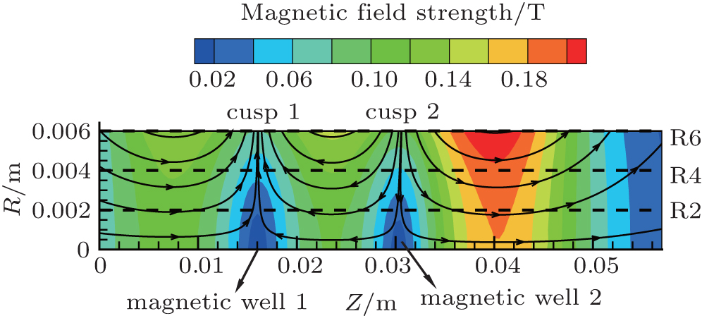 | Fig. 2. Computational rectangular domain together with magnetic field topology. |
In all the models, two-dimensional (2D) space (radial and axial) and three-dimensional (3D) velocity components (2d-3v) are taken into account. The lengths of cusped magnetic field region from anode to exit are 16 mm, 15 mm, and 26 mm respectively, which are the characteristic sizes of HIT’ s experimental cusped field thrusters. The two lateral boundaries shown in Fig. 2 are the anode (left) and the cathode (right) respectively. The lower and upper boundaries are the symmetric axis and a boron nitride dielectric wall. The Boris’ s leapfrog method is used to resolve Newton’ s equations.[18] The elastic scattering, excitation and single ionization between electron and neutral are modeled by an MCC technique, [19] with appropriate scattering cross sections.[20] Due to the small collision frequency, the ion– neutral collisions, Coulomb collisions and three-body radiative recombinations are neglected. Secondary electron emission (SEE) is considered at the dielectric walls. The SEE and electric field models at dielectric walls by Morozov are used.[21] The electric field at the dielectric surface is E⊥ = σ /ε 0, here E⊥ is the electric field perpendicular to the wall, and σ is the surface charge density collected by the wall. The ε 0 is the free space permittivity. More details about the simulated method used in this paper are similar to one of our recent work.[22]
The PIC-MCC method has been widely used for the simulation of Hall thrusters. Due to the similar physical process inside the discharge channel, it can also be used to simulate the discharge process in a cusp field thruster. In general, the PIC method employs the fundamental equations without much approximation so as to retain the major physics processes. But the primary disadvantage of the PIC method is the computational cost due to the large number of particles, the grid spacing, and the time step required for the basic plasma characteristics. In order to speed up convergence, two different methods are put forward by Szabo[20] (by increasing the artificial permittivity and by reducing the heavy particle mass) and Taccogna et al.[23] (by reducing the size of the domain and by increasing the strength of the magnetic field). In our recent work, we found that both of the former methods for acceleration, which adopt an artificial electron-to-ion mass ratio and a geometrical scaling of the channel, change the interaction of plasma with magnetic field and walls.[24] This makes it difficult to rescale the numerical results to the original system. In order to solve these problems, only the vacuum permittivity constant is increased by a factor of γ 2 = 1600 to reduce the number of grids and iterations in this paper. After that, the maximum Debye size is about 0.5 mm, which is still far smaller than the characteristic size of the discharge channel. What is more, the plasma oscillation frequency ω pe can be much reduced by this method, which allows a bigger time step Δ t to be used. However, it should be noticed that the greater artificial permittivity can also lead to larger sheath and more serious charge unbalance. By testing the simulation code with different values of γ 2, it is found that the charge unbalance degree changes little when γ 2 < 1600. So we set γ 2 to be 1600. The feasibility of this method has already been proved in our recent simulation work.[22]
In order to further reduce the calculated quantity and make the simulation convergent, the atom density is given by solving the fluid flow equations. By ignoring the time term of the partial derivative, neither the variation of neutral density with time nor the corresponding low frequency oscillation can be depicted. However, this method of acceleration can model the influence of the magnetic field and wall effect on plasma behavior more accurately. The cathode boundary is at the ground potential, and a quasi-neutrality cathode model is used to inject electrons into the computational domain at a temperature Te = 5 eV. The voltage U = 300 V is applied to the anode, and the atom flux is 1 mg/s. The values of time step Δ t are smaller values (0.1/ω pe and 0.35/ω c), where ω c is the electron cyclotron frequency. The cell size Δ R = Δ Z = 0.5 mm in the simulation is chosen to ensure that it is smaller than the smallest Debye length in the system. The simulation is performed by using a personal computer with the above simplified model. After about a three-day calculation, convergent results are obtained successfully.
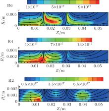
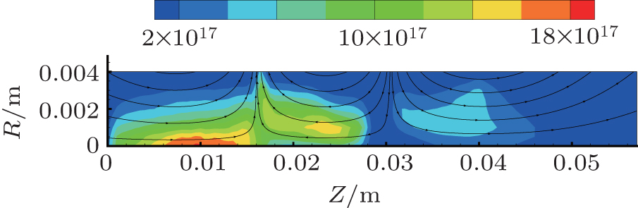
The simulation results of electron density distribution with different radii are shown in Fig. 3. Comparing R6 model with R4 model, with the reduction of the radius, due to lower magnetic mirror ratio, the effect of magnetic mirror at cusp is weakened, and electrons cannot be well confined at cusps anymore. In consequence, more electrons leave cusp 1 and cusp 2 and enter into the region with higher atom density, then realize the ionization of neutral atoms, thus resulting in the highest electron density occurring in the centerline area between cusp 1 and the anode, where there are enough atoms to be ionized as shown in the R4 model. For the same reason, in R2 model the highest electron density will occur in these regions near the anode where more electrons can be generated by ionization due to the highest atom density.
In addition, the simulated results indicate that the maximum value of electron density shown in R4 model is slightly higher than in R6 model. It is because under the fixed atom flux at the anode, the decrease of the radius will lead to larger atom density per unit cross section. Hence, the overall ionization ratio could increase, which will generate more electrons. However in R2 model, because the weak magnetic mirror effect cannot confine enough electrons anymore, the maximum electron density is not so high.
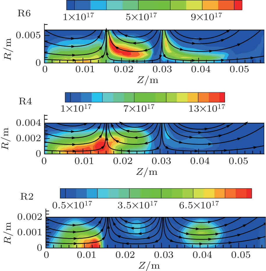 | Fig. 3. Electron density distributions with different radii. |
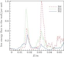
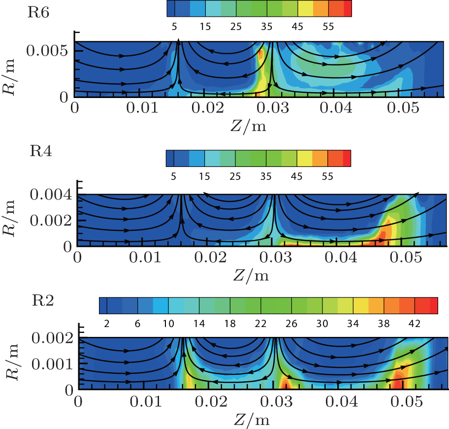
The distribution of the ion energy flux to the wall is presented in Fig. 4. At the beginning, R6 model indicates a much higher ion energy flux to the wall at cusp 2 than at cusp 1 (Cusp 1 and cusp 2 are marked in Fig. 2). When the radius decreases to that in R4 model, the ion energy flux to the wall at cusp 1 becomes higher than at cusp 2, which indicates that cusp 2 plays a lesser role in confining electrons and ionizing atoms, and the accompanying main ionization regions ought to move inside the discharge channel toward the anode. When it comes to R2 model, both cusp 1 and cusp 2 present a much lower ion energy flux to the wall, but the leak width at cusp 1 will increase in the meantime. On the other hand, contrary to intuition, compared with the weak magnetic mirror effect in R2 model, the strong magnetic mirror effect in R6 model presents a high ion energy flux to the wall instead of low ion energy flux, which is consistent with the result obtained from Sanchez and Ahedo’ s kinetic model.[10] It indicates that the cusp does not reduce the ion flux (per unit area) to the wall and only the size of the wall area section that carries this flux through its connection to the distant plasma.
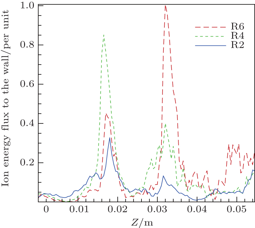 | Fig. 4. Ion energy fluxes to the wall (per unit area) for three different models. |
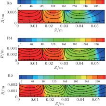
From the distribution of potential shown in Fig. 5, we can figure out that with the decrease of the radius, the potential drop at the cusp becomes much less due to the decrease of electron impedance for electrons, resulting from the magnetic mirror effect becoming weaker. Between cusps, where the magnetic lines are most parallel to the axis, electrons can move freely, thus forming an almost constant potential. And with the decrease of the radius, the radial potential distribution becomes more constant and homogeneous.
 | Fig. 5. Potential distributions with different radii. |
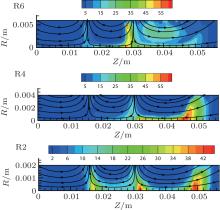
The electron temperature distributions are presented in Fig. 6. R6 model shows that the highest electron temperature occurs after cusp 2, because there is a main potential drop to convert the electric-field energy into kinetic energy of electrons. After reducing the radius of the discharge channel, the cusp 2 cannot generate enough potential drop to increase the electron temperature. However, in R4 model the highest electron temperature is near the exit, because of the obvious potential drop here as shown in Fig. 5. For R2 model, due to the weak magnetic effect, each cusp will generate a potential drop as shown in Fig. 5, which results in the electron temperature peak occurring in each cusp.
 | Fig. 6. Electron temperature distribution with different radii. |
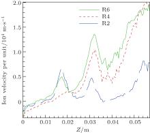
The ion axial velocity distributions at the centerline of the discharge channel for three different models are shown in Fig. 7. In R6 model, the accelerations of ions are obvious at the two cusps, and the increase of the axial velocity at cusp 2 is much higher than at cusp 1, because of the bigger potential drop at cusp 2. With the decrease of the radius, the contribution of cusp 2 to accelerating ions becomes less, because the cusp 2 cannot impede electrons’ generating the potential drop. For R4 model, we can see that the ion velocity at cusp 1 is much smaller than at cusp 2. And as a result of the weak electric field established at two cusps in model R2, the whole ion axial velocity has become much less, and the cusp 1 has more contribution to the acceleration of ions than the cusp 2 because the dominant potential drop lies in the cusp 1. Consequently, the decrease of the radius of the discharge channel, namely the weak of the magnetic mirror effect at cusp is negative for ion acceleration.
 | Fig. 7. Ion axial velocity distributions at the centerline for three different models. |
Because the reduction of the discharge channel’ s radius will inevitably weaken the magnetic mirror effect at cusp, we consider multiplying the whole magnetic field strength to compensate for the negative effect caused by the weak magnetic mirrors at cusps. And with regard to engineering, the stronger magnetic field strength can be easily achieved by increasing the radial thickness values of the magnet rings.
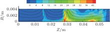
After increasing the magnetic field strength in R4 model (the maximum magnetic field strength is increased from 0.2 T to approximately 0.38 T), the confinement of electrons in the discharge channel becomes stronger. The electron density profile is presented in Fig. 8. After increasing the magnetic field strength, more electrons can be confined at cusps, especially at cusp 1 than the case shown in Fig. 3.
 | Fig. 8. Electron density distribution of R4 model in a stronger magnetic field. |
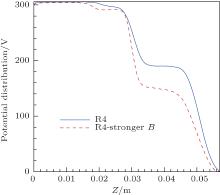
Figure 9 shows the potential distributions at the centerline of two R4 models with different magnetic field strengths. It can be found that the bigger magnetic field strength will give rise to a bigger potential drop at the second separatrix (Z ≈ 0.03 mm), which is considered to be due to stronger impedance for electrons to flow at separatrices and thus increasing the effect of the magnetic mirror at cusps.
 | Fig. 9. Potential distributions at the centerline for two R4 models. |
The electron temperature distribution of R4 model in a stronger magnetic field is shown in Fig. 10, which indicates a higher electron temperature after the second separatrix than that shown in the previous R4 model. It is mainly because the potential drop near the second separatrix is bigger, which converts more electric field energy into electrons’ kinetic energy.
 | Fig. 10. Electron temperature distribution of R4 model in a stronger magnetic field. |
In consequence, the increase of magnetic field strength could compensate for the negative effect resulting from the decrease of the discharge channel’ s radius. Especially, when the radial space between the magnets and the inner surface of the discharge channel is relatively big, we can consider increasing the thickness of the magnet ring to strengthen the magnetic field strength inside the discharge channel.
In this paper, the PIC-MCC method is used to investigate the influence of the magnetic mirror effect on the plasma distribution in a cusped field thruster by changing the radius of the discharge channel. The main results can be concluded as follows.
With the decrease of the discharge channel’ s radius, it becomes harder for the magnetic field with weak magnetic mirror effect to confine the electron flow toward the anode, and more electrons close to the wall could escape to the region with higher atom density, thus more electrons concentrate in the centerline near the anode. Ultimately, the established electric field becomes weak, and it is negative effect on accelerating ions. The result of the ion energy flux to the wall shows that the leak width of the cusped magnetic field will increase with the reduction of the discharge channel’ s radius, which will lead to a decrease of the total efficiency. By multiplying the magnetic field strength in a cusped field thruster with small radius of the discharge channel, the negative effect caused by the weak magnetic mirror effect can be compensated for in some level. Therefore, when the radial distance between the magnets and the inner surface of the discharge channel is relatively big, we can consider increasing the radial thickness values of magnet rings to strengthen the magnetic field strength inside the discharge channel to obtain a good performance of the thruster.
Future simulation work will mainly focus on the addition of the plume zone into the code. And some other methods of accelerating the convergence will be investigated and used.
| 1 |
|
| 2 |
|
| 3 |
|
| 4 |
|
| 5 |
|
| 6 |
|
| 7 |
|
| 8 |
|
| 9 |
|
| 10 |
|
| 11 |
|
| 12 |
|
| 13 |
|
| 14 |
|
| 15 | [Cited within:2] |
| 16 |
|
| 17 |
|
| 18 |
|
| 19 |
|
| 20 | [Cited within:2] |
| 21 |
|
| 22 |
|
| 23 |
|
| 24 |
|