Effects of core position of locally resonant scatterers on low-frequency acoustic absorption in viscoelastic panel
[Zhong Jie, Wen Ji-Hong† , Zhao Hong-Gang, Yin Jian-Fei, Yang Hai-Bin]
, Zhao Hong-Gang, Yin Jian-Fei, Yang Hai-Bin]
|
|


†Corresponding author. E-mail: wenjihong@vip.sina.com
*Project supported by the National Natural Science Foundation of China (Grant No. 51275519).
Locally resonant sonic materials, due to their ability to control the propagation of low-frequency elastic waves, have become a promising option for underwater sound absorption materials. In this paper, the finite element method is used to investigate the absorption characteristics of a viscoelastic panel periodically embedded with a type of infinite-long non-coaxially cylindrical locally resonant scatterers (LRSs). The effect of the core position in the coating layer of the LRS on the low-frequency (500 Hz–3000 Hz) sound absorption property is investigated. With increasing the longitudinal core eccentricity e, there occur few changes in the absorptance at the frequencies below 1500 Hz, however, the absorptance above 1500 Hz becomes gradually better and the valid absorption (with absorptance above 0.8) frequency band (VAFB) of the viscoelastic panel becomes accordingly broader. The absorption mechanism is revealed by using the displacement field maps of the viscoelastic panel and the steel slab. The results show two typical resonance modes. One is the overall resonance mode (ORM) caused by steel backing, and the other is the core resonance mode (CRM) caused by LRS. The absorptance of the viscoelastic panel by ORM is induced mainly by the vibration of the steel slab and affected little by core position. On the contrary, with increasing the core eccentricity, the CRM shifts toward high frequency band and decouples with the ORM, leading to two separate absorption peaks and the broadened VAFB of the panel.
Over the past few years, a typical class of phononic crystal known as locally resonant sonic material[1] (LRSM) has attracted much attention due to its excellent ability to control the propagation of low-frequency elastic/acoustic waves. The low-frequency band gap induced by the resonance of the locally resonant scatterer (LRS) which is normally composed of a heavy core concentrically coated with soft silicone rubber, can lead to a variety of potential applications in vibration isolation and sound insulation.[1– 3]
In recent years, by considering the component viscosity of the material, the acoustic absorption of the LRSM has been analyzed. The low-frequency underwater sound absorption phenomenon induced by localized resonance has been demonstrated both theoretically and experimentally.[4– 7] Furthermore, much effort has been made to analyze absorption mechanism[8– 14] and design wide absorption band[14– 17] or thinner absorption materials.[18]
However, most of the current studies focus on the symmetrical resonators, such as the concentrically spherical or coaxially cylindrical LRSs. The characteristics for asymmetrical resonators, such as the non-concentric or non-coaxial LRSs, have been less reported. More recently, based on the asymmetrical resonators, several new physical features have been analyzed.
Gu et al.[19] analyzed the low-frequency elastic wave propagation in a two-dimensional (2D) locally resonant phononic crystal which is formed by periodic arrangements of a two-block unit cell in one direction, and the unit cell consists of two asymmetric elliptic cylinders coated with silicone rubber. The relationship between the resonance modes and the corresponding transmission troughs or peaks has been discussed. It has been shown that the frequency of the transmission peak is related to the opposite vibrations of the two cylinders in the unit cell, and can be tuned by simultaneously rotating the orientation angle of conjugate elliptical resonators.
Hou et al.[20] investigated the defect state of a 2D solid local resonant phononic crystal on a sub-wavelength scale. The results show that the long-range interaction between resonators can be broken by introducing an eccentric defect resonator. In this way, a waveguide structure that can guide the longitudinal or transverse waves separately can be realized.
In the area of underwater sound absorption materials, asymmetrical resonators also attracted some research attention. Wen et al.[9] analyzed the sound absorption properties of viscoelastic materials containing LRSs in ellipsoidal shape, the results showed that one can tailor the absorption characteristics by changing the shape and/or the orientation of the scatterer. Jiang et al.[21] proposed the locally resonant phononic woodpile structure and verified its broadband absorption performance both theoretically and experimentally. Shang[22] analyzed the absorption characteristic of viscoelastic panel embedded with eccentric spherical LRSs, and found that the front move of the heavy core could improve the absorption performance at medium and high frequencies (above 5 kHz), but has little effect on the absorption at low frequencies.
Inspired by the research work mentioned above, in this paper we focus on the absorption characteristics of a viscoelastic panel containing infinite-long non-coaxially cylindrical LRSs. The finite element method (FEM), which has a good suitability for irregular structures, is used to investigate the influence of the eccentricity of the core on the low-frequency (500 Hz– 3000 Hz) sound absorption. Then, the possible effect mechanism of the core position on sound absorptance is investigated by the displacement field map.
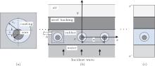
Figure 1(a) shows the cross section of one LRS unit, i.e., the heavy core (with radius rc) non-coaxially coated by soft rubber (with outer radius rs). The longitudinal eccentricity between the heavy core and soft rubber is e. The infinite long cylindrical LRSs are arranged in the rubber matrix along the x direction with the single period a, and the axis of the cylinder is parallel to the z direction as shown in Fig. 1(b). The thickness of the material is h, a plane longitudinal incident wave is from the semi-infinite water and perpendicular to the xoz plane. The viscoelastic panel is bonded to a steel slab followed by semi-infinite air. The whole structure can be regarded as a sequence of different layers perpendicular to the y direction.
 | Fig. 1. (a) Cross section of one LRS unit, i.e., a heavy core with radius rc and an eccentrically coated rubber layer with outer radius rs and a longitudinal eccentricity e. (b) Schematic diagram of the absorption structure and steel backing. (c) Schematic description of one Bloch unit cell. |
Because of the invariance in the z direction, the original three-dimensional (3D) structure can be simplified into a 2D model as shown in Fig. 1(b). According to the Bloch condition, the displacement u in solid and the sound pressure p in water can be incorporated into the following form:

where a is the period (or lattice constant) along the x axis and the wave vector in the x direction is kx = 0. Therefore, we can simplify the absorption problem of the infinite panel into the analysis of one Bloch unit cell as shown in Fig. 1(c). The unit cell is divided into four parts, in which, the first part is semi-infinite water domain, the second part is of viscoelastic material, and the other two parts are steel backing and semi-infinite air domain, the two semi-infinite domains are limited by the surface s− and s+ . Omitting the time dependence e− jω t, the external incident wave can be written as

where the wave number k = ω /c, with c being the sound speed in water, ω the angular frequency, and p0 is the magnitude of incident wave.
In the domain below the s− surface, the total wave field, including both the incident wave and the reflected wave, can be written in a general form:

where 
Analogously, in the domain above the s+ surface, the transmitted wave can be written in a general form:

where

with k′ being the wave number in air.
The finite element description equations for the fluid-structure interaction of a single cell are written as an incorporated matrix form[9, 23]

where ρ 0 is the fluid density, ω denotes the angular frequency, [K] and [M] are, respectively, the structure stiffness and coherent mass matrices, the superscript s and p denote the solid and fluid component, respectively, [R] is a connectivity matrix that shows the coupling between the structure and the fluid and also relates to the kinematical and dynamical interface continuity equations, {Fm} denotes the nodal value of the applied force, [CΦ ] and {C0} contain the nodal values of the pressure normal gradients on the fluid domain boundaries of surface s− and s+ .
Combining the boundary condition Eq. (1), and solving Eq. (5), one can obtain displacement u in solid and pressure p in fluid. Then according to the continuity of the normal velocities at the interfaces s− and s+ , the unknown coefficients Rn and Tn of the harmonics can be obtained. The energy reflectance and transmittance are defined as follows:

where N′ and N″ are the orders of the occurring reflection wave and transmission wave, ρ w and ρ a are the densities of water and air, respectively. For energy conservation, the absorption coefficient is defined as follows:

The thickness of the viscoelastic material h is 10 mm, the lattice constant a is 20 mm, the radius of coating layer rs is 4 mm, the radius of heavy core rc is 2 mm, and the distance from the center of the coating layer to the interface is h/2. The elastic parameters of the components are listed in Table 1. To simplify the problem, it is assumed that the viscoelastic properties of the material do not vary with frequency. The unit cell is meshed with triangular elements. For each material domain, the discretization ensures that the largest length of elements is smaller than a quarter of transverse wavelength in respective material.[9] The boundaries between different material domains meet the displacement continuity conditions.
| Table 1. Material properties of the LRSM panel. |
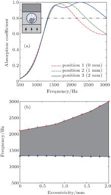
Figure 2(a) shows the comparison among the absorptances of different values of longitudinal eccentricity e of the heavy core in a frequency range of 500 Hz– 3000 Hz. Here the values of e are chosen to be 0 mm, 1 mm, and 2 mm assigned as position 1, 2, and 3 respectively. It is shown in the figure that the core position has a considerable influence on the absorption performance of the viscoelastic panel. By changing the eccentricity of the core in LRS, two different types of absorptance curves are found. For positions 1 and 2, in the absorptance spectrum there appear apparent absorption peaks around 1650 Hz and 1800 Hz respectively. For position 3, there are two absorption peaks near 1500 Hz and 2250 Hz. Comparing the three absorption curves in detail, one can find that there are few changes in the absorptance at the frequencies below 1500 Hz with increasing the longitudinal eccentricity e, however, the absorptances above 1500 Hz becomes gradually better.
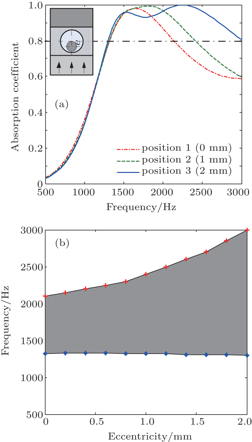 | Fig. 2. (a) Comparison among the absorptances for three core positions. The dot– dashed line, the dashed line, and the solid line represent positions 1, 2, and 3, respectively. (b) Valid absorption (with absorptance above 0.8) frequency band (VAFB) varying with longitudinal eccentricity e. |
Figure 2(b) shows the variation of valid absorption (with absorptance above 0.8) frequency band (VAFB) with eccentricity e. It can be seen that with increasing the eccentricity e, the lower frequency limit of the VAFB changes little, however, the upper frequency limit significantly increases. For position 3 (e = 2 mm), the upper limit frequency of the valid absorption band increases from 2100 Hz to 3000 Hz compared with that of position 1 (e = 0 mm). Thus, the VAFB of the viscoelastic panel becomes gradually broader as e increases.
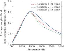
In order to clarify the mechanism for the influence of core position on the sound absorption of the viscoelastic panel, we first calculate the frequency-dependent average difference of the longitudinal displacement (ADLD) between the upper surface and lower surface of the viscoelastic panel, by using the method in Ref. [12],
where Averagex means calculating the average value along the x direction, uy denotes the y component of the displacement of the viscoelastic panel. Figure 3 shows the average displacement-difference spectra for different core positions. It can be seen that each of all curves has a displacement-difference peak near 1450 Hz, and the peak amplitudes are almost unchanged. It suggests that the largest overall deformation occurs at around 1450 Hz for all three viscoelastic panels with different core positions.
 | Fig. 3. Variations of average longitudinal displacement-difference spectra with frequency for core positions 1, 2, and 3. |
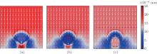
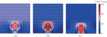
Furthermore, figure 4 shows the displacement fields of both the viscoelastic panel and the steel backing at 1450 Hz for the three different core positions. It shows that the displacement fields of the viscoelastic panel for different core positions follow the same pattern which can be called overall resonance mode (ORM).[8, 10] The steel slab and the bottom area (near the steel slab) of the viscoelastic panel show the larger displacement amplitude than that of the other portion in the panel. The displacement around the LRS changes with core position, however, the amplitude is much less than the steel slab. It suggests that the resonance absorption of the viscoelastic panel is determined mainly by the vibration of the steel backing, but not the LRSs. Therefore, as the eccentricity of the heavy core varies, there occur few differences in the sound absorption performance (around 1450 Hz in Fig. 2(a)) of the viscoelastic panel.
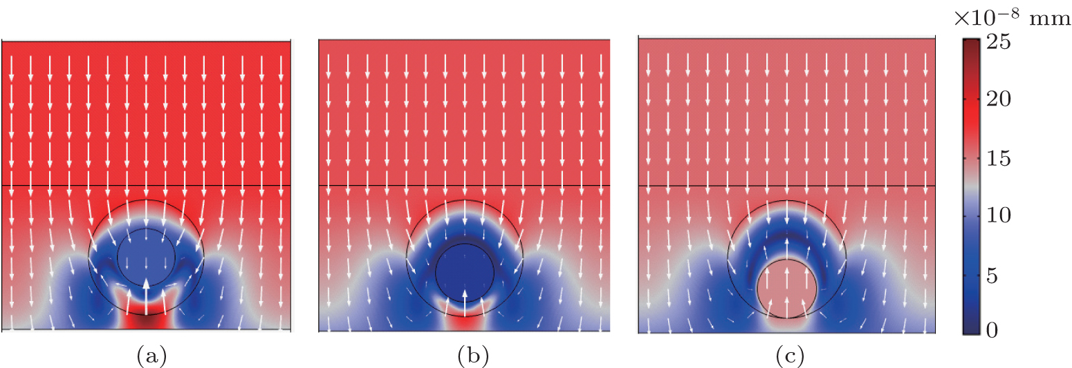 | Fig. 4. The displacement fields of both the viscoelastic panel and the steel backing at 1450 Hz for core positions 1 (a), 2 (b), and 3 (c)). The linear color bar indicates the magnitudes of the total displacements of the structures. The arrows denote the displacement vectors of the nodes of the structures, and the arrow length is scaled by the displacement amplitude. |
Comparing Fig. 2(a) with Fig. 3, one can see that only for the core position 3, the first absorption peak (near 1500 Hz) of the viscoelastic panel can agree well with the peak frequency (near 1450 Hz) of the ADLD. For positions 1 and 2, their absorption peaks occur near 1650 Hz and 1800 Hz respectively. Figures 5(a) and 5(b) show the displacement fields of the viscoelastic panel and the steel slab corresponding to these two absorption peaks. One can see that the core of LRS vibrates as a whole and has more obvious displacements than the steel slab and the rubber matrix. It shows that the LRS exhibits a rigid body resonance[9– 11] which we refer to as core resonance mode (CRM). Figure 5(c) further shows the displacement field of the viscoelastic panel at the second absorption peak (near 2250 Hz in Fig. 2(a)) for position 3. It shows that the LRS has a similar displacement pattern to the cases of positions 1 and 2, however, the displacement amplitude of the steel slab and the rubber matrix are smaller. Considering all three displacement fields in Fig. 5, it can be found that at the absorptance peak frequencies for different core positions, the displacement amplitudes in the steel slab and the rubber matrix decrease gradually with increasing the eccentricity e. Thus, for positions 1 and 2, because of the coupling effect between the CRM and ORM, in the absorptance spectra there occurs first absorption peak that is broader around each of 1650 Hz and 1800 Hz respectively, thereby leading to the peak-frequency difference between the absorptance spectrums and the ADLD. From another perspective, the steel core in conjunction with its coating layer can be considered as a spring-and-mass system.[1] With increasing the longitudinal eccentricity e of the heavy core, the effective stiffness of the coating layer of the LRS increases, then the CRM shifts toward higher frequency. In consequence, the VAFB of the panel can be broadened gradually. For example, the CRM with largest eccentricity (position 3) shifts to 2250 Hz so that it can decouple with ORM (near 1450 Hz). It results in two separate absorption peaks and then a broad VAFB forms.
 | Fig. 5. Displacement fields of both the viscoelastic panel and the steel slab corresponding to the absorption peaks of (a) 1650 Hz, (b) 1800 Hz, and (c) 2250 Hz, respectively for core positions 1, 2, and 3. |
In this paper, we study the low-frequency absorption characteristics of the viscoelastic panel which is single-periodically embedded with infinite-long non-coaxially cylindrical LRSs. The influence of the core position of the LRS on the absorption properties of the composite panel under the steel backing is investigated by using the finite element method. Different core positions are evaluated by the longitudinal eccentricity e of the core. The result shows that the core position in LRS can considerably affect the sound absorptance in the considered frequency range (500 Hz– 3000 Hz). Few changes occur in the absorptance below 1500 Hz with increasing the eccentricity e, however, the absorptance for the frequency band above 1500 Hz becomes gradually better and the VAFB (with absorptance above 0.8) is broadened accordingly. Then, the possible absorption mechanism is investigated by the displacement fields. The result shows two typical resonance modes. One is the ORM caused by steel backing, the other one is the CRM caused by LRS respectively. The absorptance of the viscoelastic panel by ORM is mainly induced by the vibration of the steel slab and affected little by the core position. On the contrary, the CRM is largely dependent on the core position of LRS. When the eccentricity is small, the effective frequencies of ORM and CRM overlap with each other, which could result in a broad absorptance peak (positions 1 and 2). With increasing the longitudinal eccentricity e, the CRM shifts toward high frequency band and decouples with the ORM gradually. Accordingly, the absorptance curve forms two absorption peaks (such as position 3) and broadens the VAFB.
| 1 |
|
| 2 |
|
| 3 |
|
| 4 |
|
| 5 |
|
| 6 |
|
| 7 |
|
| 8 |
|
| 9 |
|
| 10 |
|
| 11 |
|
| 12 |
|
| 13 |
|
| 14 |
|
| 15 |
|
| 16 |
|
| 17 |
|
| 18 |
|
| 19 |
|
| 20 |
|
| 21 |
|
| 22 | [Cited within:1] |
| 23 |
|