
Optical coherence transfer over 50-km spooled fiber with frequency instability of 2×10⁻¹⁷ at 1 s
[Ma Chao-Qun, Li-Fei Wu, Jiang Yan-Yi† , Yu Hong-Fu, Bi Zhi-Yi, Ma Long-Sheng]
, Yu Hong-Fu, Bi Zhi-Yi, Ma Long-Sheng]
 |


†Corresponding author. E-mail: yyjiang@phy.ecnu.edu.cn
*Project supported by the National Natural Science Foundation of China (Grant Nos. 11127405, 11334002, and 11374102) and the National Basic Research Program of China (Grant No. 2012CB821302).
We demonstrate coherent transfer of an ultra-stable optical frequency at 192.8 THz over 50-km spooled fiber. Random phase noise induced by environmental disturbance through fiber is detected and suppressed by feeding a correctional signal into an acousto-optic modulator. After being compensated, the fiber-induced frequency instability is 2×10⁻¹⁷ at 1-s averaging time and reaches 8×10⁻²⁰ after 16 h. The noise floor of the compensation system could be as low as 2×10⁻¹⁸ at 1-s averaging time.
The development of optical atomic clock with superior stability and accuracy paves a way for a variety of applications in many different scientific fields, including fundamental physics, [1, 2] geodesy, [3] and astronomy.[4] However, most of the applications require accurate coherent transfer of clock signals between laboratories. Conventionally, clock comparisons are carried out through global position systems (GPS) or two-way time transfer based on satellites.[5, 6] The frequency instabilities of both methods reach a level of 10− 15 after one day of measurement, which is insufficient to compare the optical atomic clocks.[7– 11] Optical fiber links that have been established all over the world provide ready-made resources both for radio frequency (RF) dissemination[12] and optical frequency transfer. The fiber-based optical frequency transfer, which presents a much lower frequency instability than other methods, has an enormous potential to be used in optical clock comparison. Foreman et al. reported an optical coherence transfer over a 32-km fiber with a frequency instability of 3× 10− 17 at 1 s.[13] Grosche et al. phase-locked fiber laser at 1542 nm to a Ca optical clock, and transferred the laser light via a 146-km-long fiber link with a fractional instability of 3× 10− 15 at 1 s, scaling to 1× 10− 19 at 3× 10⁵ s.[14] Lopez, et al. demonstrated a scheme for optical frequency dissemination in terms of cascaded fiber link based on repeater stations. The optical frequency transferred over 300 km, obtaining frequency instabilities of 3× 10− 15 at 1 s and 5× 10− 20 after 20 h.[15] In Germany, the distance for frequency transfer has been extended to 1840 km.[16] Erbium-doped fiber amplifier (EDFA) and fiber Brillouin amplifier (FBA) were employed to overcome light power attenuation. The frequency instability is 2× 10− 15 at 1 s, reaching 4× 10− 19 at 100 s, and the statistical fractional frequency uncertainty is (− 0.14± 2.6)× 10− 19.
The challenge for optical frequency transfer via fiber is random phase noise and laser power attenuation. The random phase noise is induced by environmental disturbance through fiber, which results in fiber length fluctuation. We measure the fiber noise by sending light to travel through the fiber for a round-trip, and compensate for it by feeding a correctional signal on the driving frequency of an acousto-optic modulator (AOM).[17] There are two methods to overcome laser power attenuation, i.e., amplifiers and repeater stations, as referred above. The former has the advantages of simple setup and operation without intermediate control.[18] However, the length of the fiber restricts the servo bandwidth of the compensation system, which leaves noise with Fourier frequencies beyond the servo bandwidth uncompensated.[19] The latter consists of several segments connected by repeater stations. As we have investigated, the optimal fiber length for a single segment is about 50 km, which gives considerations to both power attenuation and servo bandwidth.
In this paper, we present coherent transfer of an optical frequency of 192.8 THz (1556 nm) over a 50-km spooled fiber. The experimental setup and techniques for compensating for the fiber-induced random phase noise are described. We achieve a low system noise floor with a frequency instability of 2× 10− 18 at 1-s averaging time, which is among the lowest results that have been reported.[14, 19– 22] The frequency instability of the noise-compensated 50-km spooled fiber is 2× 10− 17 at 1-s averaging time, falling down to 8× 10− 20 after 16 h.
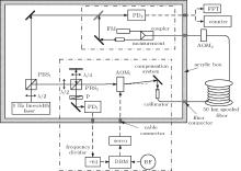
Figure 1 shows the experimental scheme for coherent optical frequency transfer. In this work, we use a commercial diode laser module (from Redfern Integrated Optics Inc.) operating at 1556 nm with a linewidth of 10 kHz. Since the clock laser in optical clock has a linewidth of sub-Hz, an ultra-narrow linewidth laser is necessary for optical coherence transfer. By using the Pound– Drever– Hall (PDH) technique, [23– 26] the laser frequency is locked to the resonance of an ultra-stable Fabry– Pé rot (FP) optical cavity made of ultra-low expansion (ULE) glass, providing a 1-Hz linewidth coherence light for transfer.
The schematic diagram of fiber noise compensation is also shown in Fig. 1. Firstly, the 1-Hz-linewidth laser light is split by PBS1 for optical frequency transfer and performance measurements, respectively. The light for optical frequency transfer goes to an interferometer, which employs a short reference arm and a long arm with a piece of 50-km spooled fiber. PBS2 and a half-wave plate (λ /2) adjust the light intensity ratio of the two arms. The light in the reference arm is directly reflected by a mirror and goes through a quarter-wave plate (λ /4) twice. Then it passes through PBS2 and is reflected to a photo detector PD1. The light in the long arm goes through AOM1 with a + 77.5-MHz frequency shift. The frequency-shifted light with an optical power of 3 mW is coupled into the 50-km spooled fiber, which is made by Corning Corporation with a total loss of 11 dB. At the remote site, the light is frequency-shifted by − 110 MHz on a fiber-pigtailed modulator AOM2, and then split into two parts by a fiber coupler (7:3). One part (30%) is used for further transfer or performance measurements in this paper; the other part (70%) is reflected by a fiber Faraday mirror (FM). The polarization of the laser light is rotated 45° for single pass the FM, and 90° for the light reflected back into the spooled fiber.[27] The FM enables the polarization of the retro-reflected light to be orthogonal to that of the input light, which makes the retro-reflected light maximally reflected by PBS2 onto PD1 to beat with the reference light, resulting in a steady and maximized beat note without any fiber polarization controller. Because the light double-passes AOM1 and AOM2 in a round trip, the frequency of the beat note generated on PD1 is 65 MHz. The presence of AOM2 ensures that the beat note on PD1 is generated by the light reflected back from the remote end instead of other sites in the fiber.[28] Because double balanced mixer (DBM) cannot distinguish phase variations beyond ± π , a frequency divider of 64 is employed to distinguish phase variations within ± 64π in the setup of 50-km spooled fiber for the improvements of dynamic range and robustness of the servo loop. And then the divided signal is mixed with an RF reference signal in a DBM to obtain an error signal. The error signal is sent to a servo system to generate an amplified correction signal applied to AOM1. On the assumption that the light experiences the same phase noise going back and forth through the fiber, the phase noise for one-way trip could be compensated for.
 | Fig. 1. Schematic setup for optical frequency transfer. Fiber-induced phase noise is detected on PD1, and is compensated by controlling the frequency of AOM1. The performance of fiber noise compensation is tested on PD2 by comparing the fiber-transferred light with the original laser light. PD, photo detector; P, polarizer; FFT, fast Fourier transformer; PBS, polarization beam splitter; FM, Faraday mirror; DBM, double balanced mixer. All the optics except the 50-km spooled fiber and AOM2 are placed in an acrylic box and all the connectors for cables and fibers are installed in the box. |
To evaluate the performance of the phase noise compensation system, we measure the light phase noise that transferred through the fiber and the frequency instability of the compensation system by comparing the transferred light with the local laser light on PD2. The frequency of the beat note on PD2 is 32.5 MHz.
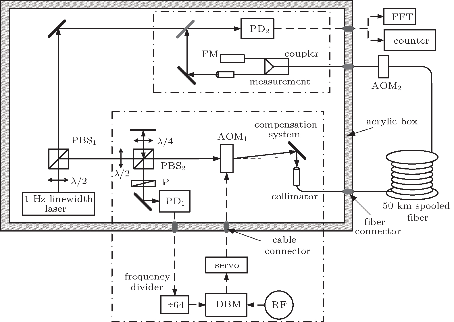
The performance of the compensation system is ultimately limited by the noise floor of the interferometer, which results largely from the noises of the uncompensated fiber and air flow. In this experiment, we make an acrylic box to protect the optics against the influence of air flow. To guarantee the sealability of the acrylic box, we inset all the connectors for cables and fibers in the box shell. The fiber coupler shown in Fig. 1 has two fiber pigtails. One is connected with a fiber FM, and the other is connected with a 0.55-m-long fiber collimator which is out of the compensation fiber link. The length fluctuation of the uncompensated fiber could result in a degradation of frequency instability for transfer. To protect the uncompensated fiber, we place it into the acrylic box and cover it with foam. We measure the noise floor of this compensation system by replacing the 50-km-long fiber with a 2-m-long fiber. The frequency of the out-of-loop signal from PD2 is recorded by a Λ -type counter (Agilent 53132A) with a gate time of 1 s, and the fractional frequency instability of the signal is expressed as Allan deviation (ADEV) which is calculated based on the recorded data. When the acrylic box is open, the ADEV is 2× 10− 16 at 1 s as shown in Fig. 2 with black solid squares. While the acrylic box is closed, the ADEV is 2× 10− 18 at 1 s, which is limited by the length fluctuation of the interferometer arms, and drops off according to 1/τ 1/2, reaching 6× 10− 20 after 1000 s. The results show that the acrylic box prevents the system from the influence of air flow and improves the frequency instability of the noise floor effectively. Moreover, when the acrylic box is closed, the phase noise power spectral density (PSD) of the 2-m-long fiber is approximately 10− 6/f rad2/Hz from 1 Hz to 1 kHz as shown with black short dashed line in Fig. 3. Here f denotes the Fourier frequency.
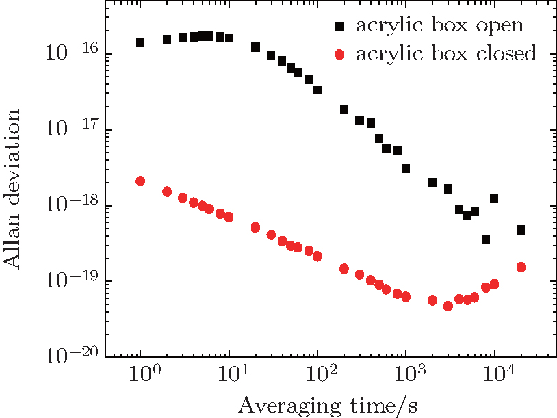 | Fig. 2. Frequency instability measurement of the compensation system noise floor when the acrylic box is open (black solid squares) and closed (red solid circles). |
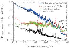
The phase noise PSDs of the 50km-long fiber with and without noise compensation are also measured, as shown with the red dashed line and blue solid line respectively in Fig. 3. The phase noise of the uncompensated 50km-long fiber exhibits a relationship with Fourier frequency as h/f2 in the Fourier frequency range of 1 Hz– 100 Hz. The coefficient h varies with fiber length. In our work, the value of h is about 230 rad2 · Hz. The integrated phase noises from 0.1 Hz to 10 kHz equal 55.1 rad and 1.2 rad, when the fiber noises are without and with compensation, respectively. The performance of the compensation system is limited by the delay effect due to the length of the fiber. As light transmits through a fiber, the single-pass delay time is τ = nL/c, where n = 1.468 is the refractive index of the fiber, and L is the length of the fiber. The error signal used for noise compensation is later than the occurring of phase noise. As a result, the fiber phase noise cannot be fully suppressed even if a perfect compensation system is used. The servo bandwidth is limited within 1/4τ .[21] As for the 50-km-long spooled fiber in this work, the single-pass delay time is about 0.25 ms. Thus the servo bandwidth is limited to around 1 kHz, corresponding to the peak at 850 Hz in Fig. 3. In an ideal condition, the compensated one-way phase noise S′ (f) can be expressed as[21]

where S(f) is the phase noise of the uncompensated fiber, and a = 1/3 for the uniformly distributed noise here. As shown in Fig. 3, the phase noise after being compensated coincides with the theoretical phase noise calculated from Eq. (1).
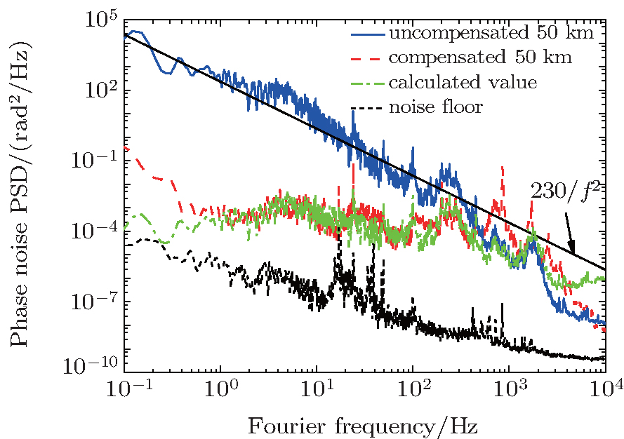 | Fig. 3. Phase noise power spectral density of uncompensated 50km-long fiber (blue solid line), compensated 50km-long fiber (red dashed line), calculated compensated 50km-long fiber (green dash dotted line), and interferometer phase noise floor (black short dash line). |
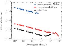
Figure 4 shows the factional frequency instabilities of the 50km-long spooled fiber without and with noise compensation. For the uncompensated fiber, the ADEV is 7× 10− 14 at 1-s averaging time, and drops off according to 1/τ 1/2. After phase noise is compensated, the ADEV is 2× 10− 17 at 1 s, and scales down as 1/τ 1/2, reaching 8× 10− 20 after 16 h. According to Refs. [20] and [29], the frequency instability of compensated fiber can be predicted from
where t is the averaging time, and ν is the optical carrier frequency. As for the 50km-long spooled fiber, in an averaging time of t = 1 s, σ is calculated to be 3.2× 10− 17 based on Eq. (2), which is in good agreement with the experimental value of 2× 10− 17.
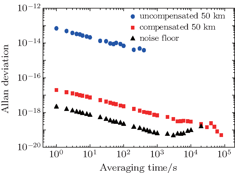 | Fig. 4. Factional frequency instabilities of the uncompensated 50km fiber (blue circle), the compensated 50-km-long fiber (red solid squares), and the interferometer noise floor (black triangle). |
We demonstrate an optical frequency transfer via a 50-km-long spooled fiber. The fiber phase noise is suppressed based on dynamic feedback control, which enables optical frequency to be disseminated over a long distance without degradation of frequency stability. The frequency instability of the system noise floor is as low as 2× 10− 18 at 1-s averaging time. After the fiber noise is compensated, the frequency instability is 2× 10− 17 at 1 s and falls down to 8× 10− 20 at 16 h. The results illustrate that this technique can be used for remote comparison of optical atomic clocks. We are planning to install repeater stations to extent the fiber length for frequency transfer.
| 1 |
|
| 2 |
|
| 3 |
|
| 4 |
|
| 5 |
|
| 6 |
|
| 7 |
|
| 8 |
|
| 9 |
|
| 10 |
|
| 11 |
|
| 12 |
|
| 13 |
|
| 14 |
|
| 15 |
|
| 16 |
|
| 17 |
|
| 18 |
|
| 19 |
|
| 20 |
|
| 21 |
|
| 22 |
|
| 23 |
|
| 24 |
|
| 25 |
|
| 26 |
|
| 27 |
|
| 28 |
|
| 29 |
|