Guo Hui-Qiang, Tang Wei-Yue†, Liu Liang, Wei Jian‡, Li Da-Lai, Feng Jia-Feng, Han Xiu-Feng. Low frequency noise in asymmetric double barrier magnetic tunnel junctions with a top thin MgO layer. Chinese Physics B, 24(7): 078504
Permissions
Low frequency noise in asymmetric double barrier magnetic tunnel junctions with a top thin MgO layer
Guo Hui-Qianga), Tang Wei-Yue†a), Liu Liangb),c), Wei Jian‡b),c), Li Da-Laid), Feng Jia-Fengd), Han Xiu-Fengd)
School of Physics and Engineering, Zhengzhou University, Zhengzhou 450001, China
International Center for Quantum Materials, School of Physics, Peking University, Beijing 100871, China
Collaborative Innovation Center of Quantum Matter, Beijing, China
Beijing National Laboratory of Condensed Matter Physics, Institute of Physics, Chinese Academy of Sciences, Beijing 100190, China
*Project supported by the National Basic Research Program of China (Grant Nos. 2011CBA00106, 2012CB927400, 2010CB934401, and 2014AA032904), the National High Technology Research and Development Program of China (Grant No. 2014AA032904), and the National Natural Science Foundation of China (Grant Nos. 11434014 and 11104252).
Abstract
Low frequency noise has been investigated at room temperature for asymmetric double barrier magnetic tunnel junctions (DBMTJs), where the coupling between the top and middle CoFeB layers is antiferromagnetic with a 0.8-nm thin top MgO barrier of the CoFeB/MgO/CoFe/CoFeB/MgO/CoFeB DBMTJ. At enough large bias, 1/f noise dominates the voltage noise power spectra in the low frequency region, and is conventionally characterized by the Hooge parameter αmag. With increasing external field, the top and bottom ferromagnetic layers are aligned by the field, and then the middle free layer rotates from antiparallel state (antiferromagnetic coupling between top and middle ferromagnetic layers) to parallel state. In this rotation process αmag and magnetoresistance-sensitivity-product show a linear dependence, consistent with the fluctuation dissipation relation. With the magnetic field applied at different angles ( θ) to the easy axis of the free layer, the linear dependence persists while the intercept of the linear fit satisfies a cos( θ) dependence, similar to that for the magnetoresistance, suggesting intrinsic relation between magnetic losses and magnetoresistance.
PACS:
85.75.–d; 73.50.Td; 75.60.Jk
Keyword:
magnetic tunnel junctions; double barrier magnetic tunnel junctions; 1/f noise; fluctuation dissipation relation
Since the magnetic tunnel junctions have potential applications in magnetic random access memory and other magnetic devices, [1] extensive experimental investigates have been done for single barrier magnetic tunnel junctions (SBMTJs).[2, 3] Recently double barrier magnetic tunnel junctions (DBMTJs) have also drawn attention for possible advantages over SBMTJs.[4– 9] In the simplest case, they can be regarded as two SBMTJs in series, [10, 11] so larger output voltage can be generated, which improves signal noise ratio.
The intrinsic low frequency noise is a performance-limiting factor for both SBMTJs and DBMTJs, and consists of 1/f noise, shot noise and thermal noise, where shot noise and thermal noise are independent of frequency. At large bias, 1/f noise dominates in the low frequency region of the noise power spectra, and it is originated from the thermally activated fluctuations of the magnetization of the ferromagnetic layers. For MTJs, 1/f noise is commonly characterized by the Hooge-like parameter: , [12] where A is the junction area, f is the frequency, is the noise power spectral density, and V is the voltage applied to the device. With the quasi-equilibrium assumption, the magnetic 1/f noise originates from thermal magnetization fluctuations can be related to the imaginary component of the magnetic susceptibility through the fluctuation dissipation relation (FDR)[12]
where Δ R = RAP − RP, RP (RAP) is the parallel (antiparallel) resistance, [13]μ 0Ms is the saturation magnetization of magnetic layers (1.6 T for Co40Fe40B20), kB is Boltzmann’ s constant, T is the absolute temperature, and μ 0 is the vacuum permeability. The magnetoresistance-sensitivity-product is defined as MSP ≡ (Δ R/R2)(dR/dH). Equation (1) indicates that α mag is proportional to MSP, and the phase lag ε (f, H), which depends on material properties, can be estimated from the measured α mag and MSP.[14] In this work we vary the angle between the applied field and the easy axis of the free layer, and measure α mag and MSP at different angles.
2. Experimental methods
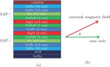
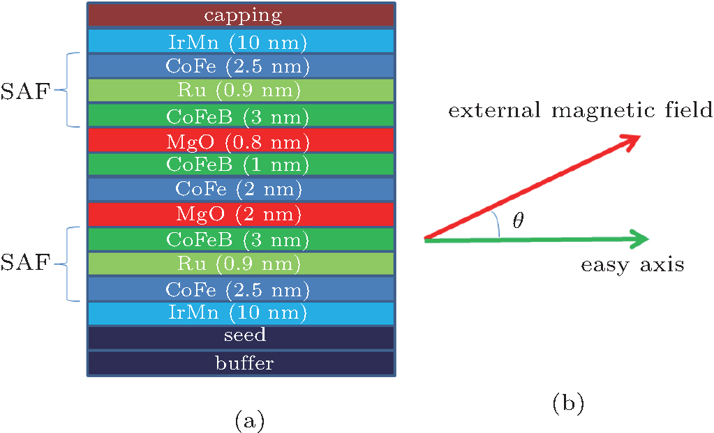
Schematic diagram of asymmetric DBMTJ stack is shown in Fig. 1(a). The structure is: Ta 5/Ru 30/Ta 5/Ni81Fe19 5/Ir22Mn78 10/Co90Fe10 2.5/Ru 0.9/Co40Fe40B20 (CoFeB) 3/MgO 2/Co50Fe50 (CoFe) 2/CoFeB 1/MgO 0.8/CoFeB 3/Ru 0.9/Co90Fe10 2.5/Ir22Mn78 10/Ni81Fe19 5/Ta 5/Ru 5 (all thicknesses in nm). The junction size is about 5 × 10 μ m2, and the devices were annealed at 350 ° C under an external in-plane magnetic field 800 mT for half an hour. Detailed information of sample fabrication can be found in Ref. [9].
Fig. 1. (a) Schematic diagram of the stack of asymmetric double barrier magnetic tunnel junction (DBMTJ). (b) Illustration of angle θ between the easy axis and the external magnetic field. The easy axis direction in the figure is the positive direction.
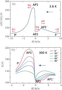
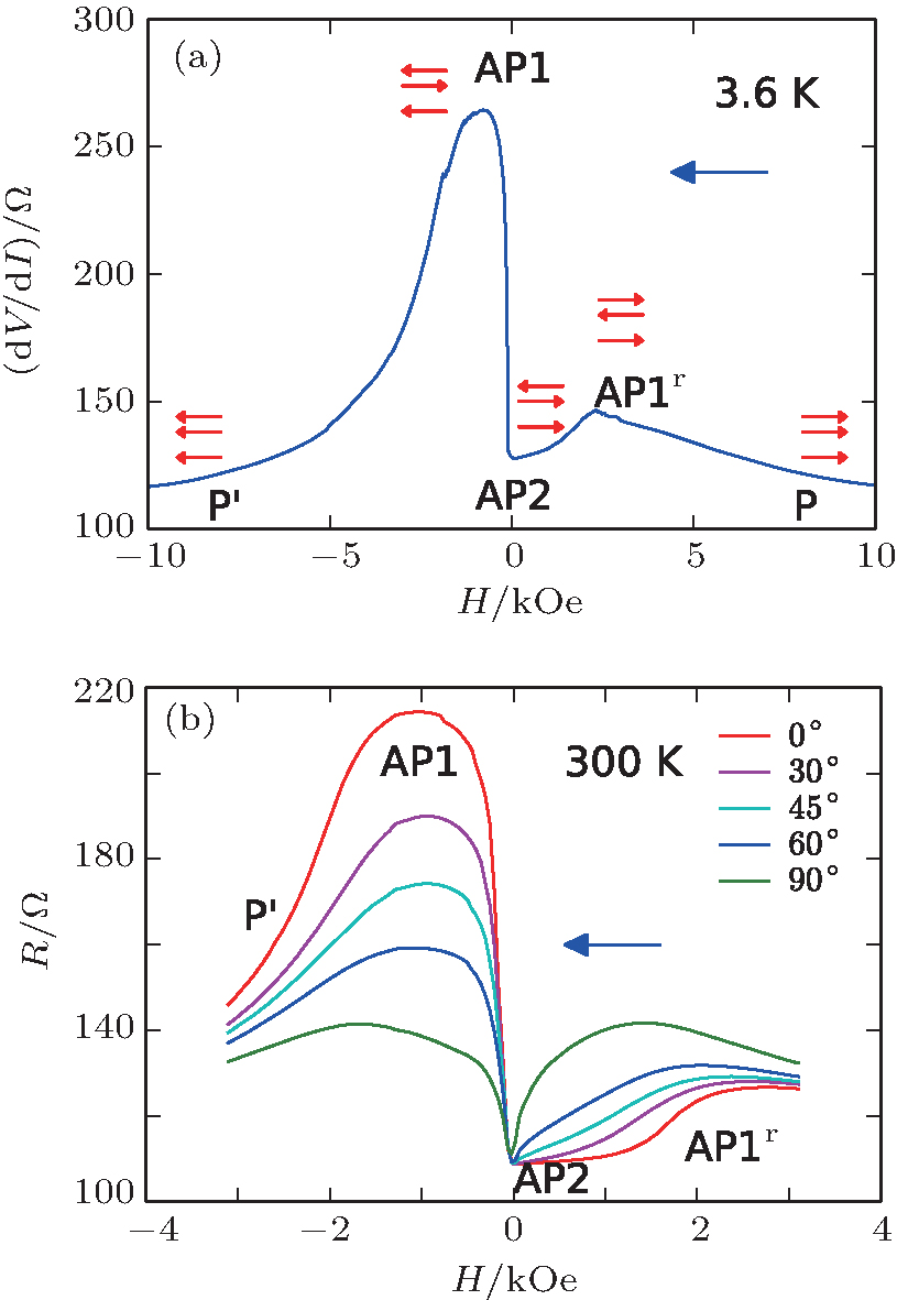
Field dependence of dV/dI at 3.6 K is measured by standard lock-in technique with zero DC bias, as shown in Fig. 2(a), with different magnetic states denoted. The low frequency noise and static magnetoresistance at room temperature are measured using conventional four-terminal DC method with a large fixed DC current 1.3 mA, as shown in Fig. 2(b). The magnetic field is produced by a vector superconducting magnet at 3.6 K and a electromagnet at room temperature respectively. To avoid extrinsic noises for the noise measurements, the DC current is produced by battery and ballast resistors. The voltage fluctuation signal is AC coupled to a home-made ultra-low noise amplifier with its own noise about and the output is digitized with a data acquisition card. For field dependence of the noise measurement, the step of the applied field is 40 Oe and the stabilization time before the noise measurement is long enough to ensure the device in a quasi-equilibrium state. The sweeping direction of the magnetic field is in plane and from positive to negative, as shown in Fig. 1(b).
Fig. 2. (a) Magnetoresistance (MR) curve in DBMTJs at 3.6 K with one very thin top barrier, resulting in the coupling between the top and central magnetic layers. The magnetic states from right to left are P(↑ ↑ ↑ ), AP1r(↑ ↓ ↑ ), AP2(↑ ↑ ↓ ), AP1(↓ ↑ ↓ ), and P′ (↓ ↓ ↓ ), respectively. (b) Static MR at room temperature with different θ between the easy axis and the external magnetic field. The blue arrow indicates the field sweeping direction.
3. Results and discussion
As explained in previous findings, [6, 7, 15] the antiferromagnetic coupling between two ferromagnetic layers across the top thin MgO barrier in DBMTJs results in two different AP states: AP1 (↓ ↑ ↓ ) and AP1r (↑ ↓ ↑ ), in which the middle free layer’ s magnetization is aligned opposite to the neighbouring ones, as depicted in Fig. 2(a) following Ref. [7]. Although the asymmetric DBMTJ in the previous work is made of epitaxial Fe/MgO/Fe/MgO/Fe stack and does not have synthetic anti-ferromagnetic layers (SAF) as shown in Fig. 1, the similarity of the magnetoresistance suggests that the magnetic configurations are similar, so the nomenclature of the magnetic configurations in the previous work is followed.
The difference in resistance between the AP1(↓ ↑ ↓ ) and AP1r(↑ ↓ ↑ ) states was already observed and was attributed to the possible influence of domain walls formed in the synthetic antiferromagnet.[7] Here, the difference in resistance could be more naturally explained by the different coupling between the SAF and the IrMn AF layer, i.e., for AP1 state the AF layer can pin the SAF, while for AP1r the AF layer does not pin the SAF, due to the unidirectional anisotropy introduced by the AF layers.[16] The magnetoresistance dip between AP1 and AP1r corresponds to the AP2 (↑ ↑ ↓ ) state. The two parallel states are P (↑ ↑ ↑ ) and P′ (↓ ↓ ↓ ) state from right to left respectively, for which the magnetization of three CoFeB layers align along one direction, and at 10 kOe the dV/dI of P and P′ states is slightly smaller than that of the AP2 state.
The static magnetoresistance at different θ at room temperature is shown in Fig. 2(b). As θ increases, the resistance peak at AP1 state decreases and moves towards the negative direction, while the field range of AP2 state shrinks and the peak of AP1r also moves towards the negative direction. And finally the MR is close to symmetric when θ is 90° . The smaller range of the field in Fig. 2(b) is due to the limit of our electromagnet.
In our previous reports of low frequency noise in SBMTJs[17] and symmetrical DBMTJs, [11] we did not focus on the regime where the free layer flips since it is a very narrow regime close to zero field. Here, as show by the magnetic configurations in Fig. 2, the middle free layer flips three times from right to left, and in the field range from AP1 to P′ state the resistance decreases gradually, which is suitable for noise measurement. Since only the free layer is undergoing magnetic reversal, while the upper and bottom CoFeB layers in DBMTJ are effectively pinned, this regime seems to be a simplified case for applying the FDR and Eq. (1).
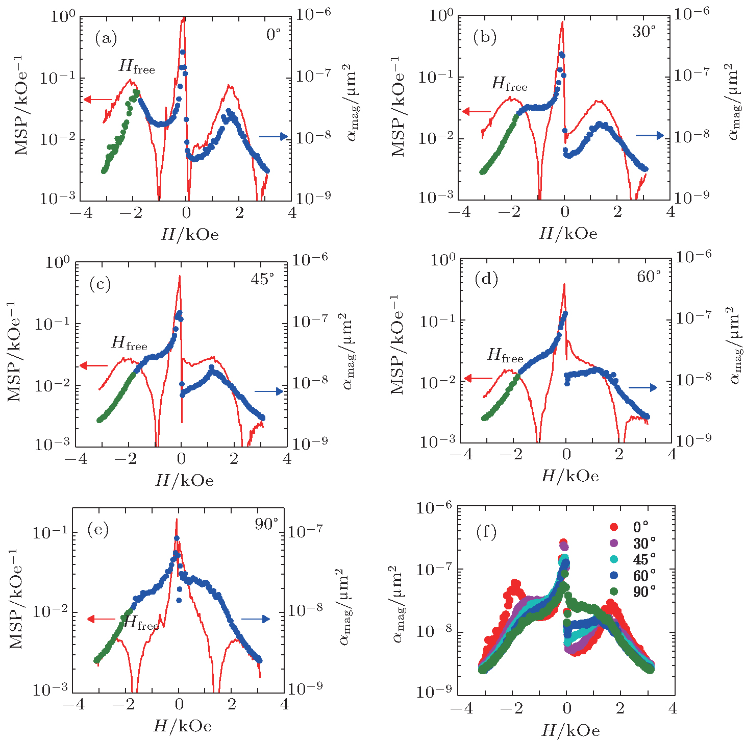
At 1.3 mA, the voltage noise power spectra is dominated by 1/f noise from 1 Hz to 50 kHz, and the retrieved α mag and MSP are shown in Fig. 3(a)– 3(e) for different angles. For θ = 0° , α mag exhibits three peaks from right to left corresponding to magnetic configuration transitions from AP1r to AP2, AP2 to AP1, and AP1 to P′ respectively. As expected, in the left side of the far left α mag peak (from about − 2 to − 3 kOe), FDR seems to be applicable. With increasing θ , AP1 and AP1r states become more symmetric and AP1r state moves towards zero field, until θ = 90° where AP1 and AP1r have similar resistance and both MSP and α mag are symmetric to zero.
Fig. 3. Hooge parameter (circles) and magnetoresistance-sensitivity-product (solid line) versus magnetic field at each angle are shown in panels (a)– (e). Hfree denotes the peak position of MSP in negative field region. Our focused regions are shown by green circles. α mag versus magnetic field of each angle is plotted in panel (f). The measurement is carried out at room temperature.
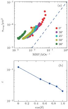
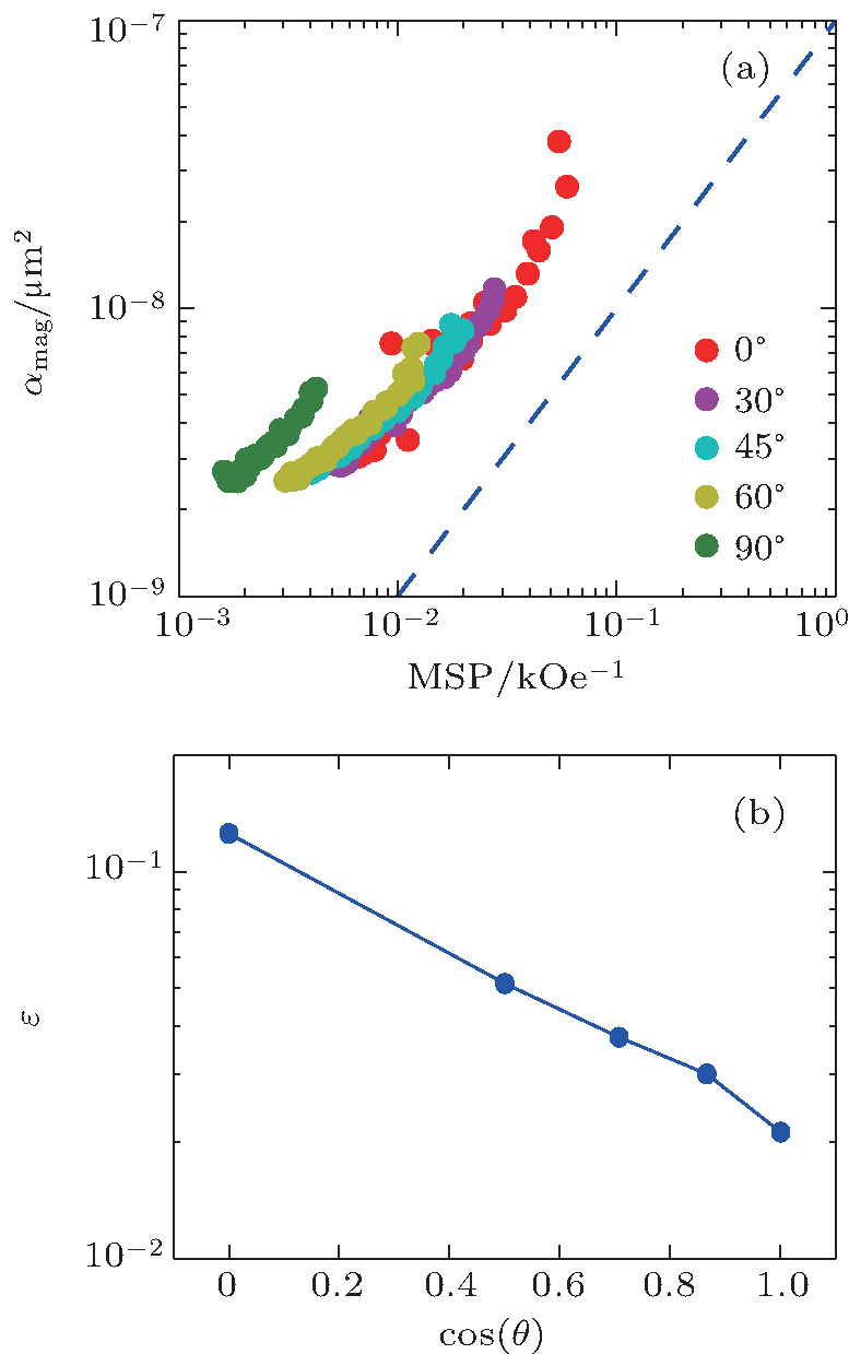
Having determined α mag and MSP, the phase lag ε (f, H) can be estimated following Eq. (1), and in the field region where only free layer rotates ε should be a constant if α mag and MSP are linearly related. Indeed, when α mag is plotted as a function of MSP in Fig. 4(a), the linearity is observed in the field region below Hfree, which is the peak position of MSP, as shown in Fig. 3(a)– 3(e). In this region, free layer’ s magnetization rotate from antiparallel to parallel, as indicated in Fig. 2(a), thus the source of magnetic 1/f noise may relate to domain motion and rotation in the middle free layer. Figure 3(f) shows that α mag decreases in the field region below Hfree for all angles, and in the deep P′ and P states may converge to the field independent barrier noise.[17]
Fig. 4. (a) The relation between α mag and MSP plotted in panel (f). The slope of the scaling between α mag and MSP is close to 1, which can be illustrated by the dashed blue line. (b) The logarithm of the phase lag log (ε ) is inversely proportional to cos(θ ).
The fitted slopes and intercepts are listed in Table 1. The fitted slopes are close to 1, consistent with the quasi-equilibrium assumption. ε (f, H) can be deduced from the intercept and is found to increase with the angle. Figure 4(b) shows that log (ε ) has a roughly linear dependence on cos(θ ). It is interesting to note that similar θ dependence is expected for conductivity of a standard SBMTJ: G = acos(θ ) + b, [18] where θ is the angle between external magnetic field direction and free layer magnetization orientation, a and b are parameters related to the device. This may suggest an intrinsic correlation between spin rotation and magnetic losses and further investigation is required.
Table 1.
Table 1.
Table 1. The fitted slopes and intercepts at different angles based on Fig. 4(a).
Angle
0°
30°
45°
60°
90°
Slope
1.041
0.991
1.012
1.004
0.998
Intercept
10− 9.757
10− 9.607
10− 9.512
10− 9.373
10− 8.985
Table 1. The fitted slopes and intercepts at different angles based on Fig. 4(a).
4. Conclusion
In summary, low frequency noise has been studied for asymmetric DBMTJs at different angle θ between the easy axis and the external magnetic field. The α mag is linearly proportional to the MSP for the field range where only the middle free layer rotates, consistent with the fluctuation dissipation theorem for thermal magnetization fluctuations. The logarithm of the phase lag monotonically increases as θ increases and is inversely proportional to cos(θ ), which resembles the θ dependence of the MTJ conductivity.
Acknowledgment
We thank J. M. D. Coey for collaboration on sample fabrication.
CascalesJ P, HerranzD, AlievF G, SzczepańskiT, DugaevV K, BarnaśJ, DuluardA, HehnM and TiusanC2012Phys. Rev. Lett. 109066601DOI:10.1103/PhysRevLett.109.066601[Cited within:3]
8
LiuR S, YangS H, JiangX, ZhangX G, RettnerC, GaoL, TopuriaT, RiceP M, ZhangW, CanaliC M and ParkinS S P2013Phys. Rev. B87024411DOI:10.1103/PhysRevB.87.024411[Cited within:1]
9
LiD L, FengJ F, YuG Q, GuoP, ChenJ Y, WeiH X, HanX F and CoeyJ M D2013J. Appl. Phys. 114213909DOI:10.1063/1.4838116[Cited within:2]
10
FengG, van DijkenS, FengJ F, CoeyJ M D, LeoT and SmithD J2009J. Appl. Phys. 105033916DOI:10.1063/1.3068186[Cited within:1]
11
YuG Q, DiaoZ, FengJ F, KurtH, HanX F and CoeyJ M D2011Appl. Phys. Lett. 98112504DOI:10.1063/1.3562951[Cited within:2]
12
OzbayA, GokceA, FlanaganT, StearrettR A, NowakE R and NordmanC2009Appl. Phys. Lett. 94202506DOI:10.1063/1.3139067[Cited within:2]
13
Here we use Δ R = RAP1 − RAP2 since at room temperature R P can not be determined, which may affect the constant prefactor but have small influence on calculating MSP and determination of ε[Cited within:1]
14
StearrettR, WangW G, KouX, FengJ F, CoeyJ M D, XiaoJ Q and NowakE R2012Phys. Rev. B86014415DOI:10.1103/PhysRevB.86.014415[Cited within:1]
15
Faure-VincentJ, TiusanC, BellouardC, PopovaE, HehnM, MontaigneF and SchuhlA2002Phys. Rev. Lett. 89107206DOI:10.1103/PhysRevLett.89.107206[Cited within:1]
16
NegulescuB, LacourD, MontaigneF, GerkenA, PaulJ, SpetterV, MarienJ, DuretC and HehnM2009Appl. Phys. Lett. 95112502DOI:10.1063/1.3226676[Cited within:1]
17
FengJ, DiaoZ, KurtH, StearrettR, SinghA, NowakE R and CoeyJ M D2012J. Appl. Phys. 112093913DOI:10.1063/1.4764314[Cited within:2]
18
LiuL, NiuJ, XiangL, WeiJ, LiD L, FengJ F, HanX F, ZhangX G and CoeyJ M D2014Phys. Rev. B90195132DOI:10.1103/PhysRevB.90.195132[Cited within:1]
1
2007
0.0
0.0
... IntroductionSince the magnetic tunnel junctions have potential applications in magnetic random access memory and other magnetic devices,[1] extensive experimental investigates have been done for single barrier magnetic tunnel junctions (SBMTJs) ...
1
2004
0.0
0.0
... [2,3] Recently double barrier magnetic tunnel junctions (DBMTJs) have also drawn attention for possible advantages over SBMTJs ...
1
2004
0.0
0.0
... [2,3] Recently double barrier magnetic tunnel junctions (DBMTJs) have also drawn attention for possible advantages over SBMTJs ...
1
2006
0.0
0.0
... [4#cod#x2013 ...
1
2006
0.0
0.0
1
2007
0.0
0.0
... Results and discussionAs explained in previous findings,[6,7,15] the antiferromagnetic coupling between two ferromagnetic layers across the top thin MgO barrier in DBMTJs results in two different AP states: AP1 (#cod#x2193 ...
3
2012
0.0
0.0
... Results and discussionAs explained in previous findings,[6,7,15] the antiferromagnetic coupling between two ferromagnetic layers across the top thin MgO barrier in DBMTJs results in two different AP states: AP1 (#cod#x2193 ...
... [7] ...
... [7] Here, the difference in resistance could be more naturally explained by the different coupling between the SAF and the IrMn AF layer, i ...
1
2013
0.0
0.0
2
2013
0.0
0.0
... 9] In the simplest case, they can be regarded as two SBMTJs in series,[10,11] so larger output voltage can be generated, which improves signal noise ratio ...
... [9] ...
1
2009
0.0
0.0
... 9] In the simplest case, they can be regarded as two SBMTJs in series,[10,11] so larger output voltage can be generated, which improves signal noise ratio ...
2
2011
0.0
0.0
... 9] In the simplest case, they can be regarded as two SBMTJs in series,[10,11] so larger output voltage can be generated, which improves signal noise ratio ...
... In our previous reports of low frequency noise in SBMTJs[17] and symmetrical DBMTJs,[11] we did not focus on the regime where the free layer flips since it is a very narrow regime close to zero field ...
2
2009
0.0
0.0
... For MTJs, 1/f noise is commonly characterized by the Hooge-like parameter: ,[12] where A is the junction area, f is the frequency, is the noise power spectral density, and V is the voltage applied to the device ...
... With the quasi-equilibrium assumption, the magnetic 1/f noise originates from thermal magnetization fluctuations can be related to the imaginary component of the magnetic susceptibility through the fluctuation dissipation relation (FDR)[12] ...
1
0.0
0.0
... RP, RP (RAP) is the parallel (antiparallel) resistance,[13]#cod#x03BC ...
1
2012
0.0
0.0
... [14] In this work we vary the angle between the applied field and the easy axis of the free layer, and measure #cod#x03B1 ...
1
2002
0.0
0.0
... Results and discussionAs explained in previous findings,[6,7,15] the antiferromagnetic coupling between two ferromagnetic layers across the top thin MgO barrier in DBMTJs results in two different AP states: AP1 (#cod#x2193 ...
1
2009
0.0
0.0
... [16] The magnetoresistance dip between AP1 and AP1r corresponds to the AP2 (#cod#x2191 ...
2
2012
0.0
0.0
... In our previous reports of low frequency noise in SBMTJs[17] and symmetrical DBMTJs,[11] we did not focus on the regime where the free layer flips since it is a very narrow regime close to zero field ...
... [17] ...
1
2014
0.0
0.0
... b,[18] where #cod#x03B8 ...
Low frequency noise in asymmetric double barrier magnetic tunnel junctions with a top thin MgO layer
[Guo Hui-Qianga), Tang Wei-Yue†a), Liu Liangb),c), Wei Jian‡b),c), Li Da-Laid), Feng Jia-Fengd), Han Xiu-Fengd)]


 , Liu Liang