1. IntroductionOne of the most representative polymer solar cells (PSC) is the bulk heterojunction (BHJ) device based on a blend of poly(3-hexylthiophene) (P3HT) as an electron donor and [6, 6]-phenyl-C 61-butyric acid methyl ester (PC61BM), which is a soluble C60 derivative, as an electron acceptor. The power conversion efficiency (PCE) of this type of cells based on P3HT: PC61BM has reached 4%– 6%[1– 9] by optimization and control of the morphology of the BHJ blends. The morphology of the photoactive layer of BHJ polymer solar cells (PSC) is critically important for achieving the high PCE. The proper morphology provides not only an enough interface with a high-separation force for exciton dissociation, but also the continuity and correct interpenetrating network for effective transport of electrons and holes. A precondition to optimize the morphology of BHJ blend for getting a good lamellar orientation and suitable domain size is good miscibility of the two materials, which is an inherent characteristic of the materials used and also depends on the solvent used.[10, 11] It is considered that efficient charge transport from phase to phase requires good relative alignment between adjacent ordered crystalline regions. The performance of P3HT films depends on the highly textured and oriented crystallites nucleated from the buried interface.[12] In P3HT self-organized lamellar nanoscale crystalline regions, the hole charge mobility is greatest in the backbone direction, lower in the π -stacking direction (conduction by hopping) and negligible in the alkyl direction.[13] Due to the highly anisotropic mobility, a preferred morphology should guarantee that the photo-generated charges have effective transport pathways with high mobility. Furthermore, efficient charge transportation will occur via charge hopping through polymer chain bridges[14] between crystalline domains, [15] and percolation pathways will be formed along the vertical structure. The as-spun blend of P3HT and PC61BM has been described as a ternary system made of amorphous P3HT, crystalline P3HT, and PC61BM aggregates.[16] In reality, lamellar P3HT shows a complex phase structure, where crystalline domains are surrounded by a significant amount of amorphous P3HT.[17, 18]
There are more methods to improve the morphology of polymer:fullerene BHJ materials, for example, thermal annealing, [2, 19– 22] solvent annealing, [4, 23] and the use of processing additives.[24– 28] Grazing incidence x-ray diffraction (GIXRD) has been proven to be a powerful tool for investigating the nano-morphology of polymer-fullerene bulk heteojunction blends under different conditions. Results of 2D grazing incidence x-ray diffraction (2D-GIXRD) provide the evidence that the solvent evaporation rate influences the polymer chain arrangement of the film directly.[16, 18, 21, 29– 36] Sanyal et al. employed in-situ GIXRD to investigate the crystallization behavior of P3HT: PC61BM blends cast by doctor blading.[31, 37] By using out-of-plane and in-plane GIXRD, Aryal et al. reported the use of nanoimprint lithography to fabricate large-area, high-density ordered nanostructures in conjugated polymer poly(3-hexylthiophene) or P3HT, and to simultaneously control 3D chain alignment within these P3HT nanostructures.[32] Furthermore, when 2D GIWAXS patterns were collected, it was found that the P3HT self-organized texture depends on thermal annealing[13, 21, 38] and solvent treatments like solvent addition.[39, 40] However, the main factors that influence the blend morphology and how the blend morphology changes during the treatments are still unknown.
In the present paper, we particularly show the mechanism of morphology forming by comparing different paracrystalline disorder in P3HT:PC61BM blends in the course of thermal annealing and adding solvent additive 1, 8-diiodooctane(DIO) using the 2D-GIXRD technique. The interpretation of the diffraction patterns of P3HT:PC61BM thin film is well documented, including crystal packing and orientation information. Controlling the blend morphology is critical for improving the optical and electrical properties of organic bulk heterojunction photovoltaic devices. It is necessary to characterize the orientation distribution or texture of the crystallites in the photoactive layer correctly and comprehensively. We quantify the disorder and show that the interplanar spacing narrows much more after adding DIO solvent additive than after thermal annealing, accompanied by a concomitant change in misorientation angel of the P3HT lamellae. The coherence length of the P3HT crystallites increases in the course of both treatments. The results show that DIO solvent additive has a different effect on polymer packing and crystallization of P3HT lamellae with thermal annealing; however, both of the treatments can enhance the performance of the polymer solar cell. This study is complementary to our earlier studies.
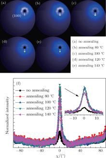
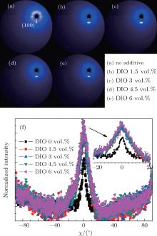
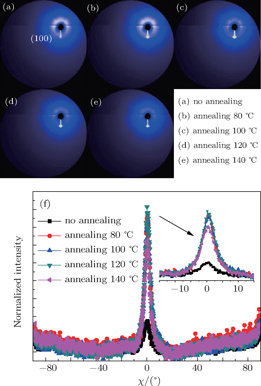
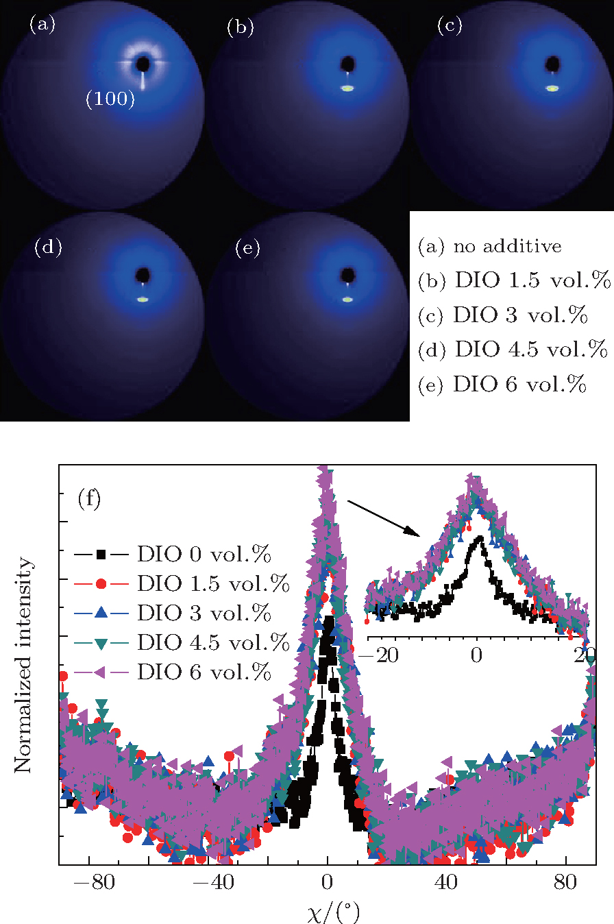
3. Results and discussionA group of 2D-GIXRD images of P3HT:PC61BM blend film with or without thermal annealing and with or without solvent additive DIO is shown in Figs. 4 and 5. It is found that the film without a preferred crystallographic orientation will result in a uniform ring-like distribution, as shown in Figs. 4(a)– 4(c) and Fig. 5(a). For the film with a preferred out-of-plane orientation but an isotropic in-plane (a textured film), the diffraction intensity pattern will contain spot-like or arc-like distribution, as shown in Figs. 4 and 5, depending on the spread of the crystallite orientation distribution.[41, 42] It can be clearly observed that the intensity spots are located near the qz direction of the 2D detector and contain the film crystalline (h00) information in the direction perpendicular (qz, out-of-plane profile) to the substrate, as shown in Figs. 4 and 5. In this case, the 2D-GIXRD data of the P3HT:PC61BM blend indicates that the P3HT in this blend film is predominantly in a paracrystalline order. In addition, the ring-like distribution readily vanishes with increasing annealing temperature and the signal along qz becomes significantly more intense upon annealing or adding DIO, showing increased polymer packing and crystallinity.
The difference of GIXRD intensities shown in Figs. 4 and 5 arises from the varied angular distribution of crystallites of films with different textures and not from the different degree of crystallinity.[11] In order to better understand about the structural evolution with different thermal annealing temperatures and solvent additive DIO concentrations, the distribution of the (100) scattered intensity as a function of the azimuthal angle χ of the detector shown in Fig. 4(f) and Fig. 5(f) is analyzed. The polar angle χ is defined as the angle between the scattering vector and the substrate’ s normal direction. The integrated intensity of a diffraction spot is proportional to, among other factors, the crystalline degree of the corresponding film illuminated by the x-ray beam.[41] Compared to the untreated blend film, it is found that both the thermal annealing and DIO additive treatment increase the relative crystallinity degree. However, the (100) diffraction peak of films treated by DIO additive is broader than that of annealed films. This means that the spot-like diffraction is less intense than that of the annealed BHJ blend film.
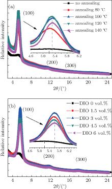
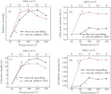
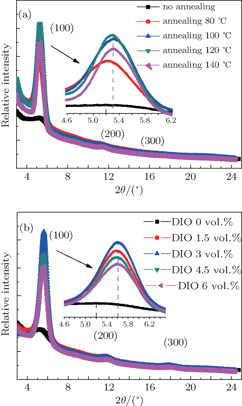
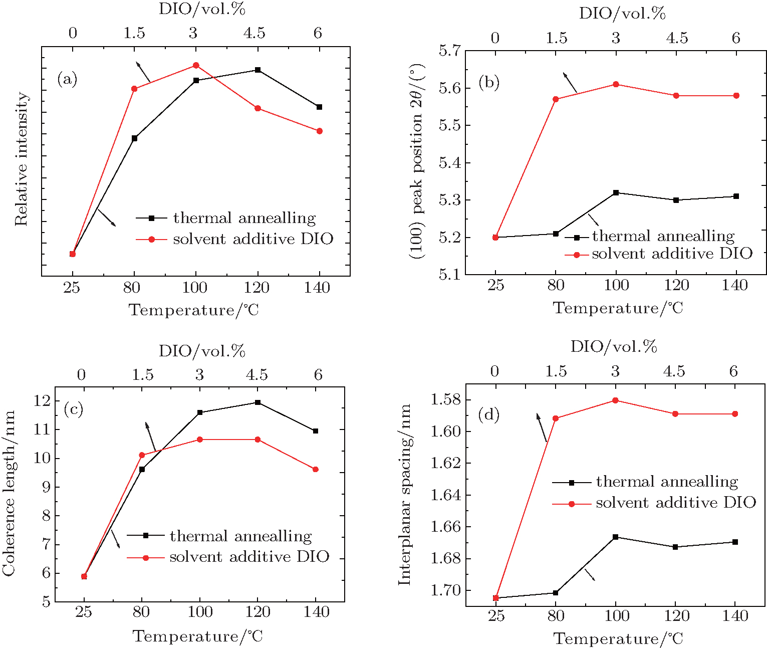
In order to investigate the effect of different treatments further, out-of-plane (OOP) GIXRD of different P3HT: PC61BM blend films were recorded. The GIXRD results quantify the extent of the P3HT crystallization in the different blends. The OOP line profiles of 2D-GIXRD image are shown in Fig. 6. A diffraction peak at 2θ = 5.2° is observed clearly. According to the model proposed by Kayunkid et al.[30] the diffraction peak at 2θ = 5.2° corresponds to the crystal face of (100) of P3HT. This means the main chains of P3HT are parallel to the substrate and the side chains are perpendicular to it. In addition, two weak peaks corresponding to (200) and (300), at 2θ = 10.4° and 16° respectively, are also detected in samples treated by either annealing and DIO adding. There are no diffraction peaks corresponding to the crystalline PCBM in the as-spun blends in Fig. 6, which agrees with other studies.[16, 21, 29, 30] The combination of OOP diffraction peaks of (100), (200), and (300) of P3HT provides information about the diffraction peak position, diffraction peak intensity, the coherence length, and the interplanar spacing (see Fig. 7), respectively, for the edge-on lamellae P3HT. A strong (h00) series of three-order diffraction peaks ((100), (200), and (300)) due to the P3HT lamellar stacking suggests that as-spun P3HT:PC61BM films are mainly edge-on oriented with a minority of face-on lamellae.[29, 43] This indicates that the polymer chains are primarily oriented with the thiophene ring edge-on to the substrate, and a small fraction of chains are face-on oriented. Comparing the diffraction intensity of (100) at 2θ = 5.2° (see Fig. 7(a)), it is readily concluded that both annealed and DIO-added P3HT:PC61BM films exhibit a larger fraction of edge-on crystalline P3HT packing than the untreated film. According to the evidence of the enhanced OOP diffraction (100) peak, which is normal to the substrate, all blend films processed with thermal annealing or by adding DIO possess a higher degree of crystallinity than the untreated film. The best crystallization and P3HT packing is shown in the blend film annealed at 120 ° C or with 3 vol.% DIO added. It simply indicates a larger population of crystals oriented along this scattering vector.[16– 18, 29– 31, 37, 39, 40]
In addition, OOP (h00) P3HT peaks provide information about the coherence length of P3HT chain packing. The information about the size of crystalline grains or the coherence length is contained in the width of the diffraction peaks. It is assumed that only the finite size of the crystalline assemblies has an important effect on the measured peak breadth. Then the width of the first-order peak can provide the coherence length.[41] This model is defined by Scherrer’ s equation.[44] The peak width relates to the coherence length Lc,

where K is a shape factor, typically equal 0.8– 1, and Δ q is the full width at half maximum (FWHM) of a diffraction peak. In Figs. 6(a) and 6(b), it is clear that the FWHM (Δ q) of the OOP (100) peak decreases after thermal annealing or adding solvent DIO, which indicates that the coherence length Lc of the P3HT crystallites increases. The calculated coherence length Lc of films treated by annealing or adding DIO is shown in Fig. 7(c). The increase of Δ q (100) is attributed to the variation of the interplanar spacing between adjacent grains.[11] Meanwhile, Δ q (h00) is calculated for different h values within the same line profile. The increase of Δ q (h00) may be due to the same reason. However, the peak broadening of the higher-order diffraction corresponds to a specific set of crystal planes, which makes possible the quantitative decoupling of the crystallite size and lattice disorder.[41]
A longer coherence length, due to well-defined and packed P3HT domains, yields more efficient carrier transport because of the little resistance in the well-defined and packed P3HT film. Therefore, after thermal annealing or adding DIO, more efficient carrier transport occurs in the ordered regions of the BHJ blend film, which favors efficiency of the BHJ solar cell.
In addition, the P3HT domain size becomes larger after treatment because of the improved crystallization of the P3HT packed phase. Larger domains provide continuous and correct interpenetrating networks for effective electron and hole transport. On the other hand, the exciton dissociation interface decreases with increasing domain size. Rough P3HT and PC61BM segregation results in poorer interaction between PC61BM and P3HT chains. Therefore, the efficiency of exciton dissociation decreases.
When the blend film was treated by 3 vol.% DIO, its (100) diffraction peak shifted from 2θ = 5.2° of the untreated blend film to a larger 2θ = 5.6° (shown in Fig. 7(b)). The peak shifting to a larger 2θ value means that solvent additive DIO may cause larger irreversible lattice narrowness than thermal annealing. According to the result of the Bragg equation (2dsin θ = nλ , where λ = 0.1546 nm), the interplanar spacing d of the edge-on lamellae reduces from 1.70 nm to 1.58 nm after the blend film is treated by 3 vol.% DIO. As shown in Fig. 7(d), it is obvious that as long as the P3HT:PC61BM is annealed, the decrease of d is almost the same and is independent of annealing temperature within the range of our experimental annealing. When DIO additive was employed, the difference of d is more pronounced when the amount of DIO concentration reaches 3 vol.%. Such short interplanar spacing of treated blend films indicates that the interaction between P3HT molecules is stronger than in untreated and thermally annealed films, due to more compactly packed P3HT molecules. The as-spun blend of P3HT and PC61BM film has been described as a ternary system made of amorphous P3HT, crystalline P3HT, and PC61BM aggregates.[16] Hence, the decrease of P3HT interplanar spacing accompanied by the increase of the diffraction intensity is attributed to the diffusion of PC61BM molecules out of the P3HT chains and the formation of larger crystalline regions of P3HT packing.
Although both treatments contribute to the formation of the nano-morphology of P3HT:PC61BM blends, the two methods have different driving forces for the morphology evolution. The annealing of P3HT:PC61BM blend films helps in the formation of a well-ordered morphology through two processes: the crystallization or chain stacking of P3HT and the diffusion and aggregation of PCBM molecules.[38] Solvent evaporates from the annealed blend film faster than from the untreated one. Due to the difference in solubility, P3HT crystallizes more easily and more rapidly than PCBM.[25] Stronger interchain– interlayer interaction, due to the better crystallization of P3HT, suppresses the growth of PCBM aggregate, and then an interpenetrating network mixed with P3HT and PC61BM is formed.
The addition of DIO causes a different evolution process of forming an ordered morphology. PC61BM is soluble in DIO solvent and P3HT is not. During drying, the host solvent CB evaporates much faster than the solvent additive DIO. The PC61BM tends to remain in solution longer than the P3HT, therefore allowing for self-aligning and phase separation between polymer and fullerene. Moreover, along with the solvent evaporation, a higher ratio of solvent additive (a greater amount of DIO) provides a stronger greater opportunity for polymer aggregation; [45] therefore, the polymer molecules aggregate with larger average domain size and broader size distribution.
Comparing the GIXRD peaks of the annealed blend films with those of the DIO-added blend films, it is found that the degree of crystallinity is quite similar because all films show comparable intensities. Considering that the two groups of blend films included almost the same amount of P3HT chains, solvent additive DIO seems to have a sharper effect on morphology evolution, especially in terms of the P3HT chain backbones crystallized via self-organization. Therefore, the blend films with DIO added show much narrower interplanar spacing than the thermally annealed blend films; however, the annealed films have longer coherence length than the DIO-added films, which may result in more efficient charge transport.
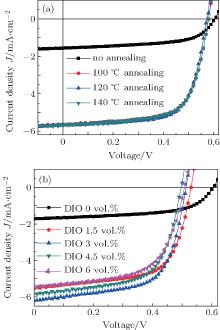
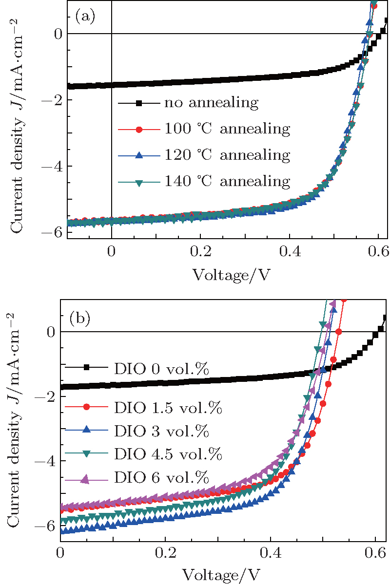
Devices with blends prepared using thermal annealing or solvent additive exhibit higher photocurrents (Jsc), higher fill factor (FF), and lower open circuit voltages (Voc) than cells with blends prepared without annealing or additive (Jsc = 1.72 mA/cm2, Voc = 0.61 V, FF= 57.47%). Due to the relatively large increase in the Jsc and FF compared to decrease in Voc, the blend prepared with 120 ° C annealing results in the highest device efficiency (Eeff = 2.24%), while the blend prepared with 3 vol.% DIO added exhibits a slightly smaller increase in device efficiency (Eeff = 2.02%). The significant differences in Jsc between the devices investigated here are attributed to improvements in the crystallinity of the P3HT phase that we discussed earlier. While higher crystallinity P3HT films have a reduced bandgap compared to a film with the lower crystallinity, [46, 47] leading to slight decrease in Voc; the Voc can be further limited by recombination and contact effects.[24] We attribute the differences of FF to the improved bulk transport properties and the efficiency of charge collection due to the ordered P3HT domains and better phase segregation in the devices.
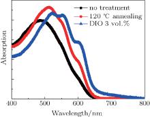
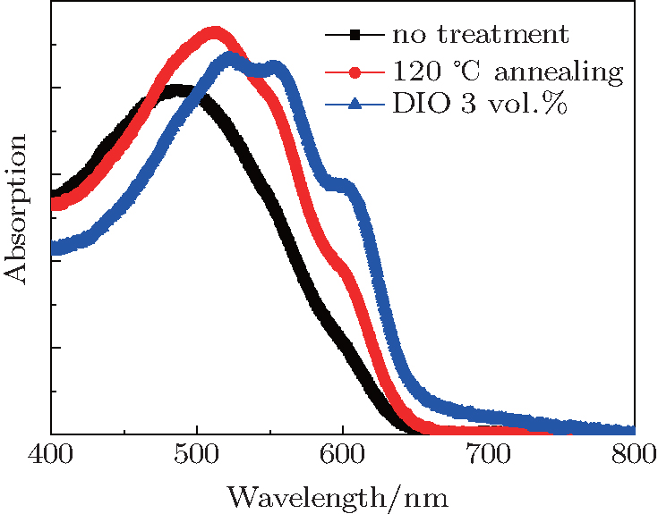
The absorption spectra in Fig. 9 show that blend films, either annealed or with DIO added, exhibit higher absorption than that of the untreated film, while the two blends have rather different modulations in the intensity and peak position of the main absorption peak near 520 nm corresponding to a π − π * transition. The DIO-added blend shows a significant red-shift compared to the pristine blend and the annealed blend. The increase of absorption at 600 nm is an indication of stronger intraplanar interaction within highly ordered P3HT[48] and appears to be more pronounced in the DIO-added blend, attributable to the interplanar stacking we detected using GIXRD.
A portion of this work is based on the data obtained at 1W1A, BSRF. The authors gratefully acknowledge the assistance of scientists of the Diffuse x-ray Scattering Station during the experiments.


 , Chen Yu