


Tuning the magnetic anisotropy of CoFeB grown on flexible substrates
[Zhang Haoa) , Li Yuan-Yuana) , Yang Mei-Yina) , Zhang Baoa) , Yang Guangb) , Wang Shou-Guo†b)  , Wang Kai-You‡
a) ]
, Wang Kai-You‡]
 |

 , Wang Kai-You‡
†Corresponding author. E-mail: sgwang@iphy.ac.cn
‡Corresponding author. E-mail: kywang@semi.ac.cn
*Project supported by the National Basic Research Program of China (Grant Nos. 2011CB922201 and 2015CB921401) and the National Natural Science Foundation of China (Grant Nos. 11174272, 11474272, 11274371, 51431009, and 61225021).
The magnetic properties of CoFeB thin films grown on flexible polyimide substrates were investigated using a magneto-optical Kerr effect magnetometer. In-plane uniaxial magnetic anisotropy was observed in the virgin state. The strain induced by bending the flexible substrate was applied on the sample to change the magnetic properties of CoFeB. The strain induced uniaxial magnetic anisotropy changed linearly with the deformation by about 8.41 × 1041 erg/cm3 at 1% of deformation. Our results prove the magnetic properties of CoFeB grown on flexible polyimide substrate can be tuned effectively by bending, which could be important for future flexible spintronics.
Magnetization orientation is widely used for information processing and storage applications.[1] For decades, interest to discover methods that could efficiently control the magnetization orientation has been rapidly growing. Since the strain and deformation can significantly affect the magnetic properties in materials, we can tune the strain applied on the sample to control the magnetic anisotropy and magnetic reversal. The approaches adopted to achieve this goal include using the strain induced by lattice mismatch with the substrate’ s epitaxial growth on substrates, [2, 3] bonding magnetic thin film to the piezoelectric materials, [4– 8] and growing thin films on top of the flexible substrates.[9– 13] Large deformation induced by bending the flexible substrate can effectively tune the magnetic properties. The flexible substrates normally are more rugged, lighter, portable, and less expensive to manufacture compared to their rigid substrate counterparts. Due to the advantages of the flexible substrates, flexible electronics, including flexible solar cell arrays, flexible organic light-emitting diode displays, etc., have attracted considerable interest in the past few decades. The ferromagnetic materials grown on the flexible substrates could be a new solution for future flexible spintronics. Thus it is important to investigate how magnetic properties are affected by the deformation of the flexible substrates. The ferromagnetic CoFeB exhibits perfect soft ferromagnetism[14] and possesses very high spin polarization[15] with a large tunneling magnetoresistance (TMR) in magnetic tunnel junctions, which can be used as building blocks of magnetoresistive random access memory (MRAM).[16] In the previous work, [13] CoFeB thin films were deposited on polyethylene terephthalate (PET) substrates and the remanence under different strains was studied. However, the low working temperature (below 120 ° C of PET limits its application in high temperature environments. Compared to other flexible substrates like PET, polyimide (PI) has greater thermal stability. High working temperature (about 300 ° C of PI substrates improves the thermal stability, which is important for the devices when processing at high temperature in integrated circuit applications. And for the mechanical performance, the Poisson’ s ratio of the PI substrate is about 0.35, [17] which is lower than that of the PET substrate (0.4). For the lower Poisson ratio in the PI substrate, the strain applied to the CoFeB thin films grown on the PI substrate can contribute more “ uniaxial” magnetic anisotropy than that on the PET substrate. Thus we expect to observe more obvious tuning effect in the CoFeB thin film grown on the PI substrate than that on the PET substrate.
In this work, we systematically investigate the tuning effect on the magnetic anisotropy of CoFeB by bending strain applied on the CoFeB/PI heterostructure. The bending of the CoFeB/PI heterostructure can introduce large extra uniaxial anisotropy to the CoFeB, which is about 8.41 × 10⁴ erg/cm3 at 1% of unit bending strain. Also, the introduced extra large magnetic anisotropy changes linearly with varying bending strain, which could be used for the next generation of magnetic strain sensor.
The 20 nm Co40Fe40B20 thin films were deposited onto a 125 μ m thick PI flexible substrate by dc magnetron sputtering. After deposition of 20 nm-thick Co40Fe40B20, a 5 nm thick tantalum layer was capped on the top to avoid oxidation. During the deposition process, the growth rate of CoFeB was kept at 0.0474 nm/s and the pressure was set at 0.07 Pa. The strain induced by bending the flexible PI substrate can be transferred to the CoFeB thin films (shown in Fig. 1). When a mechanically homogeneous sheet with a thickness d is bent to a cylinder with a radius R (perpendicularly to the axis of bending), its outside surface expands and its inside surface is compressed by the bending strains ε = d/2R and − d/2R, respectively. The bases with four different curved surfaces were fabricated to produce different compressive and tensile strains with ε = − 7.1 × 10− 3, − 5.1 × 10− 3, 5.1 × 10− 3, and 7.1 × 10− 3. The CoFeB thin films were fabricated into squares with edge length of l = 3 mm. Then the CoFeB samples were bonded to the bases with different ε to introduce varied bending strain on the sample. The magnetic properties of CoFeB were investigated by bending the PI substrates to different degrees of curvature. The stress applied on the CoFeB thin films can be calculated using

where ε is the bending strain, Ef is the Young’ s modulus, v is the Poisson ratio, and σ is the stress. This equation is Hooke’ s law to describe the strain– stress relationship in thin films. Consider the CoFeB thin films bonded to the flexible PI substrate and subjected to the tensile strain. The transverse compressive stress (σ y) of the film can be determined by the different transverse strains between CoFeB thin films and PI substrate due to the difference of their Poisson ratios, which can be calculated by

where vsubstrate and vCoFeB are the Poisson ratios of PI (0.35) and CoFeB (0.3), respectively.[13] For the CoFeB thin films adhered to the PI substrate, the strains applied on the CoFeB and the PI substrate are equal 

The ratio ∣ σ y/σ x∣ in the PI substrate is 0.045, which is much smaller than that in the PET substrate (∣ σ y/σ x ∣ = 0.091).[13] These analyses are also suitable for the situation of the compressive strain being applied on the sample. The results indicate that the strain applied on the CoFeB thin films grown on PI substrate can produce more uniaxial magnetic anisotropy than that in the case of CoFeB thin films on PET substrate. Thus the strain can more effectively tune the magnetic anisotropy of CoFeB in the CoFeB/PI heterostructure.
 | Fig. 1. Sketch of (a) tensile strain and (b) compressive strain applied on the CoFeB thin films grown on flexible PI substrate. |
The magnetization vectors of the thin film during magnetization reversal along different in-plane orientations were measured by using a magneto-optical Kerr effect magnetometer (MOKEM). The instrument model is NanoMOKE@3. In our longitudinal setup, the Kerr rotation angle is proportional to the magnitude of the magnetization component along the projection direction of the incident light in the plane.[8] The magnetization vectors thus can be used to determine the relative magnitude (M/MS) (where M is the magnetization component along the magnetic field direction and MS is the saturation magnetization) and direction of the magnetization. Thus, the hysteresis loops with the magnetic field along different in-plane orientations measured by the longitudinal Kerr effect can be used to investigate the magnetic anisotropy. All the measurements were carried out at room temperature and the frequency of the magnetic field was fixed at 0.5 Hz.
The crystal structure of the as-deposited CoFeB film was investigated by x-ray diffraction (XRD) with x-ray wavelength λ = 0.15418 nm. The XRD patterns of the CoFeB thin film and the PI flexible substrate are shown in Fig. 2. From the XRD pattern, we see that the peaks that appear below 40° belong to the PI substrate. These results demonstrate that most of the as-deposited CoFeB thin films herein are in the amorphous phase, yielding no apparent diffraction peak.
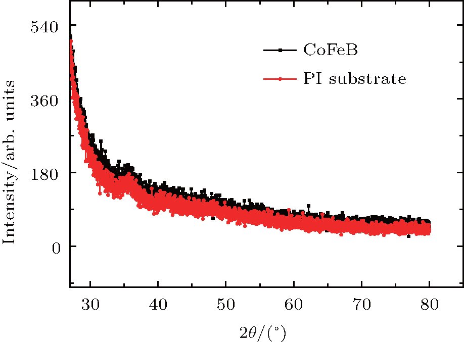 | Fig. 2. XRD patterns of CoFeB thin films and PI flexible substrate. |
In principle, the amorphous CoFeB thin film is expected to have in-plane magnetic isotropy. However, in-plane magnetic anisotropy was observed in the amorphous CoFeB thin film. Figure 3(a) shows the magnetic hysteresis loops of the CoFeB thin film in the virgin state with the external field applied along easy and hard axes. The hysteresis loop for the field applied along the easy axis is square with a MR/MS ratio of 0.99, while the hysteresis loop along the hard axis is sheared with a squareness of 0.07.
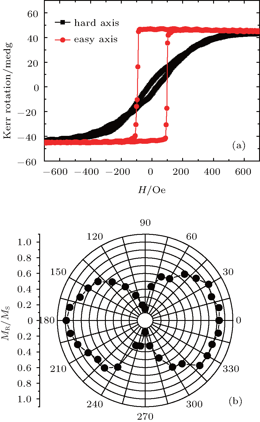 | Fig. 3. (a) Magnetic hysteresis loops of the CoFeB thin film in the virgin state with the external field applied along the in-plane hard and easy axes. (b) Remanence as a function of the field orientation φ for the CoFeB exhibits uniaxial symmetry about both the easy and the hard axes. The field orientation φ is defined as the angle between the external field and the easy axis. The easy axis is defined as φ = 0° and the hard axis is defined as φ = 90° . |
In order to better understand the magnetic anisotropy of the film, the magnetization reversal with external magnetic field applied in different in-plane orientations was investigated. The angular dependence of the remanent magnetization of the CoFeB thin films is illustrated in Fig. 3(b). It possesses a uniaxial symmetry about the easy and hard axes of the CoFeB thin films, which indicates a significant uniaxial magnetic anisotropy of the amorphous CoFeB grown on PI substrate. The field orientation φ is defined as the angle between the external magnetic field and the easy axis. The initial easy axis is defined as φ = 0° and the initial hard axis is defined as φ = 90° . The uniaxial anisotropy of the flexible CoFeB films may originate from the residual stress caused by the slightly inevitable deformation of the PI substrate.[10, 11, 13] The continuous film without strain requires 100 Oe to reach the saturated magnetization in the easy axis, while it needs 500 Oe to reach the saturated magnetization in the direction of the hard axis.
To understand the magnetic properties of the CoFeB films under different bending strains, we investigated the magnetization reversals of the films using MOKEM with magnetic field applied in the initial easy and hard axes (results are shown in Fig. 4), where the bending strain was applied along the initial easy axis direction (φ = 0° ).
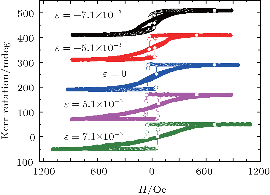 | Fig. 4. Magnetic hysteresis loops of the CoFeB thin films under different bending strains with magnetic field applied along the initial hard axis (solid dots) and easy axis (open circles). The bending strain was applied along the initial easy axis (φ = 0° ) from compressive to tensile (top to bottom shift by 120 mdeg) with ε = − 7.1 × 10− 3, − 5.1 × 10− 3, 0, 5.1 × 10− 3, and 7.1 × 10− 3, respectively. |
With the bending strain ε along the initial easy axis (φ = 0° ) varying from − 7.1 × 10− 3 to 7.1 × 10− 3, the hysteresis loops of the CoFeB thin films with external field along both the φ = 0° and 90° directions are shown in Fig. 4. The remanence of the hard axis in the CoFeB/PI system is changed from 0.26 to 0.02 with the bending strain varied from − 7.1 × 10− 3 to 7.1 × 10− 3, corresponding to about 93% variation of the remanent magnetization. The variation of the remanent magnetization (93%) is more than 3 times that observed in the CoFeB thin film grown on PET.[13] In contrast with the virgin state, the hysteresis loop along the easy axis becomes more and more squared and sharp with increasing tensile strain. At the same time, the saturation magnetic field increases with increasing tensile strain when the external magnetic field is in the direction of φ = 90° . The increase of the saturation magnetic field suggests that the tensile strain induced extra uniaxial magnetic energy has the same direction as the intrinsic uniaxial magnetic energy. However, with increasing compressive strain, the hysteresis loop along the easy axis becomes less and less squared. Also the saturation magnetic field decreases with increasing compressive strain with the field applied in the φ = 90° direction. The hysteresis loops are even comparable for the field applied in the φ = 0° direction and the φ = 90° direction under the compressive bending strain of − 7.1 × 10− 3. This indicates that the compressive strain introduces the sign for the extra uniaxial magnetic anisotropy that is opposite to that of the intrinsic uniaxial anisotropy of CoFeB.
For quantifying the overall magnetic energy of the continuous films with strain applied, the additional anisotropy therefore should be treated on equal footing with the intrinsic uniaxial anisotropy. For the square shape of the sample with edge length of 3 mm, the sample can be taken as a continuous film. Thus, the influence of the shape factor on the in-plane magnetic anisotropy can be neglected. We use the magnetic energy density in an applied field

where KU is the intrinsic uniaxial anisotropy constant, KB is the additional uniaxial anisotropy constant introduced by the bending strain, H is the external applied field, MS is the saturation magnetization, and θ is the angle between the magnetization and the initial easy axis. By varying the bending strain, the associated magnetic energy is also changed, thus we can control the shape of the hysteresis loop under different bending strains.
The strength of the total uniaxial magnetic anisotropy K(K = KB + KU) under different bending strains can be obtained using the relation K = HKMS/2, where HK is the magnetic anisotropic field. The saturation magnetization MS of CoFeB is about 1100 emu/cm3.[18] The magnetic anisotropic field can be determined by the hysteresis curves measured along the hard axis (φ = 90° ) where the magnetization coincides with the magnetization of the hysteresis loop along the easy axis.[10, 19, 20] The obtained uniaxial magnetic anisotropy K for the sample under different strains is shown in Fig. 5, where K is proportional to the bending strain applied on the CoFeB thin films grown on flexible substrate. Without bending strain applied on the sample, KU is about 2.86 × 10⁵ erg/cm3. When varying the bending strain from − 7.1 × 10− 3 to 7.1 × 10− 3, the overall uniaxial anisotropy K linearly increases from about 2.20 × 10⁵ erg/cm3 to 3.39 × 10⁵ erg/cm3 which is shown in the inset of Fig. 5. The induced extra uniaxial magnetic anisortropy linearly changes with the varying bending strain, which is about 8.41 × 10⁴ erg/cm3 with 1% of unit bending strain. The strain induced large uniaxial magnetic anisotropy could be used for the next generation magnetic strain sensor.
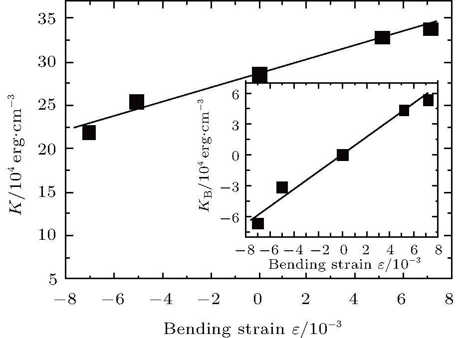 | Fig. 5. The overall uniaxial anisotropy constant K’ s dependence on the bending strain applied on the CoFeB thin films with φ = 0° , grown on flexible PI substrate. The inset shows the bending strain dependence of the additional uniaxial anisotropy KB induced by the bending strain. The lines are guides to the eye. |
In summary, the tuning effect of the continuous CoFeB thin films grown on flexible PI substrate through bending was investigated using a magneto-optical Kerr effect magnetometer (MOKEM). The bending strain can effectively tune the magnetic properties of CoFeB in the CoFeB/PI heterostructures. With bending along the initial magnetic easy axis direction, the tensile strain increased the total uniaxial anisotropy, while the compressive bending strain decreased this anisotropy. The extra uniaxial anisotropy changed linearly with varying strain, which was about 8.41 × 10⁴ erg/cm3 at 1% of deformation. The large change of the uniaxial magnetic anisotropy with deformation in CoFeB/PI could be important for future flexible spintronics, especially for the magnetic strain sensors with very high sensitivity.
| 1 |
|
| 2 |
|
| 3 |
|
| 4 |
|
| 5 |
|
| 6 |
|
| 7 |
|
| 8 |
|
| 9 |
|
| 10 |
|
| 11 |
|
| 12 |
|
| 13 |
|
| 14 |
|
| 15 |
|
| 16 |
|
| 17 |
|
| 18 |
|
| 19 |
|
| 20 |
|