Coherent and tunable radiation with power enhancement from surface plasmon polaritons
Cooperative Innovation Centre of THz Science, University of Electronic Science and Technology of China, Chengdu 610054, China
†Corresponding author. E-mail: triwoods.uestc@163.com
*Project supported by the National Basic Research Program of China (Grant No. 2014CB339801), the National Natural Science Foundation of China (Grant Nos. 61231005, 11305030, and 612111076), and the National High Technology Research and Development Program of China (Grant No. 2011AA010204).
1. IntroductionSurface plasmon polaritons (SPPs) are slow waves that are caused by the collective oscillations of the free electron gas in noble metals.[1, 2] They can be excited not only by plane waves with wave vector compensation, but also by perpendicularly or parallelly moving electron beams (e-beam).[3– 7] SPPs have become attractive research topics due to their interesting physics and important applications, such as enhanced radiation, [8– 10] enhanced optical transmission, [11] field imaging, [12] terahertz devices, [13] and biosensor.[14]
Recently, an attractive SPPs Cherenkov light radiation source (SPCLS) with a simple structure of a metal film with a dielectric medium loading was presented in Ref. [8]. In SPCLS, SPPs on the metal film are at first excited by a parallelly moving e-beam. They are then transformed into radiation waves with strong power enhancement when the Cherenkov radiation (CR) condition is satisfied in the dielectric medium. SPCLS provides a promising way to obtain a coherent and tunable radiation source within a wide frequency range or a sensitive particle detector.[15] SPCLS can also be excited by a perpendicularly moving e-beam. However, the radiation waves in this case are incoherent and untunable because all of the SPPs are excited by the perpendicularly moving e-beam.[7] In this paper, we aim to look for stronger radiation power enhancement and extend the radiation frequency tuning band by analyzing the physical process of the radiation transformation in parallelly excited SPCLS and investigating their radiation properties.
This paper is organized as follows. The physical process of the radiation transformation in SPCLS is analyzed in Section 2. The dependencies of the radiation power enhancement on the e-beam energy and the film thickness are presented in Section 3. Section 4 analyses the radiation frequency. Section 5 gives the summary.
2. Radiation transformation in SPCLSA schematic of SPCLS is shown in Fig. 1(a), in which a metal film is supported by a dielectric medium and an e-beam is uniformly moving parallel to the metal film surface. Many materials, such as metals Ag, Au, Al and dielectric media Bi3Ge4O12 (BGO), SiC, SiO2, ZnSe, MgO-TiO2, can be used in SPCLS.[8] To simplify the analysis, in this paper the dielectric medium is BGO, [16] and the metal film is Ag with its relative permittivity described by the modified Drude model  , where ε ∞ = 5.3, ω p = 1.39 × 10¹⁶ rad/s, and γ = 3.21 × 10¹³ Hz.[17– 20] Making use of the Maxwell’ s equations and the boundary conditions, we can obtain the dispersion equation of SPCLS

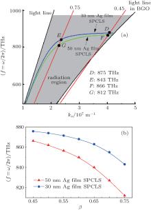
where  , k0 = ω /c, c is the velocity of light in a vacuum, and ε Ag and ε 3 are the relative permittivities of the Ag film and BGO, respectively. The dispersion curve is drawn in Fig. 1(b).
For the thin metal film supported by a dielectric medium, there are symmetrical and asymmetrical modes of SPPs, depending on the distribution of field Ez on the perpendicular direction of the film (Y direction in this structure).[1] As shown in Fig. 1(b), the dispersion curves of both modes are always below the light line in vacuum because SPPs are slow waves and none of them can be transformed into radiation waves in the vacuum. However, the wavevector of part of the asymmetrical mode can be smaller than that of light in the dielectric medium. Then, as shown in Fig. 1(b), part of its dispersion curve locates in the radiation region between the light lines in a vacuum and those in the dielectric medium. SPPs located in this region can be transformed into radiation waves. When SPCLS is excited by a parallel e-beam, only the SPPs corresponding to the working point, which is the cross point of the e-beam line and the dispersion curve, can be excited.[7] This means that if the working point lies in the radiation region, then coherent radiation waves can be obtained in the dielectric medium.
For example, in the case of e-beam energy β = 0.6 (the e-beam energy is described by β , where β = u0/c and u0 is the velocity of the moving e-beam), the corresponding working point A lies in the radiation region, and then the excited SPPs with operating frequency 850 THz can be transformed into radiation waves, whose contour map is shown in Fig. 2(a). It is illustrated in this figure that the excited SPPs are confined to the vacuum/film interface and they decay exponentially away from this interface in the vacuum. In the film, the excited SPPs decay rapidly in the Y direction until they are transformed into radiation waves in the medium. This indicates that the SPPs are excited firstly on the vacuum/film interface by the parallelly moving e-beam, and they then penetrate though the metal film with attenuation along the Y direction. Finally, they are transformed into radiation waves in the dielectric medium with a radiation angle that is determined by the e-beam energy together with the permittivity of the dielectric medium, as shown by the following equation:

Accordingly, the radiation angle can be changed by adjusting the e-beam energy, and the maximum radiation angle θ max is determined by the dielectric medium.
In the case of β = 0.3, the corresponding working points B and C lie outside of the radiation region, the excited SPPs with operating frequencies 607 THz and 874 THz cannot be transformed into radiation waves, whose contour maps are show in Figs. 2(b) and 2(c), respectively. It can be seen that the fields of the excited SPPs are both confined to the film surface and decay exponentially to zero along the Y direction. The skin depths of the SPPs fields in vacuum and dielectric are  and
and  , respectively, where
  and
and  are given in Eq. (1).
3. Radiation power enhancement in SPCLSIn the case that an e-beam is moving parallel to a dielectric medium without a metal film, CR can be generated in the medium when the e-beam energy is larger than the CR threshold.[8, 21, 22] When there is a metal film located above the dielectric medium (SPCLS), due to the excited SPPs in the film, the radiation power (PSPCLS) can be enhanced compared to that without the metal film (PCR). This enhancement can then be obtained in the frequency domain by η (ω ) = PSPCLS/PCR.
3.1. Power intensity ratio and SPPs’ energy lossTo analyze the radiation power enhancement in SPCLS, we first study the power intensity ratios on the vacuum/film interface of the excited SPPs and the incident waves from e-beam at the SPPs’ operating frequency. Making use of the nonhomogeneous Helmholtz equation and the boundary conditions, we can obtain the electric field of the excited SPPs on the vacuum/film interface of SPCLS:

where  , q is the charge density of the e-beam,
  and kz = ω /u0.
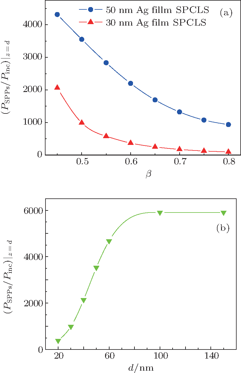
Based on the relationship  , the power intensity PSPPs| z= d (d is the film thickness as shown in Fig. 1(a)) of the excited SPPs on the vacuum/film interface can be obtained, as can that of the incident waves Pinc| z= d.[23] The power intensity ratios of the excited SPPs and the incident waves at the SPPs’ operating frequency for varying e-beam energy in SPCLS with 30 nm and 50 nm Ag films are shown in Fig. 3(a). In this paper, we focus on the excited SPPs that can be transformed into radiation waves, and then the e-beam energy should be larger than the CR threshold β CR
 It can be seen that this ratio decreases with the increasing e-beam energy, and the largest value is obtained at the e-beam energy near to β CR in BGO. For example, excited by an e-beam of β = 0.45 (61 keV), the SPPs obtain the power intensity ratio 2063 in SPCLS with 30 nm Ag film and 4314 with 50 nm Ag film.
The dependence of this ratio on the film thickness for fixed e-beam energy β = 0.6 is shown in Fig. 3(b). It can be seen that the power intensity ratio at first increases to a peak value with the increasing film thickness, it then saturates. This happens because when the film is thick enough, thicker than 80 nm as shown in Fig. 3(b), the excitation of SPPs on the film can be regarded as that on a semi-infinite metal.[7]
In SPCLS, the excited SPPs on the vacuum/film interface penetrate though the film with rapid attenuation along the Y direction. They are then transformed into radiation waves on the film/medium interface. Accordingly, the energy loss of the excited SPPs in the film should also be studied to analyze the radiation power enhancement in SPCLS. For the Ag film in SPCLS with fixed thickness, the SPPs’ energy loss decreases with the increasing e-beam energy. This happens because the propagation constant kz (kz = ω /u0) of the excited SPPs in Eq. (2) decreases with the increasing e-beam energy. The decreasing kz leads the decreasing wave number  along the Y direction. This leads to the increase of the skin depth of the excited SPPs field, which is inversely proportional to the penetration energy loss for the Ag film with fixed thickness. On the other hand, for the fixed e-beam energy, the energy loss increases with the increasing film thickness. This happens because the increasing film thickness gives rise to the increasing distance of attenuation of the excited SPPs.
3.2. Radiation power enhancement in SPCLSBased on the physical process of the radiation transformation in SPCLS, the radiation power enhancement is determined by the power intensity ratio of the excited SPPs and the incident waves from e-beam, together with the SPPs’ penetration energy loss in the film. We now use the results given above to analyze the dependencies of the radiation power enhancement on the e-beam energy and parameters of the film.
The radiation field in the dielectric medium can be obtained as

where Bi and kc are the same as those given in Eq. (3). When the e-beam energy is larger than β CR in the dielectric medium,  in Eq. (4) is imaginary, and then
  becomes a radiation field. Based on the relationship
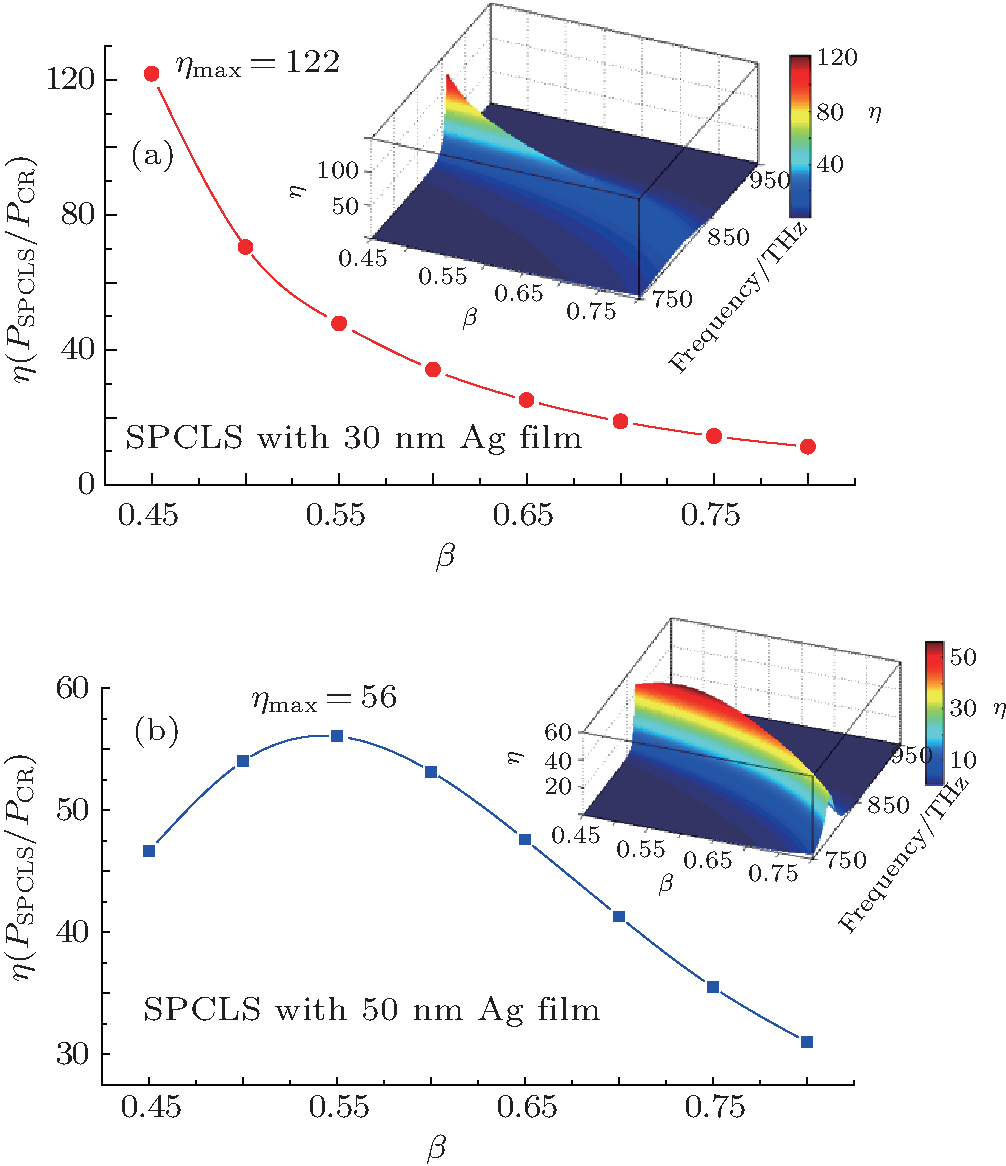
  , the radiation power PSPCLS can be calculated, and then the radiation power enhancements η (ω ) can be obtained, which are illustrated in Figs. 4(a) and 4(b).
As shown in Fig. 4(a), for SPCLS with 30 nm Ag film, the radiation power enhancement η decreases rapidly with the increasing e-beam energy. It obtains the maximum value η max = 122 when the e-beam energy (β = 0.45) is near to β CR in BGO. This happens because the penetration energy loss of the excited SPPs is very weak for the 30 nm Ag film, and the power intensity of the excited SPPs dominates the radiation power enhancement in SPCLS. The power intensity of the excited SPPs decreases with the increasing e-beam energy, and this causes the decreasing enhancement in SPCLS.
However, the dependence of this enhancement on the e-beam energy exhibits a different tendency for SPCLS with 50 nm Ag film. As shown in Fig. 4(b), the enhancement at first grows with the increasing e-beam energy, it then decreases. The maximum value η max is 56 at e-beam energy β = 0.54 (96 keV). This happens because the penetration energy loss of the SPPs becomes remarkable for the 50 nm Ag film, and then the enhancement is determined by the power intensity of the excited SPPs together with their penetration energy loss. When the e-beam energy is near to β CR, the energy loss dominates this enhancement in SPCLS. The energy loss decreases with the increasing e-beam energy, which causes the increasing enhancement. With a further increase of the e-beam energy, the decreasing power intensity of the excited SPPs determines the enhancement in SPCLS, which causes the decreasing enhancement. It can be clearly seen from the insets of Figs. 4(a) and 4(b) that for radiation waves in SPCLS only the frequency component at the operating frequency of the excited SPPs is dramatically enhanced.
The dependence of the maximum radiation power enhancement η max (at the optimized e-beam energies) in SPCLS on varying Ag film thickness is shown in Fig. 5. It can be seen that the maximum enhancement increases with the increasing film thickness from 10 nm to 30 nm and then decreases, and η max obtains the largest value when the Ag film thickness is between 20 nm and 30 nm. When the film is 10 nm or 20 nm thick, the power intensity of the excited SPPs is very small, which in turn leads to a small η max. With the increase of the film thickness, not only the intensity of the excited SPPs but also the energy loss in the film increases. When the film thickness is larger than 30 nm, the large energy loss also leads to a small η max. Accordingly, the largest value of η max can be obtained by optimizing the thickness of the Ag film in SPCLS together with the e-beam energy.
4. The radiation frequency in SPCLSBecause the radiation frequency of SPCLS is determined by the operating frequency of the excited SPPs, it can be tuned by adjusting the e-beam energy. The dispersion curves of SPCLS with 30 nm Ag film and 50 nm Ag film in the radiation region are shown in Fig. 6(a). It can be seen that, for SPCLS with 30 nm Ag film, the radiation frequency is 875 THz for β = 0.45, and 843 THz for β = 0.75. Whereas for SPCLS with 50 nm Ag film, it is 866 THz for β = 0.45, and 812 THz for β = 0.75. Accordingly, in the same e-beam energy variation range, a wider radiation frequency tuning band can be obtained in SPCLS with 50 nm Ag film against that with 30 nm Ag film. As shown in Fig. 6(b), the tuning band of radiation frequency of SPCLS with 50 nm Ag film reaches up to 6.5% (β from 0.45 to 0.75), whereas that of SPCLS with 30 nm Ag film is 3.6% (β from 0.45 to 0.75).
Since the dispersion relation of asymmetrical mode of SPPs is mainly determined by the SPPs on the vacuum/film interface, the permittivity of the dielectric medium almost makes no differences to the radiation frequency of SPCLS when the radiation is generated. The radiation frequency then remains almost the same with the increasing permittivity of the dielectric medium, but the radiation angle will increase with the increasing permittivity.
5. SummaryThe detailed analyses and numerical calculation given in this paper show that, in SPCLS, SPPs are first excited by the parallel moving e-beam on the vacuum/film interface and then penetrate though the metal film until they are transformed into enhanced and coherent radiation waves in the dielectric medium. Strong radiation power enhancement and wide radiation frequency tuning band in SPCLS can be obtained by optimizing the e-beam energy and the film thickness. For SPCLS with Ag film and BGO medium, the largest radiation power enhancement reaches up to 122 times and the radiation frequency tuning band reaches up to 6.5%. The results obtained in this paper will facilitate the practical applications of light radiation source and the sensitive particle detector of SPCLS.


 , Zhong Ren-Bin, Hu Min, Chen Xiao-Xing, Zhang Ping, Zhao Tao, Liu Sheng-Gang]