Yan Ling-Hao, Wu Rong-Ting, Bao De-Liang, Ren Jun-Hai, Zhang Yan-Fang, Zhang Hai-Gang, Huang Li, Wang Ye-Liang, Du Shi-Xuan†, Huan Qing‡, Gao Hong-Jun. Adsorption behavior of Fe atoms on a naphthalocyanine monolayer on Ag(111) surface* . Chinese Physics B, 24(7): 076802
Permissions
Adsorption behavior of Fe atoms on a naphthalocyanine monolayer on Ag(111) surface*
Yan Ling-Haoa), Wu Rong-Tinga), Bao De-Liangb), Ren Jun-Haia), Zhang Yan-Fanga), Zhang Hai-Gangc), Huang Lia), Wang Ye-Lianga),b), Du Shi-Xuan†a),b), Huan Qing‡a),b), Gao Hong-Juna),b)
Beijing National Laboratory for Condensed Matter Physics, Institute of Physics, Chinese Academy of Sciences, Beijing 100190, China
University of Chinese Academy of Sciences, Beijing 100049, China
Center for Nanoscale Materials, Argonne National Laboratory, Chicago, IL 60439, USA
*Project supported by the National Natural Science Foundation of China (Grant Nos. 61390501, 51325204, and 11204361), the National Basic Research Program of China (Grant Nos. 2011CB808401 and 2011CB921702), the National Key Scientific Instrument and Equipment Development Project of China (Grant No. 2013YQ1203451), the National Supercomputing Center in Tianjin, China, and the Chinese Academy of Sciences.
Abstract
Adsorption behavior of Fe atoms on a metal-free naphthalocyanine (H2Nc) monolayer on Ag(111) surface at room temperature has been investigated using scanning tunneling microscopy combined with density functional theory (DFT) based calculations. We found that the Fe atoms were adsorbed on the centers of H2Nc molecules and formed Fe–H2Nc complexes at low coverage. DFT calculations show that Fe sited in the center of the molecule is the most stable configuration, in good agreement with the experimental observations. After an Fe–H2Nc complex monolayer was formed, the extra Fe atoms self-assembled to Fe clusters of uniform size and adsorbed dispersively at the interstitial positions of Fe–H2Nc complex monolayer. Therefore, the H2Nc monolayer grown on Ag(111) could be a good template to grow dispersed magnetic metal atoms and clusters at room temperature for further investigation of their magnetism-related properties.
PACS:
68.37.Ef; 68.35.bm; 68.35.Fx; 68.35.Md
Keyword:
naphthalocyanine; Fe atoms; Ag(111) surface; adsorption behavior
The self-organized growth and self-assembled behavior of atomic and molecular nanostructures on metal surfaces are of great interest in surface science and molecular electronics.[1– 3] Naphthalocyanines (Ncs), which consist of a planar phthalocyanines (Pcs) framework with additional benzene rings attached to the four benzopyrrole units, show properties similar to Pcs but with extended delocalized π electrons. These extended delocalized π electrons result in optical and electronic properties that differ from those of Pcs.[4– 6] As the light absorption of Ncs matches better with the solar spectrum than Pcs, Ncs are considered to be ideal candidates for optical applications.[7– 10]
Metal-Pc molecules have been studied intensively, both for fundamental physics[11, 12] and for applications in electronics, optics, rotors, and even spin-based information technology.[13– 15] The growth behavior from submonolayer to bilayer has also been studied.[16– 23] Metal-free naphthalocyanine (H2Nc) has been investigated on different substrates.[24– 31] On the other hand, for Ncs combined with metal atoms, Gopakumar et al.[32, 33] reported the differences between tinnaphthalocyanine (SnNc) and H2Nc on highly oriented pyrolytic graphite. Their results show that SnNc is nonplanar in geometry and has a smaller HOMO– LUMO gap than H2Nc, due to the metal ion. However, few studies of magnetic metal-Nc complexes have been reported.
In this paper, we report on the adsorption behavior of Fe atoms with different coverage on a H2Nc monolayer on Ag(111) surface at room temperature. After depositing Fe atoms onto a H2Nc monolayer, we first observed the formation of Fe– H2Nc complexes by scanning tunneling microscopy (STM). The Fe atoms showed a monodispersed distribution in the H2Nc monolayer. With gradually increasing coverage of Fe atoms, the H2Nc monolayer transformed into an Fe– H2Nc complex monolayer. Moreover, after this complex monolayer was formed, the extra Fe atoms self-assembled into dispersed Fe clusters on certain sites. As the magnetic clusters are of fundamental interest with regard to spin and other magnetic properties, this method provides a way to control the size and distribution of magnetic clusters, and further, to characterize the features of magnetic atoms or clusters.
2. Methods
2.1. Experimental techniques
The experiments were carried out in a home-made UHV-STM system with a base pressure better than 2 × 10− 10 mbar. The substrate was Ag(111) with a purity of 99.999% (purchased from MaTecK GmbH), which was polished with an orientation better than 0.1° with respect to the nominal orientation. The Ag(111) surface was cleaned by repeated cycles of Ne sputtering and subsequent annealing at 770 K. H2Nc molecules (purchased from Sigma– Aldrich, 95% purity) were purified in vacuum by heating to 580 K for 100 h followed by heating to 610 K for 3 h. The H2Nc molecules were deposited at 610 K with a home-made K-cell evaporator onto the Ag(111) substrate at room temperature and subsequently annealed at 400 K to make a perfect monolayer of H2Nc. A home-made e-beam evaporator was used to deposit Fe atoms onto the sample held at room temperature. The evaporant was an Fe rod with a diameter of 3 mm and a purity of 99.99% (purchased from ESPI metals). The STM data were processed with WSxM software.[34] The voltages were applied to the samples, and the images were recorded in constant-current mode. Electrochemically etched tungsten tips were used for STM scanning.
2.2. Computational methods
First-principles calculations based on density functional theory (DFT) were performed in an all-electron plane-wave formulation with the projector augmented wave method (PAW) as implemented in the Vienna ab initio simulation package (VASP) code.[35, 36] The Perdew– Burke– Ernzernhof (PBE) flavor of the generalized gradient approximation (GGA) was used.[37] The H2Nc/Ag(111) supercell included three layers of Ag(111) with one H2Nc molecule adsorbed on one side and a vacuum layer of 25 Å . During calculations, the bottom layer of silver atoms was fixed, while the upper two layers of silver atoms and the H2Nc molecule were fully relaxed until the atomic forces were lower than 0.02 eV/Å . The Brillouin zone was sampled with only the Γ -point in all calculations. The cutoff energy for the plane waves was 400 eV. Van der Waals forces were considered by using Grimme’ s empirical correction and the standard value for each element in DFT+ D/PBE calculations.[38– 40] The adsorption energy for an Fe atom on H2Nc/Ag(111) system was defined as
3. Results and discussion
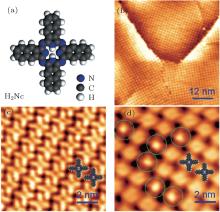
In order to get an intact monolayer of H2Nc, we first deposited slightly more than a monolayer coverage of H2Nc on Ag(111). In this state, the STM scanning at room temperature could not get clear images of the sample as there were extra H2Nc molecules diffusing fast on the first layer of H2Nc, which made the tip state very unstable. Then we annealed the sample at 400 K to remove the extra molecules from the first layer of H2Nc, and a perfect H2Nc monolayer was obtained. Figure 1(a) shows the structural model of H2Nc. Figure 1(b) is a large scale STM image which shows a clean self-assembled monolayer of H2Nc on Ag(111). In Fig. 1(b), the monolayer is formed by bright spots and the size of each spot is about 2 nm, which is comparable with the size of a H2Nc molecule. Therefore, each bright spot corresponds to one H2Nc molecule. The high-resolution STM image (Fig. 1(c)) shows that each H2Nc molecule has a clear cross-like shape with a dark center representing the inner cavity.
Fig. 1. Molecular model of H2Nc and STM images of H2Nc/Ag(111) before and after Fe deposition. (a) Model of H2Nc. (b) Large area STM image of H2Nc monolayer on Ag(111); each bright spot represents a H2Nc molecule. (c) High resolution STM image of H2Nc monolayer on Ag(111); H2Nc shows a cross-like shape. Two molecular models are superimposed on the image. (d) STM image of H2Nc monolayer after deposition of Fe atoms of 10% coverage; the green circles highlight the positions of specific Fe– H2Nc complexes. The scanning parameters of the STM images were − 2.0 V, 0.1 nA in panel (b), − 2.0 V, 0.1 nA in panel (c) and − 1.0 V, 0.1 nA in panel (d).
After depositing a small amount of Fe atoms onto the H2Nc monolayer, we found that some of the H2Nc molecules changed to an obviously different appearance with a small bright spot sitting on each of their centers, as shown in Fig. 1(d), marked with green circles. This suggests that Fe atoms adsorb at these molecular centers to form Fe– H2Nc complexes. Most likely, there are chemical bonds between the Fe atom and H2Nc, similar with the situation when Fe atoms were deposited onto metal-free phthalocyanines (H2Pc) monolayer.[41] Note that the introduction of Fe atoms does not change the molecular configurations. Both the H2Nc and Fe– H2Nc complex are sitting flatly on the surface, and they are able to coexist without affecting the conformations.
When the coverage of Fe atoms was very low (about 10%), all the Fe atoms seemed to be monodispersed, as shown in Fig. 1(d). When we increased the coverage of Fe atoms to approximately 55%, they still adsorbed at molecular centers. Here we define 100% coverage as the coverage when all the molecular centers are filled by Fe atoms. Figure 2(a) shows that two kinds of molecules were present on the surface at the same time, which are illustrated as two different models shown in Fig. 2(b). Both kinds of molecules lie flat on the surface and show symmetric cross-like features. Compared to H2Nc molecules with dark centers, Fe– H2Nc complexes show bright centers, representing the Fe atoms adsorbed on the centers of H2Nc molecules. When we further increased Fe coverage, all the centers of H2Nc molecules were occupied by Fe atoms, that is, a monolayer of Fe– H2Nc complex was formed (Fig. 2(c)). Considering the symmetry of the molecule and the substrate, we found H2Nc molecules can form six different domains on Ag(111).[31] The Fe– H2Nc complex can be found in all the six domains without priority.
Fig. 2. Molecular models and STM images of H2Nc with Fe deposition. (a) STM image (− 1.0 V, 0.1 nA) of 55% coverage of Fe atoms on H2Nc monolayer. (b) Models of H2Nc and Fe– H2Nc in panel (a). (c) STM image (− 1.0 V, 0.1 nA) of 100% coverage of Fe atoms on H2Nc monolayer. The dark centers of H2Nc molecules represent the inner cavities, whereas the bright centers of Fe– H2Nc complexes show that the Fe atoms are adsorbed on the centers of H2Nc molecules.
By increasing the coverage of Fe atoms step-by-step, more details about the adsorption process were revealed. First, at low Fe coverage, all the Fe atoms came onto the centers of H2Nc molecules. In the experiments, single Fe atoms were found neither on the lobes of a H2Nc molecule nor at other places between the H2Nc molecules. This implies that these sites are not the most stable sites for a single Fe atom at room temperature. When a single Fe atom is deposited onto the surface at room temperature, it will diffuse until it meets the center of an H2Nc molecule, where stable adsorption can happen. Therefore, the Fe atoms were monodispersed when the deposited atoms were limited. After a certain number of Fe– H2Nc complexes had been formed at the surface, a newly arrived Fe atom could not find a stable adsorption site nearby if its landing site was surrounded by Fe– H2Nc complexes. Thus, such an Fe atom had to diffuse to other place until it met an H2Nc molecule and then came onto the center of this molecule and formed a new Fe– H2Nc complex.
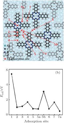
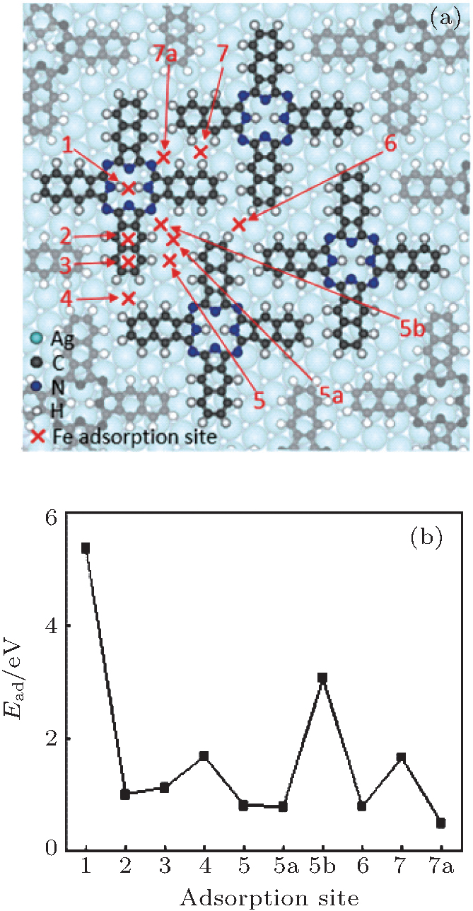
This process was further confirmed by our DFT calculations. We first relaxed different configurations and obtained the most stable one (Fig. 3(a)) for H2Nc molecules on Ag(111). Using this configuration as a template, several adsorption sites (Fig. 3(a)) were selected for a single Fe atom. As shown in Fig. 3(b), the adsorption energy for site 1 is obviously the highest of all. This means that the most stable adsorption site for an Fe atom adsorbed on H2Nc monolayer is site 1, which is the center of an H2Nc molecule. Therefore, when Fe atoms meet the H2Nc/Ag(111) surface, they will most likely be accommodated on site 1 and stay there. This result is in good agreement with the experimental observation. Until all sites 1 are fully occupied on the H2Nc/Ag(111) surface, the Fe atoms will look for other adsorption sites.
Fig. 3. Model of possible adsorption sites and adsorption energies of Fe on H2Nc/Ag(111). (a) Possible adsorption sites of Fe on H2Nc/Ag(111). (b) Calculated adsorption energies for Fe atoms adsorbed on respective sites shown in panel (a).
In addition, since Fe atoms were put onto a close-packed H2Nc monolayer, there might not be enough space for them to move under the molecules and interact with the Ag substrate. Instead, all the diffusion processes must be carried out at the monolayer’ s surface where Fe atoms behaved as hopping adatoms. A similar process has been observed in the tetraphenylporphyrin molecules’ metalation, in which the Fe atoms were hopping adatoms, as demonstrated by x-ray photoelectron spectroscopy (XPS) and near edge x-ray absorption fine structure spectroscopy (NEXAFS) results.[42]
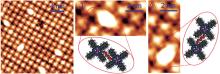
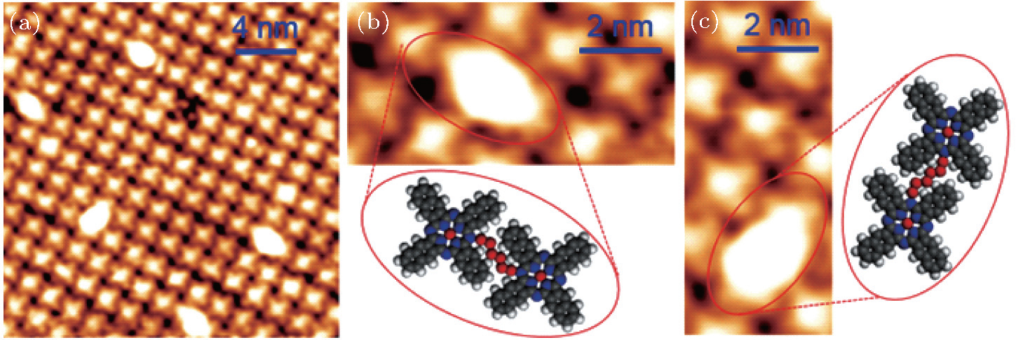
After all the H2Nc molecules were changed to Fe– H2Nc complexes, we deposited more Fe atoms onto the surface. Instead of finding more single atoms on other metastable adsorption sites, we found Fe clusters of uniform size located dispersively at the interstitial positions of the Fe– H2Nc complex monolayer, as shown in Figs. 4(a)– 4(c). More specifically, there were two kinds of orientations for Fe clusters, as shown in Figs. 4(b) and 4(c). These results reveal that after an Fe– H2Nc complex monolayer is formed, there is no stable adsorption site for a single Fe atom. Fe atoms prefer to form clusters on sites between two adjacent Fe– H2Nc complexes.
Fig. 4. Models and STM images of Fe clusters on H2Nc/Ag(111) after a full saturation of Fe atoms on the center of H2Nc molecules. (a) STM image of several Fe clusters on Fe– H2Nc complex monolayer on Ag(111). Fe clusters located between two Fe– H2Nc complexes. The sizes of the Fe clusters are identical. (b) and (c) STM images and schematic models of two Fe clusters with different orientations.
The size of the Fe clusters was apparently affected by the space between Fe– H2Nc complexes. The Fe clusters seemed to be of identical size. Thus it is reasonable to expect that ordered arrays of Fe clusters can be made by carefully tuning the experimental parameters. There are versatile properties in magnetic metal clusters such as Kondo effect, [43] magnetic anisotropy[44] and spin coupling.[45] Moreover, the molecular monolayer could act as a buffer layer to decouple the interaction between the metal clusters and the substrate, which will be helpful to study the intrinsic properties of magnetic atoms.[46, 47] Metal clusters of critical size are not stable on solid substrates at room temperature. They usually nucleate to big clusters or islands.[44, 48, 49] Our experiments show that Fe– H2Nc/Ag(111) is an ideal substrate to grow dispersed Fe clusters of uniform size, even at room temperature.
4. Conclusion
We studied the adsorption behavior of Fe atoms on a H2Nc monolayer on Ag(111) surface at room temperature. STM images and DFT calculations show that the centers of H2Nc molecules are the only stable adsorption sites for Fe atoms, resulting in Fe– H2Nc complexes. With increasing coverage of Fe atoms, every H2Nc was filled by an Fe atom in its cavity center and the H2Nc monolayer was changed into an Fe– H2Nc complex monolayer. After further depositing Fe, the extra Fe atoms self-assembled into Fe clusters located between adjacent Fe– H2Nc complexes. This method shows obvious advantages to control the size and distribution of metal clusters. Our work provides a good platform for further investigation of the intrinsic properties of monodispersed single atoms or clusters made of magnetic atoms.
Acknowledgments
The authors thank Werner A. Hofer in Newcastle University, Min Ouyang in University of Maryland and Sokrate Pantelides in Vanderbilt University for fruitful discussion.
GaoL, JiW, HuY B, ChengZ H, DengZ T, LiuQ, JiangN, LinX, GuoW, DuS X, HoferW A, XieX C and GaoH J2007Phys. Rev. Lett. 99106402DOI:10.1103/PhysRevLett.99.106402[Cited within:1]
12
LiuL, YangK, JiangY, SongB, XiaoW, ShiruS, DuS, OuyangM, HoferW A, Castro NetoA H and GaoH J2015Phys. Rev. Lett. 114126601DOI:10.1103/PhysRevLett.114.126601[Cited within:1]
WarnerM, DinS, TupitsynI S, MorleyG W, StonehamA M, GardenerJ A, WuZ, FisherA J, HeutzS, KayC W M and AeppliG2013Nature503504DOI:10.1038/nature12597[Cited within:1]
15
GaoL, LiuQ, ZhangY Y, JiangN, ZhangH G, ChengZ H, QiuW F, DuS X, LiuY Q, HoferW A and GaoH J2008Phys. Rev. Lett. 101197209DOI:10.1103/PhysRevLett.101.197209[Cited within:1]
... 3] Naphthalocyanines (Ncs), which consist of a planar phthalocyanines (Pcs) framework with additional benzene rings attached to the four benzopyrrole units, show properties similar to Pcs but with extended delocalized #cod#x03C0 ...
1
2009
0.0
0.0
... [4#cod#x2013 ...
1
1993
0.0
0.0
1
1998
0.0
0.0
... 6] As the light absorption of Ncs matches better with the solar spectrum than Pcs, Ncs are considered to be ideal candidates for optical applications ...
1
2004
0.0
0.0
... [7#cod#x2013 ...
1
2012
0.0
0.0
1
2013
0.0
0.0
1
2012
0.0
0.0
... 10] ...
1
2007
0.0
0.0
... Metal-Pc molecules have been studied intensively, both for fundamental physics[11,12] and for applications in electronics, optics, rotors, and even spin-based information technology ...
1
2015
0.0
0.0
... Metal-Pc molecules have been studied intensively, both for fundamental physics[11,12] and for applications in electronics, optics, rotors, and even spin-based information technology ...
1
2013
0.0
0.0
... [13#cod#x2013 ...
1
2013
0.0
0.0
1
2008
0.0
0.0
... 15] The growth behavior from submonolayer to bilayer has also been studied ...
1
1996
0.0
0.0
... [16#cod#x2013 ...
1
1997
0.0
0.0
1
2002
0.0
0.0
1
2007
0.0
0.0
1
2007
0.0
0.0
1
2011
0.0
0.0
1
2011
0.0
0.0
1
2012
0.0
0.0
... 23] Metal-free naphthalocyanine (H2Nc) has been investigated on different substrates ...
1
2007
0.0
0.0
... [24#cod#x2013 ...
1
2011
0.0
0.0
1
2007
0.0
0.0
1
2011
0.0
0.0
1
2012
0.0
0.0
1
2014
0.0
0.0
1
2014
0.0
0.0
2
2015
0.0
0.0
... 31] On the other hand, for Ncs combined with metal atoms, Gopakumar et al ...
... [31] The Fe#cod#x2013 ...
1
2006
0.0
0.0
... [32,33] reported the differences between tinnaphthalocyanine (SnNc) and H2Nc on highly oriented pyrolytic graphite ...
1
2006
0.0
0.0
... [32,33] reported the differences between tinnaphthalocyanine (SnNc) and H2Nc on highly oriented pyrolytic graphite ...
1
2007
0.0
0.0
... [34] The voltages were applied to the samples, and the images were recorded in constant-current mode ...
1
1996
0.0
0.0
... [35,36] The Perdew#cod#x2013 ...
1
1993
0.0
0.0
... [35,36] The Perdew#cod#x2013 ...
1
1992
0.0
0.0
... [37] The H2Nc/Ag(111) supercell included three layers of Ag(111) with one H2Nc molecule adsorbed on one side and a vacuum layer of 25#cod#x00A0 ...
1
2006
0.0
0.0
... [38#cod#x2013 ...
1
2010
0.0
0.0
1
2010
0.0
0.0
... 40] The adsorption energy for an Fe atom on H2Nc/Ag(111) system was defined as ...
1
2008
0.0
0.0
... [41] Note that the introduction of Fe atoms does not change the molecular configurations ...
1
2011
0.0
0.0
... [42] ...
1
2000
0.0
0.0
... There are versatile properties in magnetic metal clusters such as Kondo effect,[43] magnetic anisotropy[44] and spin coupling ...
2
2003
0.0
0.0
... There are versatile properties in magnetic metal clusters such as Kondo effect,[43] magnetic anisotropy[44] and spin coupling ...
... [44,48,49] Our experiments show that Fe#cod#x2013 ...
1
2006
0.0
0.0
... [45] Moreover, the molecular monolayer could act as a buffer layer to decouple the interaction between the metal clusters and the substrate, which will be helpful to study the intrinsic properties of magnetic atoms ...
1
2004
0.0
0.0
... [46,47] Metal clusters of critical size are not stable on solid substrates at room temperature ...
1
2007
0.0
0.0
... [46,47] Metal clusters of critical size are not stable on solid substrates at room temperature ...
1
2013
0.0
0.0
... [44,48,49] Our experiments show that Fe#cod#x2013 ...
1
2005
0.0
0.0
... [44,48,49] Our experiments show that Fe#cod#x2013 ...
Adsorption behavior of Fe atoms on a naphthalocyanine monolayer on Ag(111) surface*
[Yan Ling-Haoa), Wu Rong-Tinga), Bao De-Liangb), Ren Jun-Haia), Zhang Yan-Fanga), Zhang Hai-Gangc), Huang Lia), Wang Ye-Lianga),b), Du Shi-Xuan†a),b), Huan Qing‡a),b), Gao Hong-Juna),b)]


 , Huan Qing‡