


Effects of energy dissipation on anisotropic materials
[Zhang Ling-Yun† ]
]
]
|
|


†Corresponding author. E-mail: lyzhang@iphy.ac.cn
A model and its simulations are presented to describe the effects of energy dissipation on anisotropic systems. When the current electromigration is constant, energy dissipation depends on lattice constants, resistivity, and the angles along the longitudinal and transversal directions. It is shown that an orientation variation of the grain can significantly influence the energy dissipation for some anisotropic materials. Based on calculations for the grain model, the mechanism of grain growth and microstructure evolution under electromigration is explained. Theoretical implications about material selection and reliability are derived.
The phonon vibration in the metal plays a dominant role under low current density because the scattering does not cause large displacements of the ions.[1] However, under high current density, the transport of the current can enhance the atom displacement and influence the transport of mass.[2, 3] This kind of mass transport by the electric field and charge carriers is called electromigration.[4– 6] The high current density will increase local temperature and produce higher Joule heating. The Joule heating causes microstructural changes of solder alloys and damages severely the solder joints.[7– 12] With the miniaturization of conductors, especially nano-size and meso-size conductors, the study of anisotropic properties is very important due to the geometric characteristics of nanowires and nanotubes.[13– 18] From the technological viewpoint, electromigration is a major failure in the operation of solid state electronic devices. From the theoretical viewpoint, electromigration involves microscopic electric fields and subtle dynamical processes occurring in coupled electron and atom transportation.[19] The nano-scale conductors can carry much larger current densities than their macroscopic counterparts.[20– 26]
This paper aims to understand the electromigration failure mechanism in anisotropic materials. We hope to stress that the Joule heating is fairly harmful under high current density and will adopt the energy dissipation to replace the Joule heating since two concepts are equivalent based on energy conservation. Synchrotron radiation white beam x-ray micro diffraction was used to follow grain-by-grain changes in the thin film Sn strips under electromigration, and grain growth and grain rotation are obtained.[27– 29] We will construct a few structural models to demonstrate the important role of the anisotropic properties in the microstructure evolution under electromigration.
This paper is organized as follows. In Section 2, a general formula for calculating the energy dissipation is established. The formula of an isotropic system is obtained. We derive the expression of energy dissipation for anisotropic structure under the condition of constant current, and find that the energy dissipation depends on the lattice constants and the resistivity. The relationship between the energy dissipation and the angles along the longitudinal and transverse directions is also described. In Section 3, results and a discussion are given. We calculate the energy dissipation of two specific cases: the sandwich structure and the multilayer structure with repeatable AB stack. Numerical simulations show that the orientation variation of grain can significantly influence the energy dissipation for some anisotropic materials.
To describe the effect of energy dissipation on anisotropic materials, the isotropic, anisotropic, and rotating anisotropic geometric bodies are investigated by applying the condition of the constant electric current to link these different models. The relationship between the electric field and electric current can be written as

where j = {jx, jy, jz} is the electric current density, E = {Ex, Ey, Ez} is the electric field, and 
The expression of electric current that goes through the cross section for any geometric structure is

On the other hand, the average electric power can be defined as

which is a scalar that represents the energy dissipation.
Based on these first principle formulae, we compare the different characteristics between the isotropic structure and the anisotropic structure. lx, ly, and lz are the lattice constants along the x, y, and z directions respectively, and a, b, and c are the lattice lengths along the x axis, y axis, and z axis respectively. Therefore, a = nxlx, b = nyly, and c = nzlz where nx, ny, and nz are the numbers of lattice sites in the x, y, and z directions.
In the isotropic geometric structure, the grain with the cubic body includes many unit cells. These unit cells are assumed to have the same size. In this case, the physical quantities in the three axes have the same value. Therefore, the electric current and the electric power can be obtained respectively, Ii = 3σ 0E0ab and 

and the average electric power is

If the electric current keeps the same value both in isotropic and anisotropic cases, i.e., Ii = Ia, the z component of the electric field is

and the electric power is

The resistance is inversely related to the conductivity, σ = ρ − 1. The ratio of isotropic and anisotropic electric power may take the following form:

which depends on the ratio of resistivity and the ratio of lattice length. In other words, the energy dissipation relies on the material properties. Let us discuss two special cases to study Eq. (9). The first case is that the components in the x and y axes equal to the component in the z axis, and the energy dissipation is the same 

When the high current density passes through the single crystal metal, some grains will be rotated due to the electromigration.[33– 35] The geometric parameters in the rotating anisotropic case still keep the same condition as in the anisotropic case, but the difference is the body has been rotated. θ is the angle between the y axis (or z axis) and y′ axis (or z′ axis), ϕ is the angle between the x axis and x′ axis. Under this condition, the body is rotated from one coordinate to the other coordinate. The transformation matrix can be written as[36]
If E indicates the electric field before rotating and E* denotes the electric field after rotating, their components are related to
the electric current for rotating grain is

When the electric current is constant, the z component of the electric field is given by

Through the complicated derivation, we obtain the following expressions about the ratio of 

which depends on four kinds of factors: θ and ϕ the rotation properties, and ρ x/ρ z and c/a the anisotropic properties of materials. However, one can find that the rotation case can be returned to the non-rotation case 
 | Fig. 1. The relationship between the energy dissipation and the angles along the longitudinal as well as transversal directions in the rotation β -Sn system, where the resistivity parameters are ρ x = ρ y = 13.25 Ω · cm, and ρ z = 20.27 Ω · cm and the lattice parameters are lx = ly = 0.583 nm, and lz = 0.318 nm. |
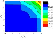
The energy dissipation is not the same in different orientations and different anisotropic materials, so we can choose materials to control the growth processes as well as the microstructure of materials. The effects of lattice and resistivity parameters on the energy dissipation are shown in Fig. 2, where the range of the ratio of lattice length is from 0 to 5 and the range of the ratio of resistivity is from 0 to 5, respectively. Based on this calculation, we find that the energy dissipation for different material parameters has a huge difference, the value of energy dissipation is from 0 to 90. We will give two examples to discuss the relationship between energy dissipation and orientations for different anisotropic materials.
 | Fig. 2. Energy dissipation varies with the ratio of lattice lengths and the ratio of resistivity. |
As the first example, the materials with the ratio of resistivity ρ x/ρ z = 0.5 and the ratio of lattice length c/a = 0.5, 1.5, 2.5, 5.0 are chosen respectively, whose simulation results are shown in Fig. 3. The relationship between angles θ and ϕ is approximately the series of slope lines shown in Fig. 3(a), whose pattern formation is similar to a group of strip phases. The Joule heating has the lowest value in the second strip. The larger energy dissipation will occur in the larger θ and the lower ϕ range. The different pattern can be seen in Fig. 3(b), in which lower Joule heating is located in most ranges and larger Joule heating is in larger ϕ and lower θ range. For the condition of ρ x/ρ z= 0.5, c/a = 2.5, the relationship between the energy dissipation and orientation is plotted in Fig. 3(c), where the lower energy dissipation appears in most ranges; this case is different from the case shown in Fig. 3(b), where the larger energy dissipation will be in both larger and lower ϕ and lower θ ranges. The other interesting phenomena occur in Fig. 3(d), the energy dissipation is lower in almost all ranges, but the higher energy dissipation occurs in the lower θ and ϕ range.
 | Fig. 3. Energy dissipation as a function of the angles along the longitudinal and transversal directions: (a) ρ x/ρ z= 0.5, c/a = 0.5, (b) ρ x/ρ z = 0.5, c/a = 1.5, (c) ρ x/ρ z= 0.5, c/a = 2.5, (d) ρ x/ρ z = 0.5, c/a = 5.0. |
The second example is the material with the ratio of resistivity 1.5 and the ratio of lattice length c/a = 0.5, 1.5, 2.5, 5.0 respectively. The relationship between the energy dissipation and the angles along the longitudinal as well as transversal orientations is illustrated in Fig. 4. The middle strength of energy dissipation (from 0.75 to 3.5) is in most ranges as we can observe in Fig. 4(a) that the larger energy dissipation will occur in the larger θ and the lower ϕ . From Figs. 4(b) and 4(c), we can find that Joule heating is lower in all ranges (the maximal value is 2.8). However, as shown in Fig. 4(d), the largest Joule heating is approximately 12, which is much larger than that shown in Figs. 4(b) and 4(c). In terms of the above simulation, we can see that the material parameters with ρ x/ρ z, c/a = 1.5 or 2.5 have the lower energy dissipation. In other words, our models and calculations can be helpful for choosing a suitable anisotropic material.
 | Fig. 4. The effect of energy dissipation with different material parameters: (a) ρ x/ρ z = 1.5, c/a = 0.5, (b) ρ x/ρ z = 1.5, c/a = 1.5, (c) ρ x/ρ z = 1.5, c/a = 2.5, and (d) ρ x/ρ z = 1.5, c/a = 5.0. |
The multigrain structures are an interesting and important subject in metallic physics[37] and nano-scale physics.[38– 40] It is assumed that every grain is uniform and the same electric current, and θ i is the angle between the horizontal direction and the electric current direction in the i-th grain. We assumed that ϕ angle is fixed as zero for every grain. This case likes a series circuit because grains are arranged in a chain, where the electric current for every grain is the same. Meanwhile, the condition of a constant electric current has been applied in the previous models; it is proved that the electric field for every grain can be calculated. Therefore, the total average electric power is the sum of the electric power for every grain. According to this idea, two specific cases will be discussed. The first is the multigrain with the repeatable configuration for two layers, which has two repeatable AB layers, i.e., the multilayer structures are ABAB· · · AB; we called these multilayers the AB stack.[41, 42] The second case is the sandwich structure, which only consists of three layers and forms an ABC stack.
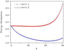
Figure 5 plots the relationship between the energy dissipation and the configuration of multigrain with repeatable two layers, where the parameters of the A layer are the length ratio c/a = 1.5 and resistivity ratio (ρ x/ρ z = 2.5), while the B layer’ s are (c/a = 2.5) and (ρ x/ρ z = 1.5). The relationship between the energy dissipation and different orientations is a nonlinear function. Two curves have different trends, curve 1 is an increasing function with angle θ , curve 2 exists at a minimum value of energy dissipation located at about θ = 70° . It is shown that the energy dissipation has different behaviors for different materials.
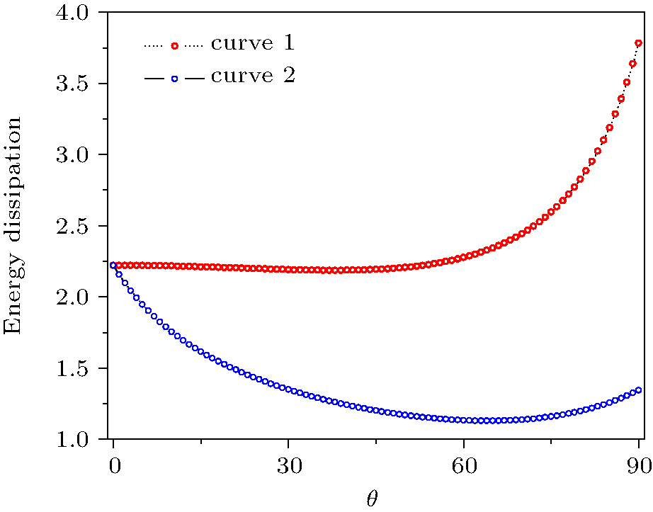 | Fig. 5. The relationship between the energy dissipation and different orientation for repeatable two layers, where the parameters of the A layer are ρ x/ρ z = 1.5, c/a = 2.5 and the parameters of the B layer are ρ x/ρ z = 2.5, c/a = 1.5. |
The multigrain can be reduced to the tri-layers: one layer with θ 1 configuration, the second layer with θ = 0, the third layer with θ 2 orientation. We select the parameters for two sandwich structures, the first sandwich structure is the ABA structure that the parameters for the first A layer are chosen as cA/aA = 1.5 and 


 | Fig. 6. Energy dissipation as a function of two different orientations θ 1 and θ 2. (a) The first sandwich structure ABA (A: ρ x/ρ z = 2.5, c/a = 1.5, B: ρ x/ρ z = 1.5, c/a = 1.5, C = A: ρ x/ρ z = 2.5, c/a = 1.5), (b) the second sandwich ABC structure (A: ρ x/ρ z= 1.5, c/a = 2.5; B: ρ x/ρ z = 2.5, c/a = 2.5; C: ρ x/ρ z = 2.5, c/a = 1.5). |
sandwich structures ABC are chosen as the first A layer with cA/aA = 1.5 and 

We present models and calculations to describe the energy dissipation of anisotropic materials. The expression of the energy dissipation in the anisotropic system in the case of constant current can be derived from the first principles. It is shown to depend on the lattice parameters and resistivity. We obtain the relationship between energy dissipation and the angles along the longitudinal and transversal directions. It is shown that the orientation variation of grain can significantly influence the energy dissipation for some anisotropic materials. On the other hand, two multigrain models are constructed. It is demonstrated that the microstructural evolution under electromigration can be radically influenced by the energy dissipation and the anisotropic configuration.
| 1 |
|
| 2 |
|
| 3 |
|
| 4 |
|
| 5 |
|
| 6 |
|
| 7 |
|
| 8 |
|
| 9 |
|
| 10 |
|
| 11 |
|
| 12 |
|
| 13 |
|
| 14 |
|
| 15 |
|
| 16 |
|
| 17 |
|
| 18 |
|
| 19 |
|
| 20 |
|
| 21 |
|
| 22 |
|
| 23 |
|
| 24 |
|
| 25 |
|
| 26 |
|
| 27 |
|
| 28 |
|
| 29 |
|
| 30 |
|
| 31 |
|
| 32 |
|
| 33 |
|
| 34 |
|
| 35 |
|
| 36 |
|
| 37 |
|
| 38 |
|
| 39 |
|
| 40 |
|
| 41 |
|
| 42 |
|