Peng Shi-Xiang†, Zhang Ai-Lin, Ren Hai-Tao, Zhang Tao, Xu Yuan, Zhang Jing-Feng, Gong Jian-Hua, Guo Zhi-Yu, Chen Jia-Er. Continuous operation of 2.45-GHz microwave proton source for 306 hours with more than 50 mA DC beam . Chinese Physics B, 24(7): 075203
Permissions
Continuous operation of 2.45-GHz microwave proton source for 306 hours with more than 50 mA DC beam
*Project supported by the National Basic Research Program of China (Grant No. 2014CB845502) and the National Natural Science Foundation of China (Grant No. 91126004).
Abstract
This paper describes a long-term operation of the 2.45-GHz microwave proton source at Peking University. The DC proton beam of 50–55 mA with energy of 35 keV has been run for 306 hours continuously. Total beam availability, defined as 35-keV beam-on time divided by elapsed time, is higher than 99%. Water cooling machine failures cause all the downtime, and no plasma generator failure or high voltage breakdown is observed. The longest uninterrupted run time is 122 hours.
PACS:
52.50.Sw; 52.50.Dg; 52.59.–f; 52.80.Pi
Keyword:
ECR ion source; DC proton beam; plasma generator failure; high voltage breakdown
Several new applications for high-power proton linacs have been proposed for accelerator-driven transmutation of nuclear waste[1] and other applications, such as IPHI project (injector of protons for high intensity), [2] and so on. Those linacs typically require its proton injector to supply tens-mA proton-beam current at certain energy. At these beam parameters the ion source reliability and longevity become most important and also very challenging. Microwave proton source is a good choice as the dc ion source to generate such a high-intensity beam. CEA/Saclay has successfully developed the SILHI source for IPHI project.[2] To obtain information for better understanding of the SILHI source behaviors, CEA/Saclay person did 5 times CW mode testing during 1996– 2001. The counting CW beam running time is about 800 hours. Within those operations, the best results are obtained in late 1999 and middle of 2001. In Oct. 1999, a 114-hour DC operation at 95 keV with 75 mA H+ beam was done, and only one beam break occurred. In June 2001, a 162-hour DC operation was carried out at 95 keV/114 mA, with seven breaks and one spark. The longest non-interrupted run time was 113 hours. To qualify the microwave ion source for LEDA project at Los Alamos, [3] a 170-hour continuous run of the microwave source with 60– 65 mA H+ beam at 47 keV was performed in 1996. During that long-term operation, no plasma-chamber fault occurred. Ion beam downtime was caused by sparks in the high voltage column of extraction system and one gas flow control problem. The longest uninterrupted run time was five hours. As a partner of CADS project, Peking University (PKU) is undertaking the R& D program on high current DC hydrogen ion source development. Reliability and longevity of that source are the essential requirements.
In the past decade, PKU ion source group has developed high-intensity beam permanent magnet 2.45-GHz ECR ion sources (PKU PMECRIS) for O+ , [4] D+ , [5] He+ , [6] and H+ [7] in pulse mode with duty factor less than 16% . The first CW H+ ion beam was produced in 2011. A 96.3 mA/50 keV H+ beam was obtained through a ϕ 6 mm emission aperture.[8] Recently, specific tests have been performed to check the source reliability, availability for 50 mA/35 keV CW H+ beam with upgraded PKU PMECRIS.
2. Experimental setup
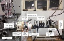
This experiment was performed on PKU Ion Source Test Bench. Figure 1 shows the 2.45-GHz microwave waveguide, the gas flow inlet valve and PE pipe, high-voltage break-up, the source body, the 50-keV acceleration columns, and the beam diagnostic box with a faraday cup inside.
Fig. 1. Installation of PKU ion source test bench.
The ECR source operates at 2.45 GHz and the 875 Gauss ECR axial magnetic field is provided by permanent magnets. The RF power is fed to the source through ceramic microwave window, which is the weakest part of PKU PMECRIS with counting lifetime less than 200 hours. With a high voltage breakup waveguide, most of source ancillaries, including microwave components (microwave isolator, circulator, manual tuner, microwave head, microwave generator) and gas cylinders are located on the ground level. The water-cooled ion source body, which is the only thing located in high voltage region, is cooled with a small separated water cooling machine, called High Voltage Cooling Water Machine (HVCW) in this paper. This water machine is isolated from ground potential and powered through an isolation transformer. With such arrangement high voltage region is limited within a ϕ 160 mm× 100 mm area. A three-electrode extraction system is used and the diameter of the plasma electrode emission aperture is 6 mm. All electrodes are water cooled. A 20-kW cooling water machine (that locates on ground level) is used for all the facilities that located on ground level. The H+ beam was dumped on a water cooled faraday cup. It is installed downstream the extraction system.
3. Ion source availablility and longevity test
3.1. General layout
Before starting the ion source longevity test, some modification and improvement were performed in advance. The reasons are as follows. First, our previous experimental results indicate that the microwave window life time of PKU 2.45-GHz ECR ion source is less than 200 hours. Second, facilities like the faraday cup was developed for low power beam operation. Third, there is no automatic control system except several high-voltage power supplies. The most serious thing is that we never did a more than 8 hours long-term beam continuous operation on our test bench.
Modifications and developments include upgrading the source body with more water cooling, especial more powerful cooling around the RF window, modified the extraction system with water cooling for each electrode, designing a new more powerful water cooled copper based molybdenum liner beam stop as faraday cup, separating cable path and shielding for signals and power, installing EMI hardened devices for all sensitive electronics and PLC, galvanic insulation of analog and digital signals, monitors and alarms, etc. Unfortunately, we did not develop the beam current feedback and automatic gas flow feed through. The other unlike thing is that we did not anticipate the defect of HVCW. We had two HVCW machines. The old one has been used to cool our source body since 2006 and no failure occurred in the past years. The new one was bought last summer and it worked well all the time.
3.2. Preliminary tests
To verify the efficiency of the above modifications, near ten times short-term continuous operations were carried out. During those tests, gas pressure inside our diagnostic box was set at 1.7 × 10− 3 Pa, RF power from microwave generator was 750 W, the extraction voltage was 35 kV, the voltage of second electrode was − 2 kV. The current displayed in faraday cup is about 50 mA. For each continuous run, all above parameters were kept without any interference. Beam recorded at FC is very stable all along the elapsed clock time. The total running time before our long-term operation was about 60 hours.
3.3. Two weeks continuous operation in CW mode
Long-term CW hydrogen-ion beam runningtest was performed during the period from January 15 to 28, 2015. The total continuous running time is 306 hours. Figure 2 shows the beam record captured from the control PC panel. During the operation the rf power from generator was set at 750 W. Vacuum inside the diagnostic chamber was 1.5 × 10− 3 Pa. The extraction voltage was 35 kV and the suppressing voltage in second electrode was − 2 kV. No gas-flow controller feedback loop, no current feedback loop for rf tuner matching was used for this run. For safety reasons, operators were present on site all along this fourteen-day long-term reliability test.
Fig. 2. Screenshot of the monitor computer at the end of longevity test. Top: instantaneous current, counting hours and instantaneous FC temperature. Middle: beam current versus elapsed time. Bottom: FC water temperature.
As shown in Fig. 2, there are five beam breaks during this 306-hours longevity test. They occurred at 62, 80, 127.5, 138, and 259.7 hours after the start of test, respectively. The previous four beam breaks were caused by the failure of HVCW. Those problems were solved by replacing the ion source cooling water machine with a repaired one. The last stop that happened on the early morning of January 26, 2015 was due to the fact that the pressure of the ground level cooling water was lower than the threshold for microwave generator operation. By replacing the blocked filter with a new one, the circular water pressure come back to normal pressure (3 atm) and the microwave generator resumed to work. The total counting non-beam time is about three hours. The beam availability, defined as 35-keV beam-on time divided by elapsed time, is 99% . Eliminate the water machine maintaining period, the average current for 303 hours is about 53 mA. Neither the high-voltage breakdown nor plasma generator failure was observed. It is predictable that our present PMECRIS availability can reach 100% for 300-hours continuous operation if there is no cooling water trouble. Even with troubles caused by cooling water, the longest uninterrupted run time was about 122 hours.
3.4. Discussion
During this experiment, some beam current fluctuation and about eight beam current drops were observed in Fig. 2. Room-temperature fluctuation and the pressure changing inside the hydrogen cylinder are the main reasons for beam fluctuations. We did not use air conditioning during the experiment, so the room temperature reached 24 ° C in noon time and drop to 16 ° C in the early morning. The temperature changing affected the gas pressure within the PE gas inlet pipe, and the gas flows inside the discharge chamber also fluctuated accordingly. This problem was solved through opening/closing the windows at different times every day.
In Fig. 2, it is easy to find that the beam current stability becomes worse during the last day operation. This phenomenon was caused by the pressure drop inside the H2 gas vessel. During our experiment a 2 liter volume vessel was used, and it had been used for some time. After nearly two week operation, the pressure dropped to less than 10 atm, and the gas flow outlet from the gas store could not keep constant.
4. Conclusion
After completion of the fourteen day running, the ion source was inspected for wear or component failure. No obvious signs of wear were found, and it is unknown how long the source could run before failing. Including the previous running time the ion source longevity is now demonstrated to be greater than 360 hours. Emittance of a 60 mA/35 keV pulsed proton beam with 10% duty factor was measured after the source was reinstalled on our test bench. Its rms normalized emittance is about 0.19 π · mm· mrad. The first long-term H+ beam operation indicates that the lifetime of present PKU PMECR ion source can be greater than 360 hours. The proton beam greater than 50 mA was maintained over 306 hours with high availability. More tests will be carried out in the future. However, before the test some improvements must be made. First, a dedicated gas-flow controller with nice feedback should be used to make sure the inlet gas into source is stable. Second, the temperature in the laboratory should be kept constant. Third, a big gas vessel with plenty gas is very important for long-term running. Forth, an automatic rf tuner will be installed. The last and the most important is that a high-quality HVCW machine should be ready for the experiment.
PengS X, RenH T, XuY, ZhangT, ZhaoJ, ZhangA L, GuoZ Y and ChenJ E2014Nucl. Instru. Meth. A763120[Cited within:1]
8
RenH R, PengS X, LuP N, YanS, ZhouQ F, ZhaoJ, YuanZ X, GuoZ Y and ChenJ E2012Rev. Sci. Instrum. 8302B905[Cited within:1]
1
1990
0.0
0.0
... IntroductionSeveral new applications for high-power proton linacs have been proposed for accelerator-driven transmutation of nuclear waste[1] and other applications, such as IPHI project (injector of protons for high intensity),[2] and so on ...
2
2002
0.0
0.0
... IntroductionSeveral new applications for high-power proton linacs have been proposed for accelerator-driven transmutation of nuclear waste[1] and other applications, such as IPHI project (injector of protons for high intensity),[2] and so on ...
... [2] To obtain information for better understanding of the SILHI source behaviors, CEA/Saclay person did 5#cod#x00A0 ...
1
1996
0.0
0.0
... To qualify the microwave ion source for LEDA project at Los Alamos,[3] a 170-hour continuous run of the microwave source with 60#cod#x2013 ...
1
2008
0.0
0.0
... ,[4] D#cod#x002B ...
1
2012
0.0
0.0
... ,[5] He#cod#x002B ...
1
2014
0.0
0.0
... ,[6] and H#cod#x002B ...
1
2014
0.0
0.0
... [7] in pulse mode with duty factor less than 16#cod#x0025 ...
1
2012
0.0
0.0
... [8] Recently, specific tests have been performed to check the source reliability, availability for 50#cod#x00A0 ...
Continuous operation of 2.45-GHz microwave proton source for 306 hours with more than 50 mA DC beam


 , Zhang Ai-Lin