

Influences of cavity dispersion distribution on the output pulse properties of an all-normal-dispersion fiber laser
[Li Pana), b) , Shi Leia) , Sun Qingc) , Feng Su-Juana) , Mao Qing-He†a)  ]
]
]
|
|


†Corresponding author. E-mail: mqinghe@aiofm.ac.cn
*Project supported by the National Natural Science Foundation of China (Grant Nos. 61250017, 61377044, 61275186, and 61205099) and the National Basic Research Program of China (Grant No. 2013CB934304).
In this paper, the influences of the dispersion distribution in the cavity on the output pulse properties of the all-normal-dispersion (ANDi) fiber laser are investigated. Our simulations show that, as the relative length of the dispersion fiber increases, the temporal width and the spectral bandwidth of the output pulse for an ANDi fiber laser with fixed total cavity dispersion or fiber length are decreased, while the pulse energy is enhanced and the compressed pulse width is increased. These simulation predictions have been proved by our experimental results. The reason may be that the nonlinear phase shift accumulated in the nonlinear fiber is more than that in the dispersion fiber if they have the same length.
Passively mode locked fiber lasers have attracted much attention in the past two decades because of their excellent properties and important applications in many fields such as nonlinear optics, spectroscopy, and frequency metrology.[1– 7] It is well-known that the energy and the duration of the pulse produced by the conventional soliton fiber lasers in the negative dispersion region of silica fibers are lower and wider than those of the Ti:sapphire mode locked lasers, respectively, due to the fiber dispersion and nonlinear effects and the limited gain bandwidth of active fibers as well.[8] In order to enhance the pulse energy of the mode locked fiber laser, the stretched- and the self-similar pulse mode locked fiber lasers were successively proposed by using various dispersion managements to design the cavity dispersion map with suitable normal and anomalous fiber segments, and the single-pulse energy is raised to the levels of nJ and tens of nJ, [9, 10] respectively. In 2006, Chong et al. proposed and demonstrated an all-normal-dispersion (ANDi) mode locked fiber laser without any dispersion compensation, [11] where a spectral filter is inserted into the cavity, acting as a self-amplitude modulator, to help realize the mode locking together with the nonlinear polarization evolution (NPE).[12] The pulse energy of such a fiber laser was soon enhanced to 20 nJ in 2007.[13] Since then, a lot of theoretical and experimental investigations have been done for the ANDi mode locked fiber laser.[14– 18] Previous research results have shown that the so-called dissipative soliton can be generated with the ANDi fiber laser by balancing the amplitude and phase modulations, [19] and the ANDi mode locked fiber laser may supply an opportunity to produce ultra-short pulses with much larger energy as operating the laser for the dissipative solitons can tolerate much more nonlinear phase shift compared to the other mode locked fiber lasers.[20]
However, the output properties of a dissipative soliton ANDi fiber laser are strongly related to the dispersion, the nonlinearity, the gain, and the spectral filtering in the cavity and the interactions among them.[21– 24] In 2008, Chong et al. identified the influence of the total cavity dispersion on the output characteristics of ANDi fiber lasers, and showed that to minimize the pulse duration the cavity dispersion should be as small as possible, and for a fixed cavity dispersion increasing pulse energy leads to shorter pulses with more structured spectra.[25] In conjunction with this idea, it has been shown that, by increasing the total cavity dispersion with lengthening the passive fiber section, giant dissipative solitons with narrow spectrum and large pulse energy may be generated, [26– 28] or, by decreasing the total cavity dispersion very short femtosecond pulses may be achieved with the ANDi fiber laser.[29, 30] In 2009, Sayinc demonstrated that the compressed pulse under 100 fs may also be achieved for the ANDi fiber laser with large total cavity dispersion.[31] Unfortunately, almost all of those works focused on the impact of total dispersion, and there are rarely any research reports that investigate the influences of the dispersion distribution on the evolution of a dissipative soliton in the cavity and the output pulse properties of the ANDi fiber laser with fixed total dispersion.
In this paper, we study the influences of the dispersion distribution in the cavity on the output pulse properties of the ANDi fiber laser with fixed cavity dispersion. Our simulation results show that the spectral bandwidth and the temporal width of the output pulse may be narrowed while the pulse energy may be enhanced if the relative length of the single-mode fiber (SMF) before the gain fiber is lengthened for an ANDi fiber laser with a fixed fiber length. The reason is that different dispersion distributions give different nonlinear phase shifts in a resonating round-trip. With different relative lengths of the SMF before the gain fiber, the output properties of an ANDi fiber laser with fixed fiber length are experimentally investigated. The measured results for the output pulses are in good agreement with the simulations.
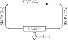
Figure 1 shows a schematic diagram of the ANDi mode locked fiber laser we study, which consists of an Yb-doped fiber (YDF), two pieces of SMFs, a saturable absorber (SA), a spectral filter (SF), and an output coupling element. For convenience in the description, the SMFs before and after the YDF along the light propagation direction in the cavity, labeled with SMF1 and SMF2 as shown, are defined as the dispersion fiber and the nonlinear fiber, respectively. If the lengths of SMF1 and SMF2 are respectively denoted by L1 and L2, the relative length of the dispersion fiber to the total single mode fiber is L1/L with L = L1 + L2.
 | Fig. 1. Schematic diagram of the ANDi mode locked fiber laser, SA: saturable absorber; SF: spectral filter. |
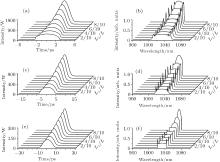
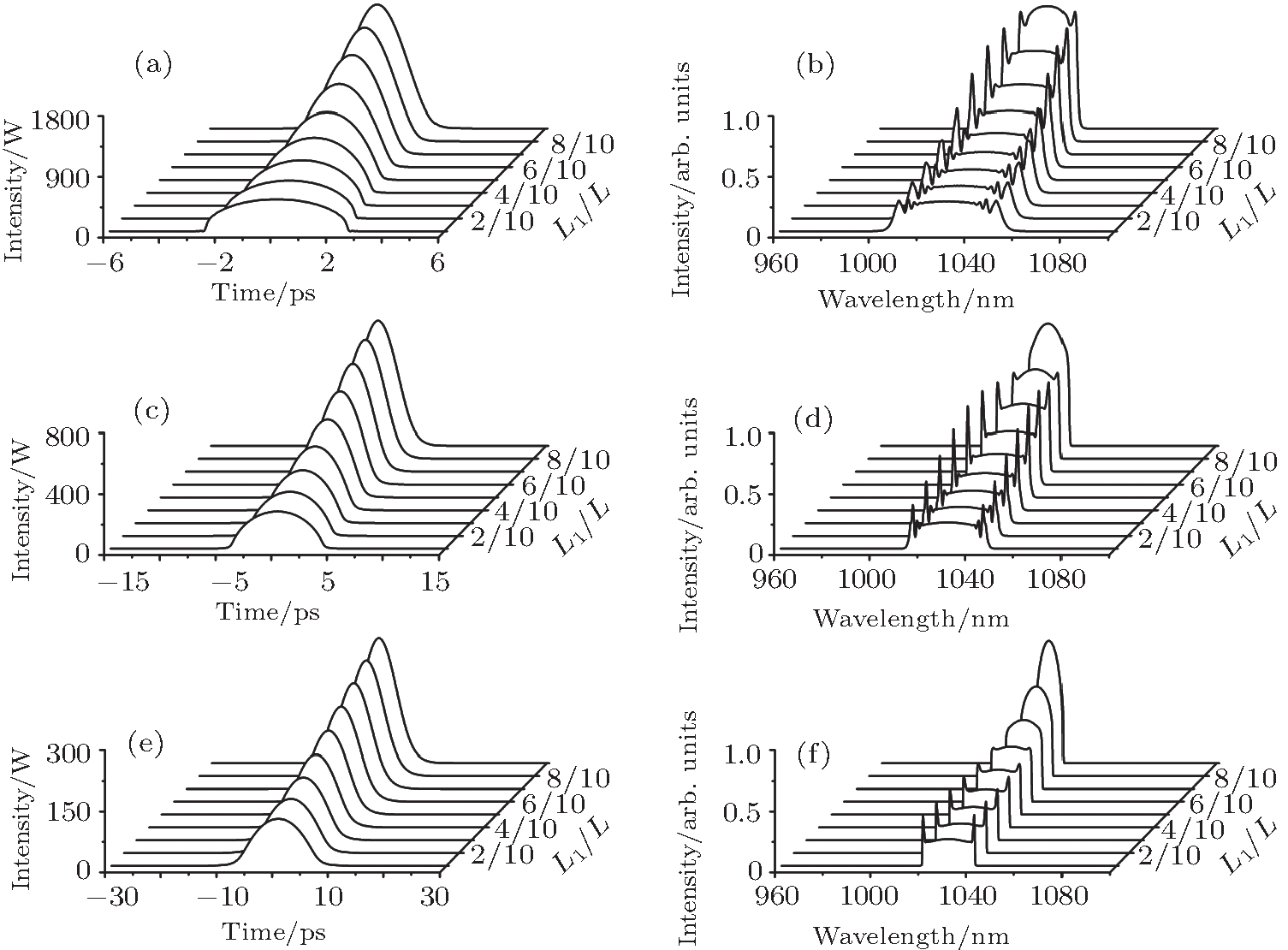 | Fig. 2. Variations of the temporal waveform (left column) and spectrum (right column) of the output pulses with L1/L. (a) and (b), (c) and (d), and (e) and (f) are the results for the fiber laser with total SMF length of 2, 4, and 8 m, respectively. |
The pulse propagating along the fibers in the cavity can be governed by the scalar nonlinear Schrö dinger equation[21]

with

where U is the amplitude of pulse envelope, z is the position in the propagation coordinate, τ is the local time, β 2 is the group velocity dispersion parameter, γ is the nonlinearity parameter, g and gss are the gain and the small-signal gain which equal to zero for the SMF, gf (ω − ω 0) corresponds to the gain spectrum with ω 0 being the center frequency, Δ ω is the gain spectral bandwidth, E = ∫ | U| 2dτ is the pulse energy and Esat is the saturation energy of the gain fiber.
The transmission of the saturable absorber may be expressed as[21]

where P(τ ) = | U| 2 is the instantaneous pulse power, P0 and q0 are the saturation power and the unsaturated loss for the saturable absorber, respectively. Here we assume that there is no other loss except for the coupling output with the output power coupling ratio of 70%.
The spectral filter may be modeled by

where Tf is the peak transmittance of the filter that is assumed to be 1 here, λ 0 and 
The output properties of the fiber laser shown in Fig. 1 may then be predicted by solving Eqs. (1)– (4). In our simulations, equation (1) was solved with the split-step Fourier method. The steady-state output pulse may be obtained by terminating the loop iterations when the relative error of the output pulse energy given by the successive loop iterations is less than 10− 8. The parameters used in our simulations are listed as follows.[21] The dispersion and nonlinear coefficients of both YDF and SMF, β 2 and γ , are identical to be 0.023 ps2/m and 0.0047 W/m, respectively; the small signal gain, gss, is 60 dB/m, the gain spectral bandwidth is 50 nm; the saturation energy, Esat, is 4 nJ; the saturation power and the unsaturated loss for the saturable absorber, P0 and q0, are 2 kW and 0.7; the filtering bandwidth is 12 nm; the center wavelengths of the gain spectrum and the filter are 1030 nm.
Initially, the influences of the dispersion distributions on the output pulse properties of the ANDi fiber lasers with different total cavity dispersions are simulated. Figure 2 shows the output pulse waveforms and spectra for the ANDi fiber lasers with fixed YDF length of 0.4 m and total SMF lengths of 2, 4, and 8 m when the value of L1/L is varied. Figure 3 shows the corresponding evolutions of the pulse width, the spectral bandwidth, and the pulse energy with L1/L. Note that both the temporal width and the spectral bandwidth are defined as the full widths at their half maximum. As seen from Fig. 2, all the output pulses exhibit typical features of the dissipative soliton, i.e., the spectral profiles have steep spectral sides and peaked edges. However, the temporal widths and the spectral bandwidths of the output pulses basically depend on the total dispersion of the cavity, i.e., the total length of the SMFs (as the YDF lengths are the same). When L1/L is 0.1, the temporal widths and the spectral bandwidths of the output pulses are 4.5, 6.7, and 10.5 ps, and 45.6, 32.6, and 22.1 nm, for the total SMF length of 2, 4, and 8 m, respectively. The temporal widths increase and the spectral bandwidths decrease with the increase of total cavity dispersion. This is because as the total dispersion increases, the temporal widths of the pulses increase, resulting in the decrease of the peak powers of the pulses, which can weaken the nonlinear effect in the cavity, this in turn decreases the spectral bandwidths. The variation tendencies of the temporal width and the spectral bandwidths with the total cavity dispersion are similar to the results in Refs. [21] and [25].
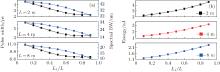
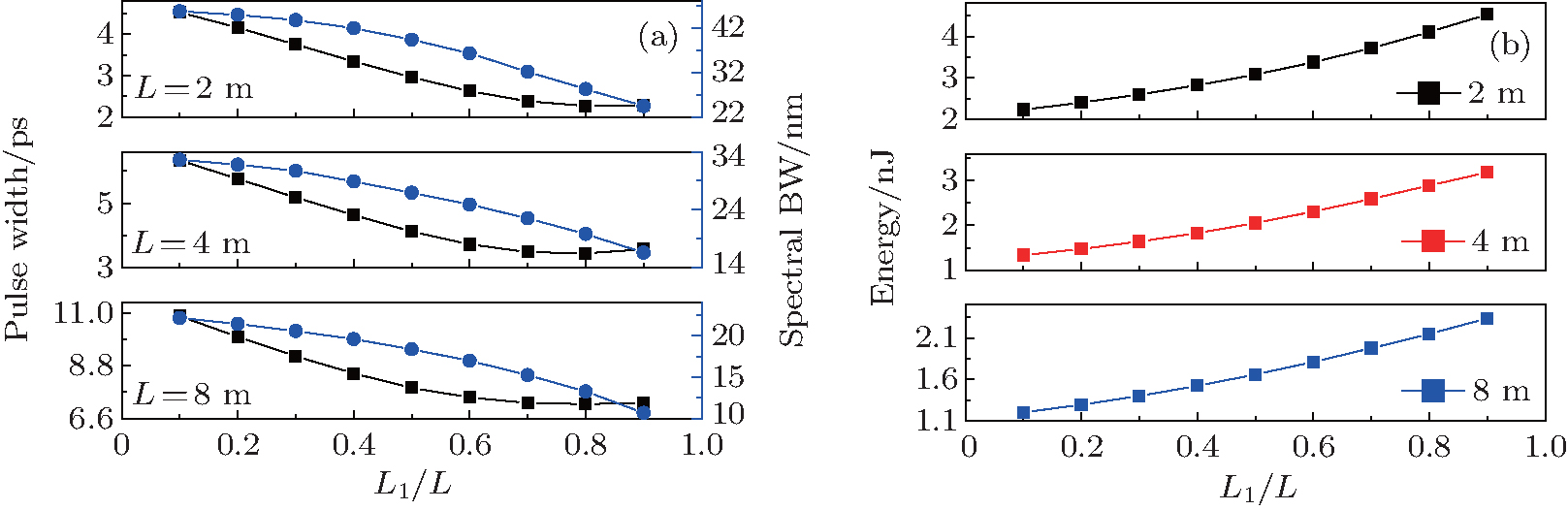 | Fig. 3. Pulse widths and spectral widths (a), and pulse energies (b) of the lasers as functions of the value of L1/L. |
For each fixed total SMF length, as the value of L1/L increases, both temporal widths and spectral bandwidths of the output pulses for all the fiber lasers are decreased. As seen from Figs. 2 and 3, when L1/L increases from 0.1 to 0.9, the temporal widths and the spectral bandwidths of the pulses generated by the fiber lasers with the total SMF lengths of 2, 4, and 8 m are monotonously decreased from 4.5, 6.7, and 10.5 ps to 2.3, 4.0, and 7.2 ps, and from 45.6, 32.6, and 22.1 nm to 24.5, 16.6, and 10.7 nm, respectively. This indicates that the temporal widths and the spectral bandwidths of the output pulses are respectively increased and decreased with the increase of the total cavity dispersion. However, they are both decreased with the increase of the value of L1/L, the relative length of the dispersion fiber. In addition, when L1/L increases from 0.1 to 0.9, the output pulse energies of the lasers with the total SMF lengths of 2, 4, and 8 m are increased from 1.93, 1.53, and 1.20 nJ to 4.23, 3.39, and 2.34 nJ, respectively. Thus, the output pulse energy is increased with the increase of the relative length of the dispersion fiber.
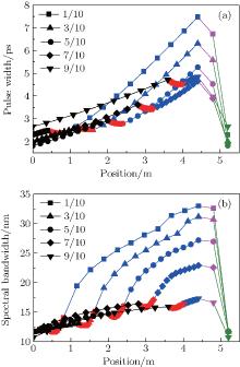
In order to investigate how the output properties of the ANDi fiber laser are affected by the relative length of the dispersion fiber, we calculated the temporal widths and the spectral bandwidths at different positions in the cavity of the ANDi fiber laser with the 4-m total SMF and 0.4-m YDF by changing the value of L1/L. The results are displayed in Fig. 4. This figure clearly shows that the temporal width and spectral bandwidth variations of the pulse successively traveling through the dispersion fiber, the gain fiber, the nonlinear fiber, the saturable absorber (output coupler), and the spectral filter in the cavity. When the pulse passes through the saturable absorber and the spectral filter, both the temporal width and the spectral bandwidth are decreased as expected. During the process of the pulse passing through the gain fiber, the temporal width is decreased meanwhile the spectral bandwidth is narrowed first and then broadened, because the pulse has to reconfigure a self-similar evolution in the gain fiber.[32] In the dispersion and nonlinear fibers, both the temporal width and the spectral bandwidth are increased. However, the effects for stretching the temporal duration and broadening the spectral bandwidth depend on the relative length of the dispersion fiber. The stretching and the broadening effects become strong with the decrease of the relative length of the dispersion fiber.
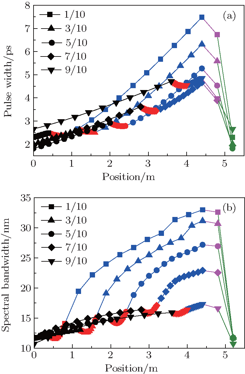 | Fig. 4. Evolutions of pulse temporal width (a) and spectral bandwidth (b) in the laser cavities with the 4-m whole SMF and 0.4-m YDF for different values of L1/L. Black, red, blue, pink, and green colors represent the pulse in SMF1, YDF, SMF2, SA, and SF, respectively. |
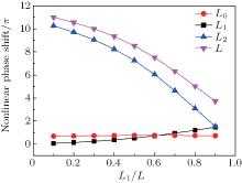
Figure 5 shows the nonlinear phase shifts accumulated in dispersion, gain and nonlinear fibers as functions of the relative length of the dispersion fiber for the laser the same as that of Fig. 4. From this figure one can see that, as the value of L1/L increases from 0.1 to 0.9, the nonlinear phase shift accumulated in the gain fiber almost remains unchanged at 0.73π , and it is greatly decreased from 10.3π to 1.52π in the nonlinear fiber though it is increased from 0.06π to 1.46π in the dispersion fiber. Thus, the total nonlinear phase shift for a resonating round-trip is still considerably decreased from 11.1π to 3.71π . In fact, the peak power of the input pulse for the dispersion fiber is relatively low because it has lost most of its energy due to the output coupling and the spectral filtering. This causes the nonlinear phase shift accumulated in the dispersion fiber to increase very slowly with the increase of the dispersion fiber length. However, because of the amplification in the gain fiber, the peak power of the input pulse for the nonlinear fiber is always the highest in the cavity, much higher than that at the input end of the dispersion fiber. Thus, the nonlinear phase shift accumulated in the nonlinear fiber is much more than that in the dispersion fiber if they have the same length. Since the nonlinear phase shift accumulated in the gain fiber is almost constant, with the increase of the relative length of the dispersion fiber, the nonlinear phase shift accumulated in a resonating round-trip must be decreased if the ANDi fiber laser is given with a fixed cavity fiber length. Then, both the temporal width and the spectral bandwidth of the output pulse must also be decreased due to the decrease of the nonlinear chirps. On the other hand, since the loss caused by the spectral filter with fixed filtering parameters depends on the spectral bandwidth of the pulse that is filtered, i.e., the pulse with a narrower spectral bandwidth experiences a smaller loss, the pulse energy must be also decreased with the increase of the relative length of the dispersion fiber by considering the automatic power controlling function of the gain fiber with a given saturation energy.[33]
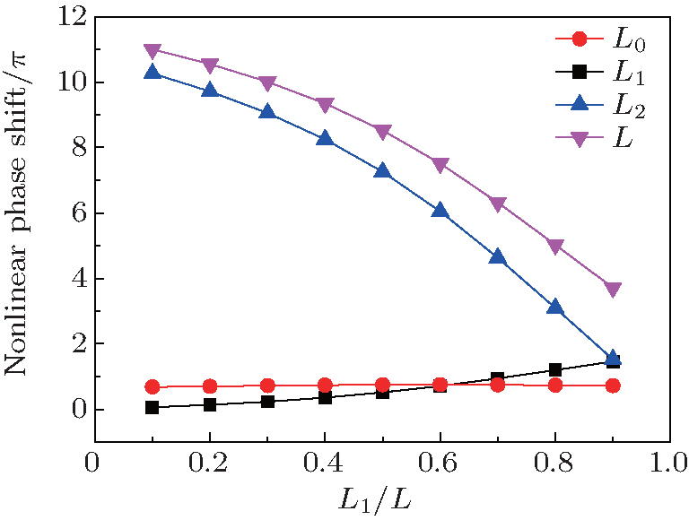 | Fig. 5. Nonlinear phase shifts accumulated in different fibers of the cavity as functions of L1/L. |
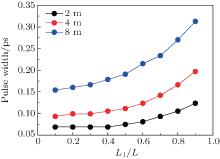
Figure 6 shows the pulse temporal widths after de-chirping by the linear phase compensation as functions of the value of L1/L for the above three fiber lasers. As shown, the compressed pulse widths for all three fiber lasers are monotonously increased with the increase of L1/L, with the one for the larger cavity dispersion increasing more. When L1/L increases from 0.1 to 0.9, the compressed pulse widths for the lasers with the SMF length of 2, 4, and 8 m are monotonously increased from 68.6, 93.1, and 154.1 fs to 123.6, 196.8, and 312.8 fs, respectively. This suggests that, for a specific fiber laser with fixed total cavity length (dispersion) and other device parameters, the compressed pulse width may be narrowed by choosing a relative short dispersion fiber.
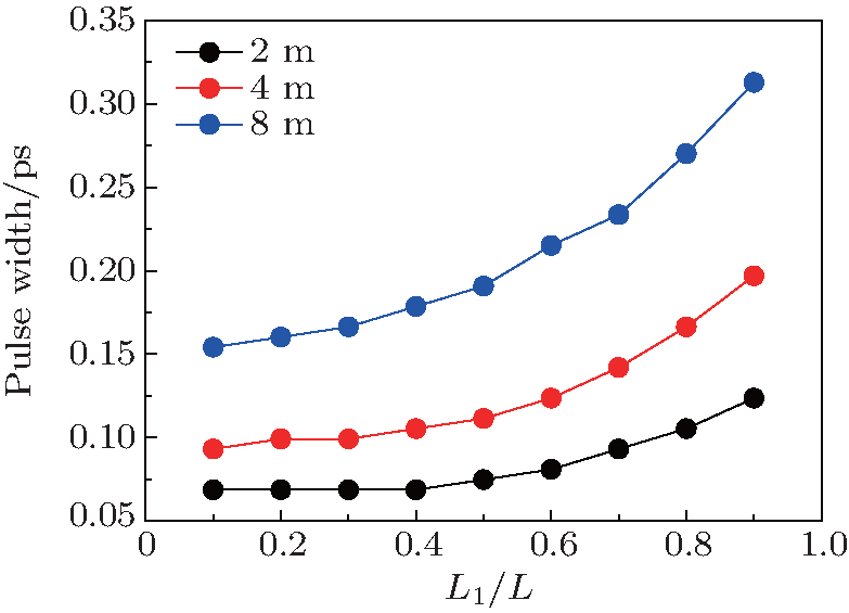 | Fig. 6. Compressed temporal widths for the three lasers as functions of L1/L. |
So far, our simulation results indicate that the output pulse properties of an ANDi fiber laser are not only impacted by the total cavity dispersion but also depend on the relative length of the dispersion fiber. For an ANDi fiber laser with fixed total cavity dispersion or fiber length, as the relative length of the dispersion fiber increases, both the temporal width and the spectral bandwidth of the output pulse are decreased, meanwhile, the pulse energy is enhanced and the compressed pulse width is monotonously increased. The essential reason may be that the nonlinear phase shift accumulated in the nonlinear fiber is much more than that in the dispersion fiber if they have the same length.
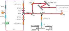
To test the validity of our simulation results, the influences of the relative length of the dispersion fiber on the output properties of the ANDi fiber laser are further experimentally investigated. Figure 7 shows the experimental setup. The gain fiber used in the ANDi fiber laser is the highly doped Yb:fiber (Coractive Yb198) with a length of 35 cm, which is pumped by a 976-nm laser diode with the maximum output power of 480 mW through a 980/1040 wavelength-division multiplexer (WDM). A half-wave plate (HWP), two quarter-wave plates (QWPs), and a polarization beam splitter (PBS) between two collimators form the saturable absorber via the NPE. The coupling loss of the collimators is about 0.7 dB. The free-space section between the two collimators is about 8-cm long and a spectral filter with the center wavelength of 1040 nm and an FWHM of 8 nm is also inserted in it. The spectral filter is an interference filter with an insertion loss of 1.5 dB. The laser output is taken from the rejection port of PBS. An isolator (ISO) with a loss of 2 dB is inserted into the cavity to ensure the pulse traveling unidirectional in the cavity. The pigtailed SMFs of ISO and WDM, together with another piece of SMF act as the dispersion fiber. All SMFs used are HI-1060 fiber, and the total SMF length remains unchanged at 3.52 m in our experiments.
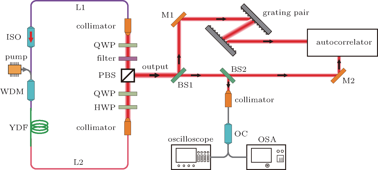 | Fig. 7. Experimental setup. PBS: polarization beam splitter; HWP: half-wave plate; QWP: quarter-wave plate; M1 and M2: mirror; BS1 and BS2: beam splitter; ISO: isolator. |
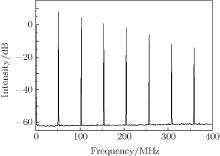
Firstly, the lengths of dispersion and nonlinear fibers were respectively selected to be 1.21 and 2.31 m, corresponding to the ratio L1/L of 0.34 and the total cavity dispersion of 0.081 ps2. It was observed in our experiments that the laser can be mode locked by carefully adjusting the three wave plates, and can self-start for the pump being set at any power between 330 and 440 mW. When the pump power is over 440 mW, the multi-pulse operation occurs.[34] Figure 8 displays the RF spectrum of the output pulse for the pump of 380 mW, which clearly shows that the repetition rate is ∼ 52 MHz. The optical spectrum and intensity autocorrelation curve of the pulses measured at the PBS rejection port are shown in Fig. 9. We can see that the spectral bandwidth is about 23 nm and has typical features of a dissipative soliton, i.e., the spectral profiles have steep spectral sides and peaked edges. By fitting with the Gaussian-shape pulse, the pulse width is about 3.79 ps according to the measured autocorrelation curve (see Fig. 9(b)). When the output pulses are compressed with a diffraction grating pair shown in Fig. 7, the pulse width is decreased to 91 fs, obtained from the measured interferometric autocorrelation trace displayed in Fig. 10(a). Figure 10(b) gives the measured average output power as a function of the pump when the laser operates for a single dissipative soliton. From this figure, we can calculate that the pulse energy is increased from 0.86 and 1.21 nJ as the pump increases from 330 to 440 mW.
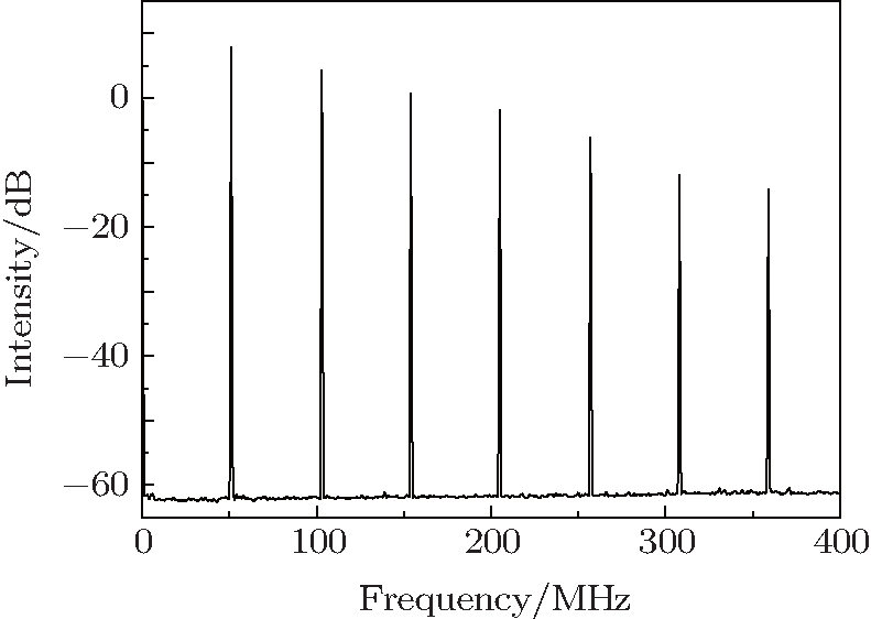 | Fig. 8. Measured radio frequency spectrum for the output pulse of the laser. |
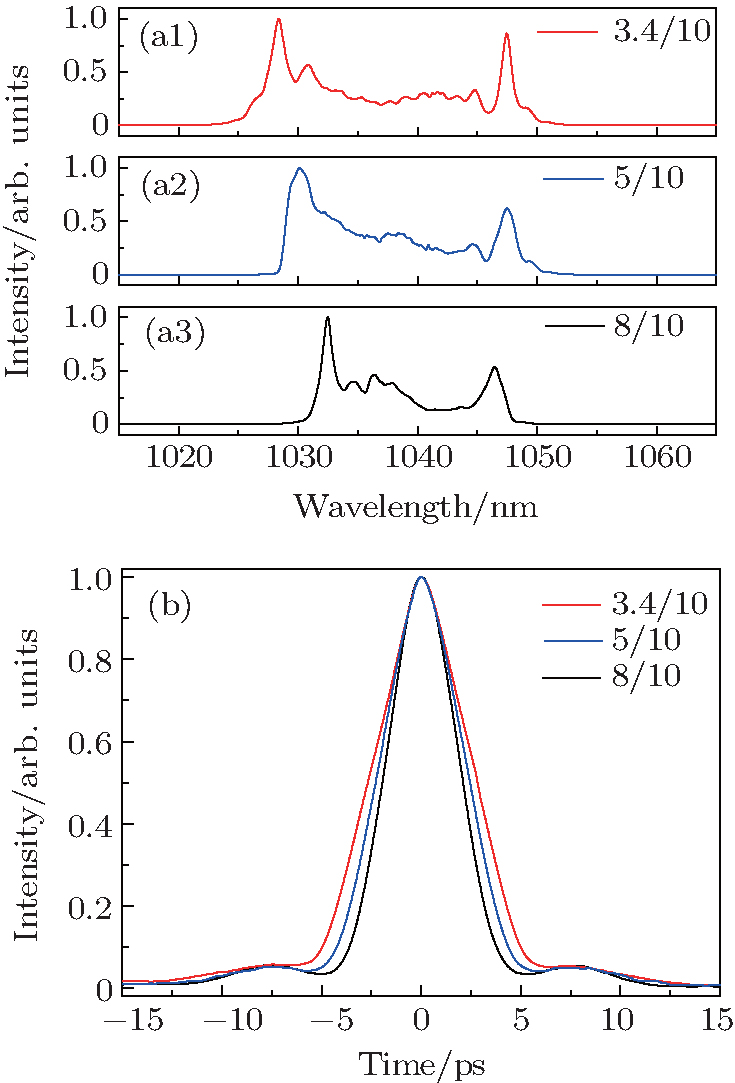 | Fig. 9. Measure spectra ((a1)– (a3)) and intensity autocorrelation curves (b) of the laser for different L1/L of 0.34, 0.5, and 0.8. |
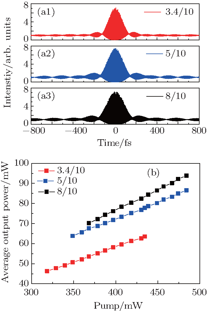 | Fig. 10. (a1)– (a3) Measured fringe-resolved autocorrelation traces and (b) average output powers as functions of the pump for different L1/L of 0.34, 0.5, and 0.8. |
Then, the output properties of the laser were investigated when L1/L was changed to 0.5 and 0.8 respectively while the total SMF length was kept the same. It was observed that the laser can be mode locked to operate in single dissipative soliton output when the pump was over 350 and 370 mW for L1/L of 0.5 and 0.8, respectively. The multi-pulse output phenomena were not observed even when the pump was increased to 480 mW which is the maximum output power of our pump source. The RF measured spectra are almost the same as that shown in Fig. 8 and not given here. The output optical spectra, autocorrelation curves before and after the grating pair compressor for the pump of 380 mW are shown in Figs. 9 and 10. Obviously, the output pulses excited from the lasers with L1/L of 0.5 and 0.8 are also dissipative solitons. The spectral bandwidths and the pulse widths for L1/L of 0.5 and 0.8 are 19 and 16 nm, and 3.24 and 2.76 ps, respectively. This verifies our simulations that both the spectral bandwidth and the pulse width are truly decreased with the increase of L1/L. After being compressed by the grating pair, the pulse widths are decreased to 106 and 118 fs, respectively. Thus, the compressed pulse width is increased with the increase of L1/L, which is also in agreement with our simulation results. As shown in Fig. 10(b), moreover, the average powers of the output pulses for L1/L of 0.5 and 0.8 are linearly increased from 63.2 to 89 mW, and from 70.2 to 93.8 mW when the pump increases from 350 and 370 mW to 480 mW, i.e., the corresponding pulse energies are increased from 1.21 to 1.71 nJ, and from 1.35 to 1.87 nJ, respectively. Therefore, our experimental results have also proved that the output pulse energy of the laser with fixed total cavity fiber length can be enhanced by increasing the relative length of the dispersion fiber.
We have experimentally verified our simulation results. However, it is worthwhile to point out that, since the experimental conditions are not strictly the same as those in the simulations, for example, the spectral filtering bandwidth used in our experiment is 8 nm while it is 12 nm in the simulations, there are some slight differences in quantity between the experimental and numerical results. Even so, the variation tendencies of the output pulse property with the relative length of the dispersion fiber for the ANDi fiber laser revealed by our simulations and experiments are completely identical.
We have investigated the influences of the dispersion distribution in the cavity on the output pulse properties of the ANDi fiber laser with fixed cavity dispersion. Our simulations indicate that the output pulse properties of an ANDi fiber laser are not only impacted by the total cavity dispersion but also depend on the relative length of the dispersion fiber. For an ANDi fiber laser with fixed total cavity dispersion or total fiber length, as the relative length of the dispersion fiber increases, the temporal width and the spectral bandwidth of the output pulse are decreased, however, the compressed pulse width is increased and the pulse energy is enhanced. The essential reason may be that the nonlinear phase shift accumulated in the nonlinear fiber is more than that in the dispersion fiber if they have the same length. The validity of our simulation results are experimentally tested with an ANDi fiber laser whose total SMF length is kept the same. The measured output pulse properties of the ANDi fiber laser for different relative lengths of the SMF have validated the simulation results.
| 1 |
|
| 2 |
|
| 3 |
|
| 4 |
|
| 5 |
|
| 6 |
|
| 7 |
|
| 8 |
|
| 9 |
|
| 10 |
|
| 11 |
|
| 12 |
|
| 13 |
|
| 14 |
|
| 15 |
|
| 16 |
|
| 17 |
|
| 18 |
|
| 19 |
|
| 20 |
|
| 21 |
|
| 22 |
|
| 23 |
|
| 24 |
|
| 25 |
|
| 26 |
|
| 27 |
|
| 28 |
|
| 29 |
|
| 30 |
|
| 31 |
|
| 32 |
|
| 33 |
|
| 34 |
|