Wang Xiao-Xiao, Sun Jia-Xiang, Sun Yuan-Hang, Li Ai-Jun, Chen Yi, Zhang Xiao-Jun, Kang Zhi-Hui, Wang Lei†, Wang Hai-Hua‡, Gao Jin-Yue. Image information transfer via electromagnetically induced transparency-based slow light . Chinese Physics B, 24(7): 074204
Permissions
Image information transfer via electromagnetically induced transparency-based slow light
Wang Xiao-Xiaoa), Sun Jia-Xianga), Sun Yuan-Hanga), Li Ai-Juna), Chen Yib), Zhang Xiao-Junc), Kang Zhi-Huia), Wang Lei†a), Wang Hai-Hua‡a), Gao Jin-Yuea)
College of Physics, Jilin University, Changchun 130012, China
Institute of Atomic and Molecular Physics, Jilin University, Changchun 130012, China
Changhun Observatory, National Astronomical Observatories, Chinese Academy of Sciences, Changchun 130117, China
*Project supported by the National Basic Research Program of China (Grant No. 2011CB921603), the National Natural Science Foundation of China (Grant Nos. 11374126, 11347137, 11204103, 11404336, and 11204029), and the Fund for Fostering Talents in Basic Science of the National Natural Science Foundation of China (Grant No. J1103202).
Abstract
In this work, we experimentally demonstrate an image information transfer between two channels by using slow light based on electromagnetically induced transparency (EIT) in a solid. The probe optical image is slowed due to steep dispersion induced by EIT. By applying an additional control field to an EIT-driven medium, the slowed image is transferred into two information channels. Image intensities between two information channels can be controlled by adjusting the intensities of the control fields. The similarity of output images is further analyzed. This image information transfer allows for manipulating images in a controlled fashion, and will be important in further information processing.
PACS:
42.50.Gy; 42.50.Hz
Keyword:
electromagnetically induced transparency; slow light; four-wave mixing; image transfer
The technique of electromagnetically induced transparency (EIT), [1] as a quantum interference phenomenon, has been in development for decades. Previous theoretical and experimental researches have shown that EIT is an effective method to manipulate the quantum states of light fields.[2] By using EIT, the weak probe signal can be manipulated coherently and all-optically. In particular, under the EIT condition, the probe signal can be slowed and even stopped by manipulating the Rabi frequency of the control field, [3– 6] which is interpreted by the theory of dark-state polariton.[7] Many experiments on coherent manipulation of a light pulse have been reported successfully. Due to the unique properties of EIT, it can be used as a good candidate for manipulating optical images. Most light manipulations based on EIT employ light pulses with a uniform transverse profile, which do not carry a spatial image. Recently, image manipulation based on the EIT effect has earned much attention.[7– 15] Coherent manipulation of an image plays a significant role in many fields. Images provide a large capacity of information, and allow for performing multiple information processing.[8, 9] The slowing and storage of an image is obtained in EIT-driven atomic vapor.[10, 11] An image of thermal light is stored by EIT.[12] A light vortex carrying orbital angular momentum is mapped into and out of an atomic ensemble.[13, 14] Multiple image storage and frequency conversion is realized in cold atoms.[15, 16]
A further quantum information network needs to contain an essential element where information can be transferred and distributed between different information channels in a controlled fashion. This is very useful for connecting different information devices and communication lines of different frequencies. By EIT-based light storage, researchers have demonstrated not only optical information conversion, [17, 18] but also image information conversion.[16] Recently, adiabatic conversion of optical information has been performed under EIT-based slow light, [19– 21] and this method can avoid the necessity of storage operation, where the light fields do not carry image information. In this work, we extend the above investigation to image information processing, and obtain image information transfer between two information channels. Here, Pr3+ : Y2SiO5 (Pr:YSO) crystal is chosen as the experimental medium due to its spectrum properties of narrow spectrum line and long decoherence time.[22– 24] Under the EIT condition, the optical image carried by the probe pulse is slowed in the crystal. By manipulating the spectrum of applied control fields, the slowed image is transferred into two different information channels. The intensities of two output images can be adjusted by changing the intensities of the control fields. The similarity of two output images is further analyzed. This image transfer is based on slow-light (SL) four-wave mixing (FWM), and does not experience storage operation. It is expected to find practical applications in image processing and information communication.
2. Experimental configuration
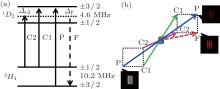
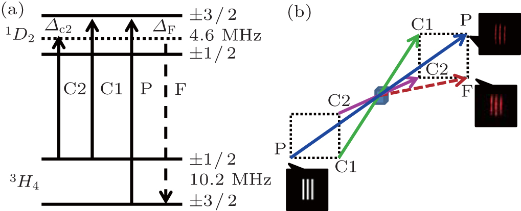
The 3H4 → 1D2 transition of Pr ions is used to demonstrate image information transfer, as shown in Fig. 1(a). The optical transition has a center wavelength of 605.977 nm. The inhomogeneous broadening of optical transition is about several GHz, and the spin inhomogeneous broadening of 10.2 MHz transition is about 30 KHz. The ground-state population decay time is about 100 s, and the spin decay time is about 500 μ s. An EIT lambda system consists of two ground states (3H4(± 1/2) and 3H4(± 3/2)) and an excited state (1D2(± 3/2)). The control-1 field ω c1 couples the transition of 3H4 (± 1/2) → 1D2 (± 3/2), and the probe field ω p couples the transition of 3H4(± 3/2) → 1D2 (± 3/2). These two fields and interacted states form a typical lambda-EIT system. An additional control-2 field is applied to realize image information transfer. The ω F field is newly generated due to slow-light four-wave mixing.
Fig. 1. (a) The level structure of a Pr ion. (b) The experimental schematic diagram of image information transfer. The powers of the control-1, control-2, and probe fields are 8 mW, 7 mW, and 0.5 mW, respectively.
The experimental schematic diagram is shown in Fig. 1(b). We use an R6G dye laser (Coherent 899) as the initial laser radiation, whose wavelength is adjusted to the center of 3H4 → 1D2 transition. The laser output splits into the experimental laser beams by using beam splitters. Each experimental beam passes through an acousto– optical modulator (AOM), which is used to control the experimental parameters (frequency, intensity, and pulse sequence) of the light fields. All experimental beams overlap spatially in the crystal with a certain angle. To obtain the optical image, the transverse structure of the probe field is encoded by a three-line mask. By using the lens, the probe image is imaged on the crystal, which is covered by other experimental beams. After passing through the crystal, the probe beam is further divided into two beams. One part is guided to the CCD camera to analyze the transverse image information, and the other part is guided to photodiode (PD) to monitor the pulse profile. Pr:YSO crystal with 0.05% dopant concentration is used as the experimental medium. The crystal is placed in a cryostat, and the temperature is kept at 3.5 K. The crystal dimensions are 4 mm× 4 mm× 3 mm. The crystal B axis along 3 mm is chosen as the light propagation direction.
3. Experimental results and discussion
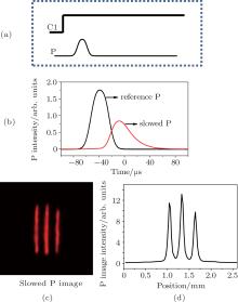
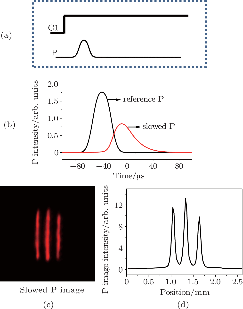
The spectrum property of Pr:YSO allows for the preparation of a single ensemble of Pr ions by applying the preparation pulse sequences. We select a group of Pr ions shown in Fig. 1 by using the pulse sequence of Ref. [25]. Through the preparation pulse sequences, the populations are pumped to the 3H4 (± 3/2) state. Subsequently, the strong control-1 field and the weak probe pulse carrying the optical image are applied to demonstrate the slow light. Under this lambda-type EIT system, the steep dispersion induces that the probe field experiences the slowing. Figure 2(a) shows the input pulse sequence of slow light demonstration. Figure 2(b) shows the slowing of the probe pulse recorded by PD. It is seen that the probe pulse has a large time delay due to the EIT effect. Figure 2(c) shows the slowed optical image carried by the probe pulse, which is recorded by CCD. The CCD is triggered after the input probe pulse completely enters the crystal, thus only record the slowed probe image. The slowed image clearly exhibits the three-line structure of the used mask. To analyze the image intensity, we deal with images recorded by CCD by using image processing software, and obtain the image intensity profile in the horizontal direction as shown in Fig. 2(d). Three intensity peaks correspond to three lines of the mask.
Fig. 2. (a) The input pulse sequences of slow light demonstration. (b) The slowing of the probe pulse recorded by PD. (c) The slowed probe image recorded by CCD camera. (d) The intensity profile of the slowed probe image.
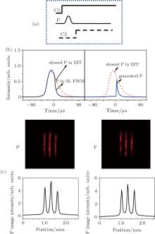
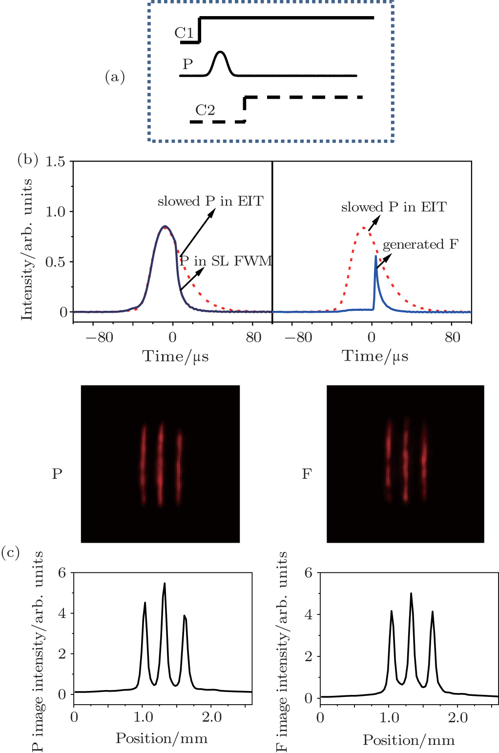
To perform the operation of image information transfer, an additional control-2 field is used. The input pulse sequence of image information transfer is shown in Fig. 3(a). The control-2 field is launched after the input probe pulse completely enters the crystal. Because of the steep dispersion induced by EIT, the probe pulse experiences a reduction of group velocity in the crystal. Under the interaction between control-1 field, control-2 field and the slowed probe pulse, a new FWM signal ω F is generated. The generation of the ω F signal is based on slow-light four-wave mixing. The slowed probe signal is transferred into a superposition of ω p and ω F signals, as shown in Fig. 3(b). The front edge of the probe pulse does not experience information transfer, and has left the crystal before the control-2 field is launched. The CCD is triggered when the control-2 field is launched, and is used to record the image information carried by ω p and ω F signals. The recorded images are shown in Fig. 3(c). It is seen that the transverse profile of generated signal ω F exhibits the same three-line image as the probe image. By this method, the initial image information is transferred into two information channels (ω p and ω F). The generation of ω F signal satisfies the two-photon resonance (Δ c2= Δ F) and phase-matching condition (KF = Kc2 + Kp − Kc1), as shown in Fig. 1. Thus, the frequency and propagation direction of optical image in ω F channel can be determined by that of the control-2 field. Compared with the probe image, the image in the ω F channel has a little distortion, which is from imperfect overlap between the applied laser beams in the interaction region. Moreover, image intensities of two information channels are analyzed. Both image intensities exhibit the similar structure of three peaks.
Fig. 3. (a) The input pulse sequences of image information transfer. (b) The probe and FWM signals recorded by PD under slow-light FWM. (c) The probe and FWM images recorded by CCD.
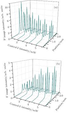
This image information transfer is related to image frequency conversion of Ref. [16]. In Ref. [16], the image information is firstly stored into atomic coherence, and then image conversion is performed by applying a new control field to scatter atomic coherence. In our case, image transfer is obtained by slow-light four-wave mixing, and does not experience storage operation. This image information transfer is based on coherent transfer of optical information in Ref. [20], where the probe field does not carry image information. In the current experiment, we demonstrate that it is possible to realize image information transfer by using the above technique. Reference [20] has shown that the intensities of two output signals are proportional to those of the associated control fields. Thus, image intensities in two information channels can be adjusted by changing the intensities of the control fields. Figure 4 shows image intensities in two information channels versus the control-2 intensity. In the experiment, we change the intensity of the control-2 field, and keep a constant intensity of the control-1 field. It is clearly seen that, when the control-2 intensity increases, the probe image intensity decreases and the FWM image intensity increases.
Fig. 4. The intensity profiles of the probe and FWM images versus the intensity of the control-2 field. (a) P image intensity, (b) F image intensity.
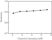
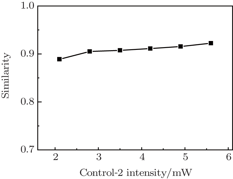
To check the ability of image information transfer, we further analyze the similarity R of the transferred FWM image compared with the probe image. The similarity R is calculated by using the formula of Ref. [16]
where Amn and Bmn are the gray-scale intensities recorded for pixels m and n of the two images to be compared. Figure 5 shows the similarity of two output images versus the intensity of the control-2 field; for different control-2 intensities, all similarities exceed 88%. The similarity is expected to keep constant, and its little variation versus the control-2 intensity comes from the background noise. The background noise of image information mainly comes from scattering light of the laboratory environment and vibration noise of experimental devices. For weak control-2 intensity, the transferred FWM signal has a weak intensity, and the signal-noise ratio of the FWM image is low. When the control-2 intensity increases, the signal-noise ratio of FWM image increases and large similarity is obtained.
Fig. 5. The similarity between output images versus the intensity of the control-2 field.
4. Conclusions
We experimentally report on an image information transfer via EIT-based slow light in a doped crystal. The optical image carried by the probe pulse is slowed in the case of EIT. By applying an additional control field to interact with the slowed probe pulse and the initial control field, the image information is transferred into two information channels. The intensities of two output images can be further manipulated by adjusting the intensity of the control field. A high similarity of two images is obtained. This image information transfer is based on slow-light four-wave mixing. This method allows for manipulating image information all-optically, and has some applications in further image information processing.
TurukhinA V, SudarshanamV S, ShahriarM S, MusserJ A, HamB S and HemmerP R2002Phys. Rev. Lett. 88023602DOI:10.1103/PhysRevLett.88.023602[Cited within:1]
24
WangL, YangQ Y, WangX X, LuoM X, FanY F, KangZ H, DaiT Y, BiS, WangH H, WuJ H and GaoJ Y2014Chin. Phys. B23014205DOI:10.1088/1674-1056/23/1/014205[Cited within:1]
... IntroductionThe technique of electromagnetically induced transparency (EIT),[1] as a quantum interference phenomenon, has been in development for decades ...
1
2005
0.0
0.0
... [2] By using EIT, the weak probe signal can be manipulated coherently and all-optically ...
1
2001
0.0
0.0
... In particular, under the EIT condition, the probe signal can be slowed and even stopped by manipulating the Rabi frequency of the control field,[3#cod#x2013 ...
1
2001
0.0
0.0
1
2013
0.0
0.0
1
2012
0.0
0.0
... 6] which is interpreted by the theory of dark-state polariton ...
2
2000
0.0
0.0
... [7] Many experiments on coherent manipulation of a light pulse have been reported successfully ...
... [7#cod#x2013 ...
1
2012
0.0
0.0
... [8,9] The slowing and storage of an image is obtained in EIT-driven atomic vapor ...
1
2013
0.0
0.0
... [8,9] The slowing and storage of an image is obtained in EIT-driven atomic vapor ...
1
2008
0.0
0.0
... [10,11] An image of thermal light is stored by EIT ...
1
2008
0.0
0.0
... [10,11] An image of thermal light is stored by EIT ...
1
2012
0.0
0.0
... [12] A light vortex carrying orbital angular momentum is mapped into and out of an atomic ensemble ...
1
2007
0.0
0.0
... [13,14] Multiple image storage and frequency conversion is realized in cold atoms ...
1
2013
0.0
0.0
... [13,14] Multiple image storage and frequency conversion is realized in cold atoms ...
2
2013
0.0
0.0
... 15] Coherent manipulation of an image plays a significant role in many fields ...
... [15,16] ...
5
2013
0.0
0.0
... [15,16] ...
... [16] Recently, adiabatic conversion of optical information has been performed under EIT-based slow light,[19#cod#x2013 ...
... [16] ...
... [16], the image information is firstly stored into atomic coherence, and then image conversion is performed by applying a new control field to scatter atomic coherence ...
... [16] ...
1
2002
0.0
0.0
... By EIT-based light storage, researchers have demonstrated not only optical information conversion,[17,18] but also image information conversion ...
1
2006
0.0
0.0
... By EIT-based light storage, researchers have demonstrated not only optical information conversion,[17,18] but also image information conversion ...
1
2006
0.0
0.0
... [16] Recently, adiabatic conversion of optical information has been performed under EIT-based slow light,[19#cod#x2013 ...
2
2007
0.0
0.0
... [20], where the probe field does not carry image information ...
... Reference [20] has shown that the intensities of two output signals are proportional to those of the associated control fields ...
1
2011
0.0
0.0
... 21] and this method can avoid the necessity of storage operation, where the light fields do not carry image information ...
1
2004
0.0
0.0
... [22#cod#x2013 ...
1
2002
0.0
0.0
1
2014
0.0
0.0
... 24] Under the EIT condition, the optical image carried by the probe pulse is slowed in the crystal ...
1
2007
0.0
0.0
... [25] ...
Image information transfer via electromagnetically induced transparency-based slow light
[Wang Xiao-Xiaoa), Sun Jia-Xianga), Sun Yuan-Hanga), Li Ai-Juna), Chen Yib), Zhang Xiao-Junc), Kang Zhi-Huia), Wang Lei†a), Wang Hai-Hua‡a), Gao Jin-Yuea)]


 , Wang Hai-Hua‡