

Giant transmission Goos–Hänchen shift in surface plasmon polaritons excitation and its physical origin
[Yang Yang, Liu Ju, Li Zhi-Yuan† ]
]
]
|
|


†Corresponding author. E-mail: lizy@aphy.iphy.ac.cn
*Project supported by the National Basic Research Program of China (Grant No. 2013CB632704) and the National Natural Science Foundation of China (Grant No. 11374357).
Excitation of surface plasmon polaritons (SPPs) propagating at the interface between a dielectric medium and a silver thin film by a focused Gaussian beam in a classical Kretschmann prism setup is studied theoretically. We find that the center of the transmitted Gaussian evanescent wave has a giant lateral shift relative to the incident Gaussian beam center for a wide range of incident angle and Gaussian beam wavelength to excite SPPs, which can be more than two orders of magnitude larger than the silver film thickness. The phenomenon is closely related with the conventional Goos–Hänchen effect for total internal reflection of light beam, and it is called the transmission Goos–Hänchen shift. We find that this lateral shift depends heavily on the excitation wavelength, incident angle, and the silver layer thickness. Finite-difference time-domain simulations show that this transmission Goos–Hänchen shift is induced by a unique dynamical process of excitation, transport, and leakage of SPPs.
Surface plasmon polaritons (SPPs) are propagating waves confined at the metal-dielectric interface. When merged with nanophotonics, they manifest many unique physical properties, [1– 4] such as strong confinement of light information and energy at deep subwavelength size scale, and giant enhancement of local electric field intensity. These properties can find many potential applications ranging from optical integration[5] to light amplification and lasing, [6– 8] fluorescence and Raman detection, [9– 12] nonlinear optics, [13, 14] solar cells, [15] information recording, [16] catalysis, [17] and biomedical diagnosis and therapy.[18– 20] These merits and advantages strongly rely on deliberate excitation and manipulation of SPPs in various plasmonic structures and devices.
The propagation constant of SPPs at a flat dielectric-metal interface is given by a simple formula: kSPP = k0 [ɛ 2ɛ 3/(ɛ 2 + ɛ 3)]1/2, where k0 is the wave number of excitation light in vacuum, ɛ 3 (n3) and ɛ 2 (n2) are the dielectric constants (refractive index) of the dielectric medium and metal, respectively. As RSPP > n3k0, SPPs cannot be excited by directly illuminating the metal film from an environmental medium. Instead, a supplemental wave vector equal to Δ k = kSPP − n3k0 must be provided to excite SPPs at the dielectric-metal interface.
A simple and popular way to achieve excitation of SPPs is to use the classical Kretschmann prism setup, as illustrated in Fig. 1(a). A silver thin film of thickness h is deposited on the surface of a prism made from high index glass with refractive index n1 and dielectric constant 
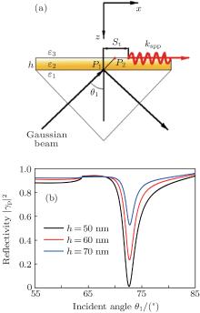
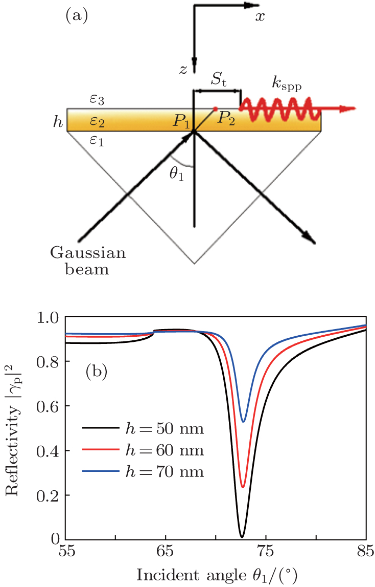 | Fig. 1. (a) Schematic of the Kretschmann prism setup used to excite SPPs by a p-polarized focused Gaussian beam incident onto the Ag layer. (b) Calculated paraxial reflectance | γ p| 2 as a function of the incident angle θ 1 for different thicknesses of the Ag layer. |
Before we go into the details of theoretical analysis, we present the geometric and physical parameters for the Kretschmann prism system as shown in Fig. 1(a). The prism is made from BK7 glass with refractive index n1 = 1.515. The wavelength of the incident Gaussian beam is λ = 632.8 nm, at which the complex refractive index of Ag is n2 = 0.1345+ 3.9863i and the dielectric constant is ɛ 2 = − 15.9+ 1.07i.[21] The background medium has a refractive index of n3 = 1.36 (ethanol). For the current problem it suffices to consider only a two-dimensional (2D) electromagnetic system where the 2D Gaussian beam and the SPP propagate in the x– z plane. The coordinate center is chosen such that the upper surface of the Ag layer is located at z = 0 and the cross point (P1) of the axis of the Gaussian beam with the lower surface of Ag layer is located at x = 0 and z = h. The Gaussian beam center is located at (xc, zc). In the following we present detailed analysis of the transmission and reflection of the incident Gaussian beam by the metal film in various situations by using angular spectrum theory.
A p-polarized Gaussian beam can be expressed as

where fi (x, z) = kx (x − xc) − k1z (z − zc), and (nx, nz) denote the dimensionless direction cosines of the wave vector k along the Cartesian coordinate axes. The Gaussian Fourier transform item is

where sx = − kx cos θ 1 − k1z sin θ 1, kx = k1 sin θ 1, k1 = n1k0, and 
where

The reflected field from the metal layer is

where fr (x, z) = kx (x − xc) + k1z (z + zc − 2h). The transmitted and reflected Fresnel amplitude coefficients for p polarization through the Ag layer are


where the parameters are defined as


On the paraxial condition, we have

The calculated paraxial reflectance | γ p| 2 of the p-polarized beam in variation with the incident angle θ 1 is shown in Fig. 1(b). Several values of Ag layer thickness, h = 50 nm (black line), 60 nm (red line), 70 nm (blue line), are considered. As we can see, for h = 50 nm, at θ 1 ≈ 72.63° , the reflectivity | γ p| 2 ≈ 0. For h = 60 and 70 nm, | γ p| 2 still reaches a minimum at the same incident angle, although the magnitude increases. According to the wave vector matching condition for SPP excitation, the incident angle to excite SPP satisfies the relationship of sin 
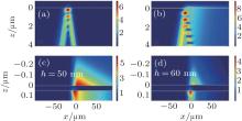
Figure 2 shows the field intensity patterns of a Gaussian beam transmitting through the prism surface at the SPR angle (θ 1 = 72.68° ) in the x– z plane with and without a 50-nm-thick Ag layer. As we can see in Fig. 2(a), without the metal layer, the transmitted Gaussian evanescent wave decays away quickly from the impinging point in both the x and z directions. However, in Fig. 2(b), in the presence of metal layer and with the excitation of SPPs, the transmitted wave above the Ag layer has a giant positive lateral shift with respect to the impinging point, and its intensity increases about fourfold. Simultaneously, the Gaussian evanescent wave exhibits a long “ tail” , indicating the excitation of the SPP wave, which propagates along the ethanol-Ag interface and attenuates gradually.
 | Fig. 2. Calculated electric field intensity patterns of a Gaussian beam transmitted through the interface at SPR angle (θ 1 = 72.68° ) in the x– z plane: (a) without an Ag layer and (b) with an Ag layer of thickness h = 50 nm. (c), (d) Enlarged distributions of electric field intensity. |
Figures 2(c) and 2(d) show the enlarged patterns of electric field intensity around an Ag layer with thickness h = 50 nm or 60 nm, respectively. In Fig. 2(c), as we can see, the center of SPP wave on the upper side of Ag layer has a lateral displacement of about 5 μ m (or 8 wavelengths) with respect to the impinging point on the bottom side. For a thicker Ag layer, h = 60 nm, as shown in Fig. 2(d), the intensity of the transmitted SPP wave becomes smaller, corresponding to a larger reflectivity in Fig. 1(b), and the lateral shift becomes a little larger.
Figure 3 illustrates the field distribution of the Gaussian evanescent wave penetrating through the Ag layer with different incident angles: (a) θ 1 = 66° , (b) θ 1 = 68° , (c) θ 1 = 70° , (d) θ 1 = 72.68° (SPR angle), (e) θ 1 = 77° , and (f) θ 1 = 79° . As we can see in Figs. 3(a)– 3(c), with θ 1 increasing to the SPR angle, the electric field intensity increases, and the positive lateral displacement and the “ tail” emerges and increases gradually. When approaching the SPR angle (see Fig. 3(d)), the lateral displacement reaches the maximum. Beyond the SPR angle, when the incident angle increases further, as shown in Figs. 3(e)– 3(f), the electric field intensity decreases and the positive lateral shift is reduced and the “ tail” disappears gradually.
 | Fig. 3. Calculated electric field intensity distribution of the Gaussian evanescent wave transmitted through the Ag layer under different incident angles: (a) θ 1 = 66° , (b) θ 1 = 68° , (c) θ 1 = 70° , (d) θ 1 = 72.68° (SPR angle), (e) θ 1 = 77° , and (f) θ 1 = 79° . |
The giant lateral displacement of Gaussian beam when it penetrates the metal film to excite SPPs reminds us of the well-known Goos– Hä nchen (GH) effect in optics. When a beam is totally reflected from a planar prism interface, there exists a tiny lateral shift of the totally reflected beam from the position predicted by geometrical optics. This GH effect phenomenon was first demonstrated experimentally by Goos and Hä nchen in 1947, [22] and was later explained theoretically by Artmann.[23] The GH shift effect has been studied both theoretically and experimentally for many years.[24– 38] Recently, various schemes have been proposed to enhance the GH effect, including a waveguide structure, [26] layered structures with left-handed meta-materials, [30, 31] photonic crystals, [32] negative refractive media, [33, 34] resonant artificial structures, [35] and surface plasmon resonance.[27]
To better understand the physical origin of the giant lateral shift of a Gaussian beam penetrating the metal film to excite SPPs, we have adopted the stationary-phase approach used to explain the GH effect[23] and derived an analytical theoretical formula for the lateral shift of the SPP coupled transmitted Gaussian beam. In this theory, the transmitted amplitude coefficient in Eq. (5) can be written as

Following Ref. [25], by comparing the real part and imaginary part, the phase difference between the incident wave and transmitted wave is given by

where N and D* represent the numerator and a complex conjugate of the denominator in Eq. (10), respectively. As in the GH shift of the reflected beam, the lateral displacement of the transmitted wave can be defined as

where kx is the parallel component of the wave vector, θ 1 is the incident angle, and ϕ t is the phase difference between the incident and transmitted waves. The final result we obtain is

where μ = (Y1 + Y2)(Y2 + Y3) and ν = (Y1 − Y2)(Y2 − Y3).
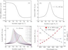
Figures 4(a) and 4(b) show the calculated dependence of phase difference ϕ t and lateral shift St of the center of the transmitted Gaussian wave on the incident angle θ 1 according to Eqs. (10)– (12). As shown in Fig. 4(a), the monotonic decrease of ϕ t with θ 1 leads to a negative slope and a corresponding positive lateral shift of the center of the transmitted evanescent wave in Fig. 4(b), and the sharp slope of ϕ t leads to a peak in the St curve. The lateral shift reaches the maximum (St ≈ 4.55 μ m) at 72.68° when the SPP wave at the interface is excited, which is in good accord with the minimum of the reflectance curve shown in Fig. 1(b) and is very consistent with the lateral displacement shown in Fig. 2(c).
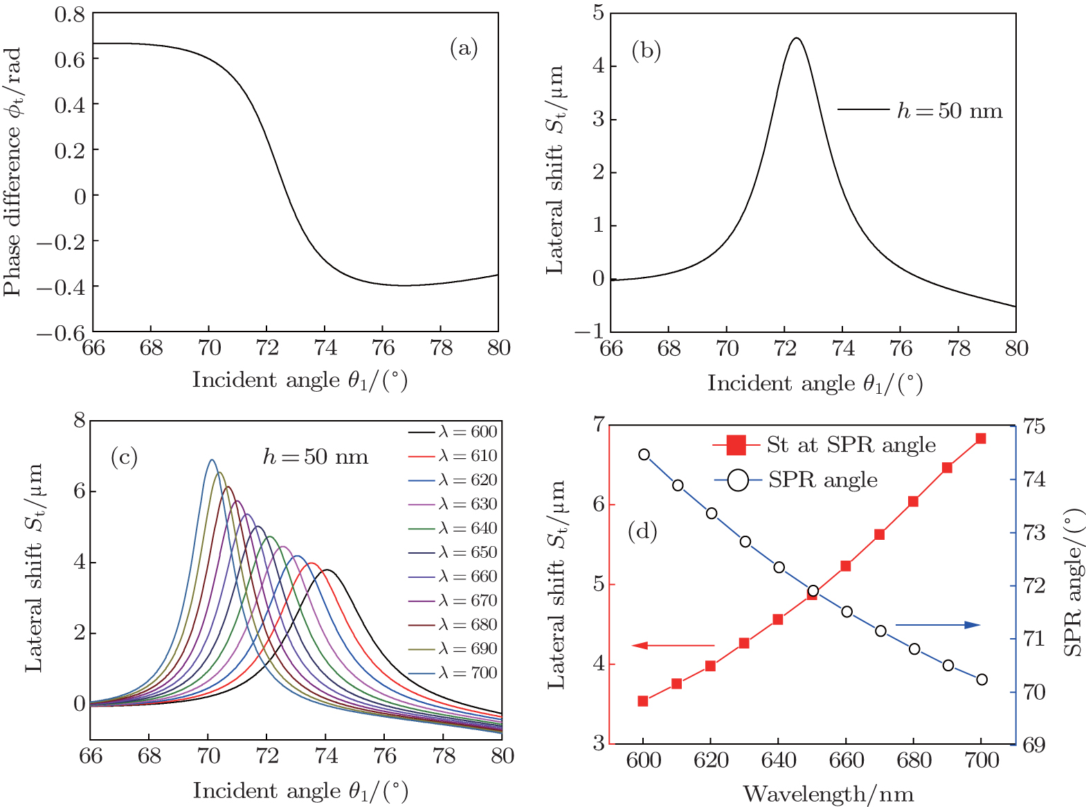 | Fig. 4. (a) Calculated phase difference ϕ t of Gaussian transmitted wave as a function of θ 1; (b) calculated lateral displacement St as a function of θ 1; (c) St as a function of θ 1 at different wavelengths; (d) left: St at different wavelengths at SPR angle; right: corresponding SPR angle at different wavelengths. |
Figure 4(c) illustrates the behaviors of the lateral shift St as a function of the incident angle θ 1 with different wavelengths ranging from 600 nm to 700 nm, where the thickness of Ag layer is fixed at h = 50 nm. The spectra clearly show that the lateral shift maximizes at the SPR angle for all the wavelengths, which further confirms that the origin of this large shift is in the excitation of SPPs at the interface. On the other hand, the transverse displacement increases monotonically with the increase of the incident wavelength, while the corresponding SPR angle decreases slightly due to the dielectric dispersion property of Ag.[21] The quantitative values of the lateral shift St at different wavelengths are displayed in Fig. 4(d) (red line) for Gaussian beam incidence at the SPR angle, whose dependence on the wavelength is also shown (blue line).
We further consider the influence of the Ag layer thickness on the GH-like lateral shift St. The quantitative value of St as a function of the Ag layer thickness in the range of 10 nm< h < 120 nm is illustrated in Fig. 5 (black line) at the SPR angle θ 1 = 72.68° . It is shown that St increases monotonically with the increase of h, and stabilizes at about h = 100 nm. At this moment, the lateral shift St ≈ 7.5 μ m. The corresponding variation of the reflectivity | γ p| 2 by the Ag layer is also shown (red line). The reflectance exhibits the minimum at h ≈ 47 nm, which means the transmitted SPP wave is maximally enhanced in this situation. While | γ p| 2 and the lateral shift St increase with the continuous increase of h, the intensity of the excited SPP wave diminishes gradually.
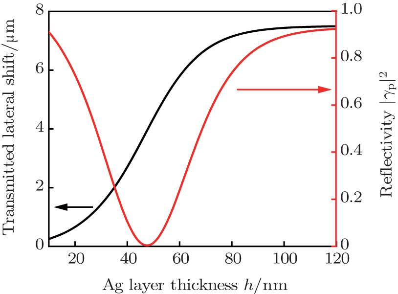 | Fig. 5. Lateral displacement St (black solid line) and reflectivity | γ p| 2 (red dashed line) as a function of the Ag layer thickness h at SPR angle of θ 1 = 72.68° . |
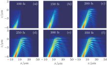
Finite difference time domain (FDTD) simulations are performed to analyze in great detail how this giant lateral shift of the transmitted SPP wave is generated and evolves. Figures 6(a)– 6(f) show the electric field intensity pattern monitored at several time points: 100, 150, 200, 250, 300, and 350 fs. The dynamics start at t = 0 when the Gaussian beam is right at the focus spot located 8 μ m below the Ag film. First in Fig. 6(a), the Gaussian beam pulse is incident on the Ag film with SPR angle (72.65° ). In Fig. 6(b), the Gaussian beam penetrates through the Ag layer and the direct reflection of Gaussian beam against the Ag film occurs. In Fig. 6(c), the directly reflected beam is generated and its interference with the incident beam leads to a series of spots. At this time, the lateral shift of excited SPP emerges and the distance of the SPP wave center from incident point is about 3 μ m horizontally. With increasing time and optical power input, as shown in Figs. 6(d)– 6(f), the SPP wave packet increases in intensity, moves away forward continuously, reaches the maximum at about 6 μ m from the incident point horizontally, and decays gradually when propagating further away. The corresponding lateral shift of about 6 μ m seen in Fig. 6(f), is very consistent with the above analytic results. The existence of large positive lateral displacements indicates forward surface propagating waves at the interface, which is greatly enhanced when the surface plasmon resonance of the metal layer is excited.[23, 27]
 | Fig. 6. Dynamics of Gaussian wave transmitting through the Ag layer at different monitoring time points: (a) 100 fs; (b) 150 fs; (c) 200 fs; (d) 250 fs; (e) 300 fs; (f) 350 fs. |
Another interesting feature is that the SPP wave decays not only through metal absorption but also through its leakage into the prism side of the Ag film, forming a readily apparent first-order bright reflection beam, in addition to the zero-order direct reflection beam. The first-order reflection beam has a standard GH shift of about 6 μ m. This shift may be the origin of experimental results in Ref. [27]. The FDTD simulation thus offers a powerful means to reveal the subtle dynamical features of SPP excitation, transport, decay, emission, and transformation with the incident and reflected Gaussian beam of various orders. It also clearly illustrates the physical origin of the GH shift in terms of both the transmitted SPP wave and reflected Gaussian beam. Notice that the excitation of SPP by a transmitted Gaussian beam with a similar large lateral shift has been shown in the framework of near-field optics; [38] however, the physical origin was not clarified without connection with the GH effect and the SPP excitation and transport dynamics.
In summary, we have investigated the transmission of a focused Gaussian beam through a silver Ag thin film coated on a classical prism to excite SPPs and found that the center of the transmitted Gaussian evanescent wave has a giant lateral shift relative to the incident Gaussian beam center. The lateral shift can be theoretically explained by referring to the usual GH effect for total internal reflection of optical beam. FDTD simulations have revealed that this transmission GH shift originates from the unique excitation, transport, and leakage properties of SPPs. As the transmission GH lateral shift strongly depends on the excitation wavelength, incident angle, the silver layer thickness, and the background dielectric constant, this effect can potentially find applications in optical sensing.[39]
| 1 |
|
| 2 |
|
| 3 |
|
| 4 |
|
| 5 |
|
| 6 |
|
| 7 |
|
| 8 |
|
| 9 |
|
| 10 |
|
| 11 |
|
| 12 |
|
| 13 |
|
| 14 |
|
| 15 |
|
| 16 |
|
| 17 |
|
| 18 |
|
| 19 |
|
| 20 |
|
| 21 |
|
| 22 |
|
| 23 |
|
| 24 |
|
| 25 |
|
| 26 |
|
| 27 |
|
| 28 |
|
| 29 |
|
| 30 |
|
| 31 |
|
| 32 |
|
| 33 |
|
| 34 |
|
| 35 |
|
| 36 |
|
| 37 |
|
| 38 |
|
| 39 |
|