
Design and optimization of terahertz directional coupler based on hybrid-cladding hollow waveguide with low confinement loss*
[Yu Ying-Ying† , Li Xu-You, Sun Bo, He Kun-Peng]
, Li Xu-You, Sun Bo, He Kun-Peng]
|
|


†Corresponding author. E-mail: yuyingying58@hotmail.com
*Project supported by the Specific Scientific and Technological Cooperation between China and Russia (Grant No. 2010DFR80140) and the National Natural Science Foundation of China (Grant No. 51309059).
We propose a design and optimization for directional coupling in terahertz hybrid-cladding hollow waveguide. It is composed of two square hollow waveguides which touch each other and are surrounded by a metallic layer. By employing the finite element method, the coupling performance and loss property are numerically investigated. Numerical results indicate that this directional coupler with hybrid-cladding can realize ultra-narrow-band coupling; it provides a low confinement loss performance: the confinement loss can reach as low as 6.27 × 10⁻⁵ cm−1. Moreover, the further analyses of configuration and performance show that confinement loss and frequency range shift for the low-confinement-loss frequency regime can be realized and optimized by appropriately tuning the thickness values of the metallic and dielectric layer. In addition, through the further analysis of coupling performance, the possibilities of realizing ultra-narrow-band couplings in different frequency ranges are demonstrated. It is a powerful candidate for high precision optical fiber sensing, and communication in terahertz splitting fields.
The terahertz (THz) waveguide and optical fiber technology has drawn a great deal of attention from researchers in recent years, owing to its potential ability to construct low loss and robust THz-integrated systems.[1– 6] Suitable THz waveguide and optical fiber can be used to direct THz beams to the correct locations and offers the possibility of creating compact THz systems. In addition, it can also be used to realize various functions of THz components, such as emitters, couplers, etc.[7– 20] As an important device in the fields of THz communication and imaging, it is crucial to develop THz directional couplers for their capability of power switching and controlling. To date, a variety of waveguide/fiber-based THz directional coupler designs, such as the mechanically down-doped core photonic crystal fiber-based THz directional coupler, [13, 14] photonic bandgap fiber-based THz directional coupler, [15, 16] subwavelength fiber-based THz directional coupler, [17, 18] and hollow waveguide THz directional coupler, [19, 20] have been proposed and demonstrated. However, among several types of THz waveguide/fiber made of directional couplers, photonic crystal fibers suffer relatively high fusion splicing loss because the air hole may distort the fiber structure during the splicing process.[21] Although subwavelengh fibers have strong coupling ability and relatively low loss, they are susceptible to environmental disturbances. Alternatively, a hollow waveguide has been proposed, it is viewed as one of the most promising candidates, because its THz wave guidance operates in the air core region which is transparent to THz radiation, and offers simple fabrication, low propagation losses, and low bend losses. A THz directional coupler based on all-dielectric hollow waveguide was demonstrated in Ref. [20]. Nevertheless, the all-dielectric hollow waveguide-based THz directional coupler has a relatively high confinement loss, the reason of the behavior is that the guiding structure of the hollow waveguide is made is that it supports leaky modes, thereby increasing the propagation loss of the device and restricting its application effectively.[22] To this end, a hybrid-cladding hollow waveguide-based THz directional coupler design is considered to reduce the confinement loss.
In this paper, we focus on the design and optimization of a THz directional coupler based on hybrid-cladding hollow waveguide. The THz directional coupler is constructed by two square hollow waveguides surrounded by a metallic layer. We first study the relation between coupling and confinement loss properties of the proposed coupler, and then study their dependences on the optimization of the metallic thickness and dielectric thickness. In addition, the confinement loss properties of the all-dielectric THz directional coupler with similar dimensions are also investigated comparatively.
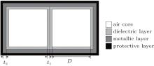
Due to a finite thickness of all-dielectric cladding, inevitable leaking of THz wave from the air core to the exterior environment occurs and results in larger confinement loss. The proposed waveguide is based on hybrid-cladding structure, i.e., the waveguide has two different material layers. This hybrid-cladding employed here is to enhance the reflection due to the interference effect of the dielectric layer when its thickness is properly chosen, and thus reduces confinement loss and improves transmission efficiency. Figure 1 illustrates the transverse section of the hybrid-cladding THz hollow waveguide directional coupler. In the figure, D is the length of the inner air core side, t1 is the dielectric layer thickness, and t2 is the metallic layer thickness. As shown in this figure, the proposed coupler comprises two all-dielectric square hollow waveguides touched together and a single metallic layer on the outer wall of the dielectric layer. Here, teflon and Cu are chosen and used for the dielectric layer and metallic layer, respectively, for the reason that the teflon has relatively low material absorption loss and Cu is one of the best reflectors in the THz range and also it has a low-cost advantage.[23– 25] When we launch the THz beam into either of the two air cores, the THz beam will couple with the adjacent core by a leaky mode nature. In what follows, we set these parameters for ensuring that the polarization modes of two air cores work at the frequency around 1 THz.
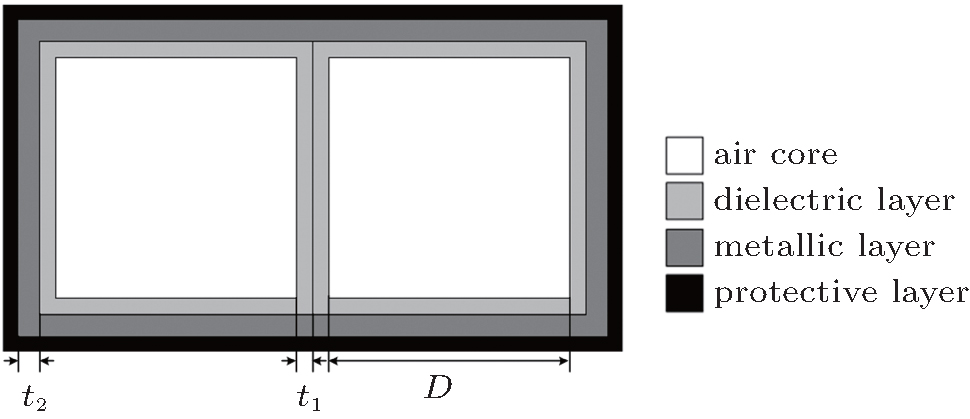 | Fig. 1. Transverse section of the hybrid-cladding THz hollow waveguide directional coupler. |
The numerical method employed in this paper is the finite element method (FEM).[26] The FEM method allows arbitrary material, shape, air hole size, and placement, which makes it a powerful approach where many other simpler and semi-analytical approaches are not satisfied.
Since THz waveguides with different metal thickness exhibit the difference in confinement characteristic for the THz wave transmission, we firstly study how the metal thickness influences the confinement loss property for the proposed THz directional coupler. The confinement loss Lc is expressed as[12]

where k0 is the wave number in free space, and neff is the effective refractive index.
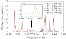
Here, the dielectric layer thickness t1 is set to be 0.22 mm, the inner air core side length D is set to be 1.68 mm, and the metallic layer thickness t2 is assumed to be a variable. Figure 2 shows the variations of confinement loss of the proposed coupler with the frequency for 0.20 mm-, 0.25 mm-, 0.30 mm-, 0.35 mm-, and 0.40-mm-thick metallic layers. From this figure, it is clearly seen that multiple large confinement loss peaks appear for the metallic layer thickness t2 = 0.20 mm and t2 = 0.25 mm in an operational frequency range from 0.95 THz to 1.05 THz, and the largest confinement loss is even as high as 0.5 cm− 1. This can be explained by the fact that the resonance occurs during the THz wave transmission due to the introduction of the metallic cladding into the THz hollow waveguide. Moreover, the inset of Fig. 2 indicates the variations of confinement loss with frequency for 0.30-mm-, 0.35-mm-, and 0.40-mm-thick metallic layers at frequencies ranging from 0.986 THz to 0.995 THz. It can be clearly seen that compared with the losses for 0.20-mm- and 0.25-mm-thick metallic layers, low loss can be realized, and the confinement loss leads to an increasing trend with the increase of the metallic thickness.
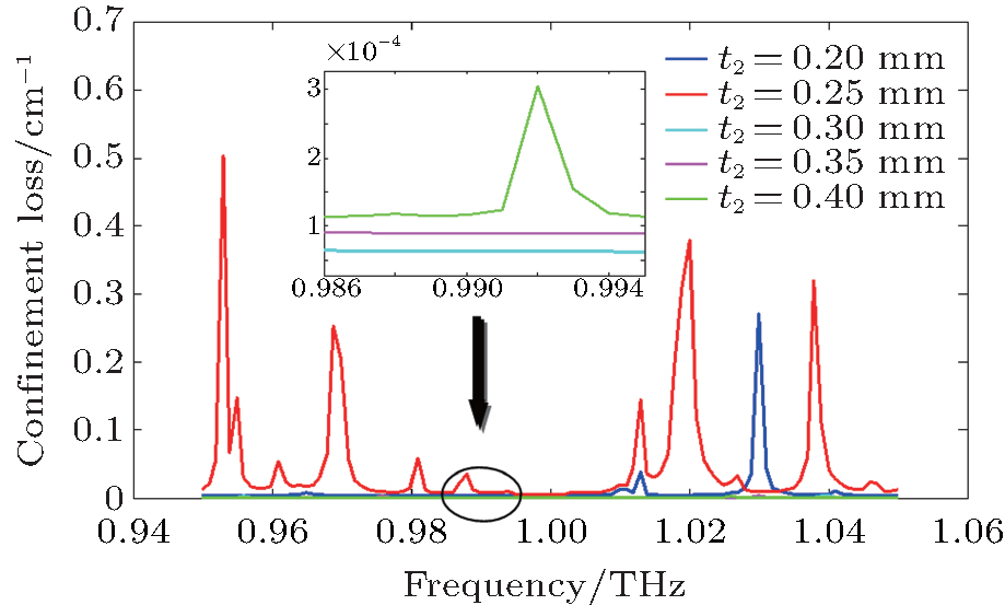 | Fig. 2. Dependences of confinement loss on the frequency for 0.20-mm-, 0.25-mm-, 0.30-mm-, 0.35-mm-, and 0.40-mm-thick metallic layers, with the inset showing the relations between the frequency and confinement loss for 0.30-mm-, 0.35-mm-, and 0.40-mm-thick metallic layers. |
In order to numerically analyze coupling performance of the proposed coupler, the coupling ratio (CR) parameter is introduced.
In general, the coupling ratio is described by the ratio between certain output power and input power, and CR is calculated from the following equation:[16]

where CR, Pout, Pin, Ld, and Lc are the coupling ratio, output power, input power, device length, and coupling length of the coupler, respectively.
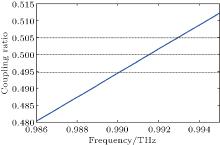
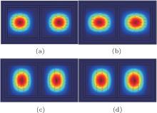
As the length of the inner air core side is 1.68 mm, the dielectric layer thickness is 0.22 mm, and the metallic layer thickness is 0.30 mm. Further, we set the device length Ld = Lc/2 ≈ 11.5 cm for the frequency f = 0.9913 THz which can realize a 3-dB directional coupling (here we call it 3-dB coupling frequency). Figure 3 shows the coupling ratio of the proposed coupler as a function of operational frequency. Generally, the effective coupling bandwidth is defined as the frequency range within which the desirable coupling ratio is plus or minus 5 percent, i.e., ± 5%. Therefore, an ultra-narrow-band coupling can be realized in a frequency range from 0.99 THz to 0.9931 THz. Meantime, taking frequency f = 0.9913 THz for example, intensity distributions of different polarization modes for the proposed coupler are shown in Fig. 4. From these figures, we can observe that the hybrid-cladding structure enables the THz waveguide without the risk of perturbing the polarization guiding modes that are confined well in both air cores.
 | Fig. 3. Variations of coupling ratio with frequency. |
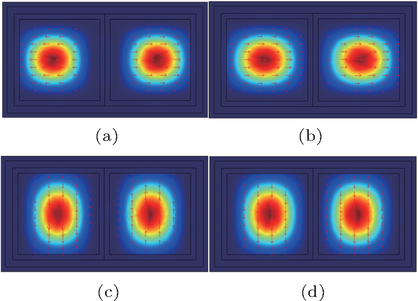 | Fig. 4. Intensity distributions of the proposed coupler at an operational frequency of 0.9913 THz for (a) x polarization, odd mode; (b) x polarization, even mode; (c) y polarization, odd mode; (d) y polarization, even mode. |
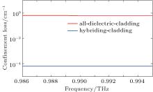
In the previous work by Lu et al., [20] the cladding of hollow waveguide is all-dielectric. Although relatively superior coupling performance can be realized, the relatively large confinement loss is still attained. Comparatively, we assume the all-dielectric-cladding hollow waveguide have the following parameter values: D = 1.68 mm and t1 = 0.22 mm, which correspond to those of our proposed hybrid-cladding hollow waveguide. Figure 5 shows the comparison of confinement loss between the all-dielectric-cladding and hybrid-cladding hollow waveguide. Obviously, the proposed design, the hybrid-cladding structure, has lower confinement loss than the all-dielectric-cladding one. Here, the confinement loss of hybrid-cladding reaches a minimum of ∼ 6.27 × 10− 5 cm− 1 in a frequency range of 0.986 THz– 0.995 THz, which is almost four orders of magnitude lower than that of all-dielectric-cladding with comparable dimensions.
 | Fig. 5. Confinement losses for all-dielectric-cladding and hybriding-cladding hollow waveguides. |
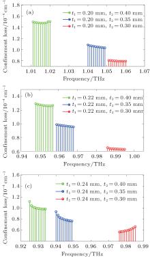
From the above discussion, it seems that relatively low confinement loss can be obtained by setting a moderate metallic layer thickness when the dielectric is fixed. In the following, we will further analyze the performance of loss and coupling for the proposed THz coupler when the thickness values of dielectric and metallic layers are both varying. Here, we refer to the frequency range in which confinement loss is low, i.e., THz wave can be transferred efficiently between two hollow waveguides, as the low-confinement-loss frequency regime. According to the previous conclusions, we set the metallic layer thickness t2 = 0.30 mm, 0.35 mm, and 0.40 mm for the reason that the lower confinement losses can be obtained with these three values. Meanwhile, we set the dielectric layer thickness t1 = 0.20 mm, 0.22 mm, and 0.24 mm corresponding to three different metallic layer thickness values respectively, and the inner air core side length is still the value of 1.68 mm. Figures 6(a)– 6(c) show the confinement loss variations of low-confinement-loss frequency regimes with frequency when both thickness values of dielectric and metallic layers are varying. As shown in these figures, from the viewpoint of confinement loss for each low-confinement-loss frequency regime, we can clearly see that the confinement loss decreases with the decrease of metallic layer thickness, with dielectric layer thickness fixed. While with metallic layer thickness fixed, confinement loss shows a general decrease trend with the increase of dielectric layer thickness. The minimal confinement loss is about 5.66 × 10− 5 cm− 1 with t1 = 0.24 mm and t2 = 0.30 mm as shown in Fig. 6(c). Furthermore, from the viewpoint of frequency range for each low-confinement-loss frequency regime, from Fig. 6, we can find that the frequency range shifts toward the high-frequency with the decrease of metallic layer thickness, with dielectric layer thickness fixed. While with metallic layer thickness fixed, frequency range shifts toward the low-frequency with the increase of dielectric layer thickness.
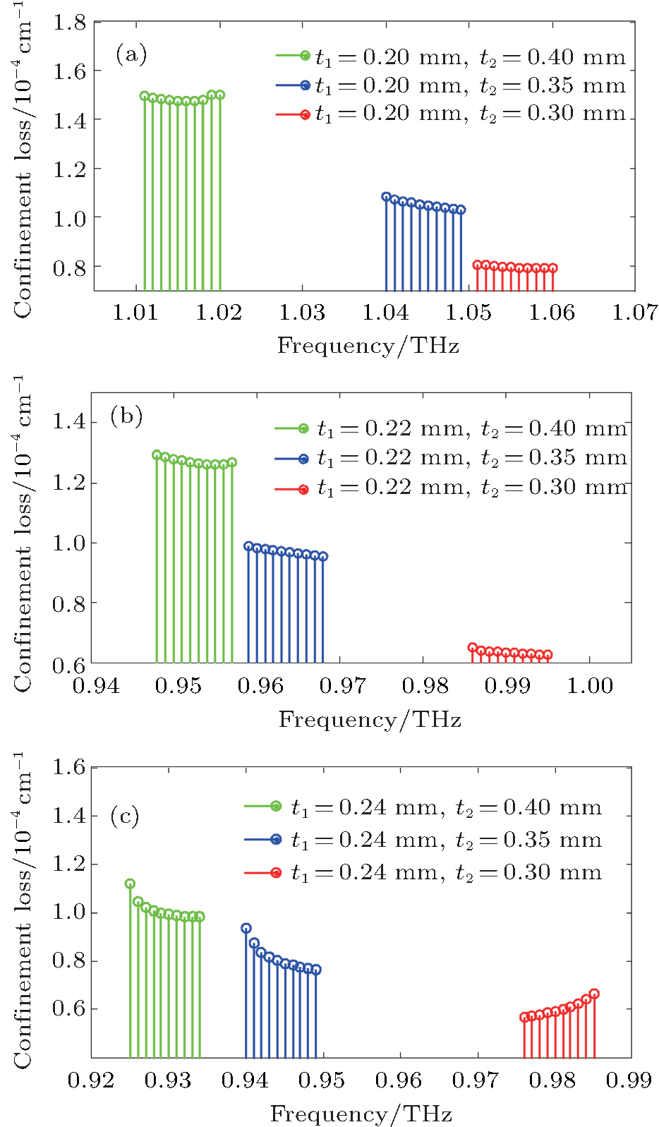 | Fig. 6. Variations of confinement loss of low-confinement-loss frequency regimes with frequency for dielectric layer thickness (a) t1 = 0.2 mm, (b) t1 = 0.22 mm, (c) t1 = 0.24 mm when metallic layer thickness t2 = 0.30 mm, 0.35 mm, and 0.40 mm. |
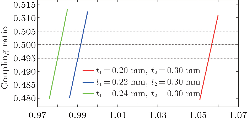
Meanwhile, from Figs. 6(a)– 6(c) it follows that the lower confinement loss can be attained when metallic layer thickness t2 = 0.30 mm for each fixed dielectric layer thickness. Thus, in order to further examine how the configuration parameter influences the coupling performance, we analyze here only the coupling ratio of the proposed THz coupler with the metallic layer thickness t2 = 0.30 mm when the dielectric layer thickness t1 = 0.20 mm, 0.22 mm, and 0.24 mm. In addition, the length of inner air core side D = 1.68 mm, and when the 3-dB coupling frequencies are set to be f = 1.0569 THz, 0.9913 THz, and 0.9824 THz, the device lengths are set to be Ld = Lc/2 ≈ 12 cm, 11.5 cm, and 14.5 cm, respectively. Figure 7 shows the variations of coupling ratio of the proposed coupler corresponding to the low-confinement-loss frequency regime with operational frequency. From this figure, we observe that the coupling bandwidths are respectively 1.0553 THz– 1.0584 THz, 0.99 THz– 0.9931 THz, and 0.9811 THz– 0.9835 THz, which are corresponding to the values of t1 of 0.20 mm, 0.22 mm, and 0.24 mm respectively, that is, ultra-narrow-band couplings corresponding to respective low-confinement-loss frequency regimes can also be realized by appropriately adjusting the dielectric layer thickness, which further demonstrates that it can be useful to adjust the dielectric layer thickness for realizing high precision THz coupling in different frequency ranges.
 | Fig. 7. Dependences of coupling ratio for each low-confinement-loss frequency regime on frequency as t1 = 0.20 mm, 0.22 mm, 0.24 mm, and t2 = 0.30 mm. |
In this paper we designed and analyzed a novel terahertz directional coupler. The proposed coupler is composed of two hollow square waveguides with hybrid-cladding. By using the finite element method, the properties of confinement loss, coupling ratio, and intensity distribution are investigated. The simulation results demonstrate that an ultra-narrow coupling can be achieved by the THz coupler with hybriding-cladding. Moreover, the proposed THz coupler offers much lower confinement losses than the THz coupler based on all-dielectric-cladding with comparable dimensions, and it can be as low as 6.27 × 10− 5 cm− 1 at frequencies ranging from 0.986 THz to 0.995 THz. At the same time, a terahertz wave can be successfully guided in both air cores with excellent mode quality. Finally, the effects configuration parameters on confinement loss and coupling performance are further investigated. By appropriately tuning the thickness values of the dielectric and metallic layer, we conclude that the better confinement loss properties for the low-confinement-loss frequency regime can be realized, and its frequency range can be shifted toward the high- or low-frequencies. In addition, through the analysis of coupling performance, we further demonstrate that our designed THz coupler is possible to realize ultra-narrow-band couplings in different frequency ranges.
| 1 |
|
| 2 |
|
| 3 |
|
| 4 |
|
| 5 |
|
| 6 |
|
| 7 |
|
| 8 |
|
| 9 |
|
| 10 |
|
| 11 |
|
| 12 |
|
| 13 |
|
| 14 |
|
| 15 |
|
| 16 |
|
| 17 |
|
| 18 |
|
| 19 |
|
| 20 |
|
| 21 |
|
| 22 |
|
| 23 |
|
| 24 |
|
| 25 |
|
| 26 |
|