

Toward the complete relational graph of fundamental circuit elements*
[Shang Da-Shan†, Chai Yi-Sheng†, Cao Ze-Xian, Lu Jun, Sun Young‡ ]
]
]
|
|


†These authors contribute equally to this work.
‡Corresponding author. E-mail: youngsun@iphy.ac.cn
*Project supported by the National Natural Science Foundation of China (Grant Nos. 11227405, 11374347, 11274363, and 11474335) and the Strategic Priority Research Program of the Chinese Academy of Sciences (Grant No. XDB07030200).
A complete and harmonized fundamental circuit relational graph with four linear and four memory elements is constructed based on some newly defined elements, which provides a guide to developing novel circuit functionalities in the future. In addition to resistors, capacitors, and inductors, which are defined in terms of a linear relationship between charge q, current i, voltage v, and magnetic flux φ, Chua proposed in 1971 a fourth linear circuit element to directly relate φ and q. A nonlinear resistive device defined in memory i– v relation and dubbed memristor, was later attributed to such an element and has been realized in various material structures. Here we clarify that the memristor is not the true fourth fundamental circuit element but the memory extension to the concept of resistor, in analogy to the extension of memcapacitor to capacitor and meminductor to inductor. Instead, a two-terminal device employing the linear ME effects, termed transtor, directly relates φ and q and should be recognized as the fourth linear element. Moreover, its memory extension, termed memtranstor, is proposed and analyzed here.
Following circuit theory, three fundamental two-terminal linear circuit elements, i.e., the capacitor C, the inductor L, and the resistor R are defined in terms of a linear relationship between two of the four basic circuit variables, namely, charge q, current i, voltage v, and magnetic flux φ , as schematically illustrated in Fig. 1(a). In 1971, Chua pointed out that there should be a fourth fundamental linear element which could be defined in terms of φ and q,

where the coefficient M is called memristance.[1] As no real circuit element that directly connects φ and q could be identified at that time, Chua made a transformation of Eq. (1) by using the relationships


and obtained

However, Chua found that the quantity M in Eq. (4) is equivalent to resistance R, and thus of no particular interest. In order to introduce some nontrivial meanings to M, Chua speculated that M might be a function of q and t instead of being a constant. In this case, a nonlinear resistive element, dubbed memristor, can be defined from Ohm’ s law

Later, Chua and Kang further generalized the concept of memristor to a much broader class of nonlinear dynamic systems, the memristive systems, [2] which are described by


where x is a vector representing the state variables of the system, and f is a continuous vector function.
Chua’ s work lay dormant for nearly 40 years without drawing much attention. In 2008, Strukov et al. demonstrated the memristor in a Pt/TiO2− x/Pt sandwiched structure that exhibits a hysteretic i– v curve.[3, 4] This discovery spurred strong interest in investigating the resistance switching mechanism, which had been the main roadblock to the commercialization of resistive random access memory devices.[5– 8] Furthermore, Chua argued that all the two-terminal nonvolatile memory devices based on resistance switching are memristors, regardless of the materials applied or physical mechanisms in operation, and he postulated that the hysteretic i– v characteristics pinched at origin are the fingerprint of a memristor.[9] With inspiration from the discovery of the memristor, the nonlinear memory counterparts of capacitor and inductor, now known as memcapacitor and meminductor accordingly, have also been proposed and experimentally demonstrated.[10– 12]
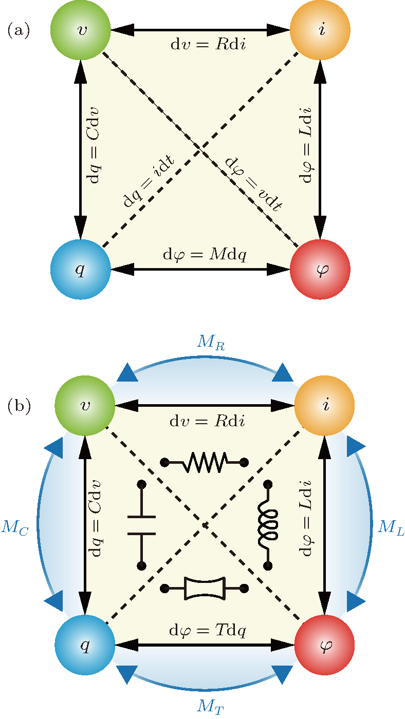 | Fig. 1. The complete relational graph of fundamental two-terminal circuit elements. (a) The four linear fundamental two-terminal circuit elements which correlate a particular pair of the four basic circuit variables, i.e., charge q, voltage v, current i, and magnetic flux φ . (b) A complete relational graph of all the possible fundamental two-terminal circuit elements, both linear and nonlinear. In panel (b), the missing fourth element, the transtor, which is anticipated to directly correlate φ with q is now denoted with T in place of M in panel (a). A symbol for transtor is introduced to facilitate later usage. The nonlinear memory devices corresponding to the four linear fundamental elements, i.e., the resistor (R), the capacitor (C), the inductor (L), and transtor (T), are now accordingly designated as memristor (MR), memcapacitor (MC), meminductor (ML), and memtranstor (MT). The relations of dφ = vdt and dq = idt in panel (a) have been omitted in (b) because they are unnecessary to define the fundamental circuit elements. |
The memristor has great potential for developing new functional devices to be applied in synapse memory, neuromorphic computing, Boolean logic operations, and so on.[13– 15] However, its physical identity as the fourth fundamental circuit element remains questionable. First of all, the memristor is obtained in practice from the i– v relationship rather than as originally proposed, from a direct relationship between magnetic flux φ and charge q. In other words, a memristor in i– v definition can work properly without invoking the basic variable φ . Second, the i– v definition of memristor from Ohm’ s law (Eq. (5)) is physically not equivalent to that of the φ – q in Eq. (1) because Faraday’ s law (Eq. (2)) to convert φ to v is applicable only in devices with a closed area under a changing magnetic field (like an inductor) or moving part under a magnetic field (like a generator), while v to φ when electric field E has a non-zero curl (∇ × E). In this sense, the memristors studied so far actually do not allow a φ – q relationship, in that it is incorrect to convert v back to φ for a resistor. Third, the linear magnetoelectric (ME) effects, which refer to the induction of electric polarization (P) by the application of a magnetic field (H) or magnetization (M) by an electric field (E) linearly, naturally lead to a linear coupling between M and P. Therefore, the linear ME effect may give a direct and linear link between φ and q, and it should be used to construct the fourth linear circuit element as already speculated by Mathur.[16]
Based on the above arguments, the memristor that operates upon the nonlinear memory i– v relationship should be viewed as the memory counterpart of the resistor, in analogy to the memcapacitor with regard to the capacitor and the meminductor to the inductor, as illustrated in Fig. 1(b). It is then very natural for us to be aware that the fourth memory circuit element which memorizes past states through which the systems have experienced in the correlation between φ and q is still lacking. The new memory element should be the counterpart of the fourth linear element based on certain specific nonlinear ME effects.
In this paper, we conceive a two-terminal model device made of ME media showing either the linear or nonlinear memory ME effects, and we prove that its circuit functions fully satisfy the requirements as the fourth fundamental elements, linear and memory, respectively. We coined the terms transtor, T, and memtranstor, MT, to denote respectively the linear and the memory actualizations of these new elements. With the introduction of the concepts of transtor and memtranstor, a complete and harmonized relational graph for the fundamental circuit variables with four linear and four memory elements, can be obtained, as shown in Fig. 1(b).
The possibility of the ME effect was first predicted by Curie in 1894 on the basis of symmetry considerations, [17] and the term “ magnetoelectric” was coined by Debye in 1926.[18] Since the renaissance of multiferroic material research in 2004, the ME effect has drawn great interest due to its promise for many applications.[19, 20] Here, we consider a device made of a block of ME medium sandwiched between two parallel electrodes, to operate with either the longitudinal (Fig. 2(a)) or transverse (Fig. 2(b)) ME effect. For a non-ferroic, linear ME medium, according to Landau’ s theory, the Landau free energy F(E, H) is given by[20]

where ε 0 (μ 0) and χ e (χ υ ) are the permittivity (permeability) of vacuum and electric susceptibility (magnetic susceptibility) of the medium, respectively, and α is the linear ME coefficient. By differentiating F(E, H) with respect to E and H, we obtain


For the model operating with longitudinal magnetoelectric effect (Fig. 2(a)), the charge q on the surface of the electrode with an area of S, is

where D = ε 0E + P is the electric displacement, ε r = χ e + 1 is the relative permittivity. The magnetic flux φ passing through the ME medium is

where B = μ 0(H + M) is the magnetic induction and μ r = χ υ + 1 is the relative permeability.
Under a constant or zero external E, a change of flux dφ will cause a change in magnetic field H by dH = dφ /μ 0μ rS (Eq. (12)), consequently a change in q by dq = α SdH (Eq. (11)). In this case, by virtue of Eqs. (11) and (12), a relation between dq and dφ is established, as speculated by Mathur, [16]

Therefore, the two-terminal model completely fulfills the original definition for the fourth linear circuit element, promising the function to linearly convert q into φ . Additionally, we should point out that in the case of a constant or zero external H a varying dq will induce conversely a change of dφ by

Similarly, for the two-terminal model device that operates with transverse ME effect (Fig. 2(b)), supposing that the area of the ME medium beneath electrodes is S, the area of the flank side is S′ . In this case, two direct relationships between dq and dφ are established as


From the above deductions, it is very obvious that the two-terminal models in Figs. 2(a) and 2(b) completely fulfill the original definition for the fourth linear circuit element, promising the function to linearly convert charge q into magnetic flux φ , and reciprocally.
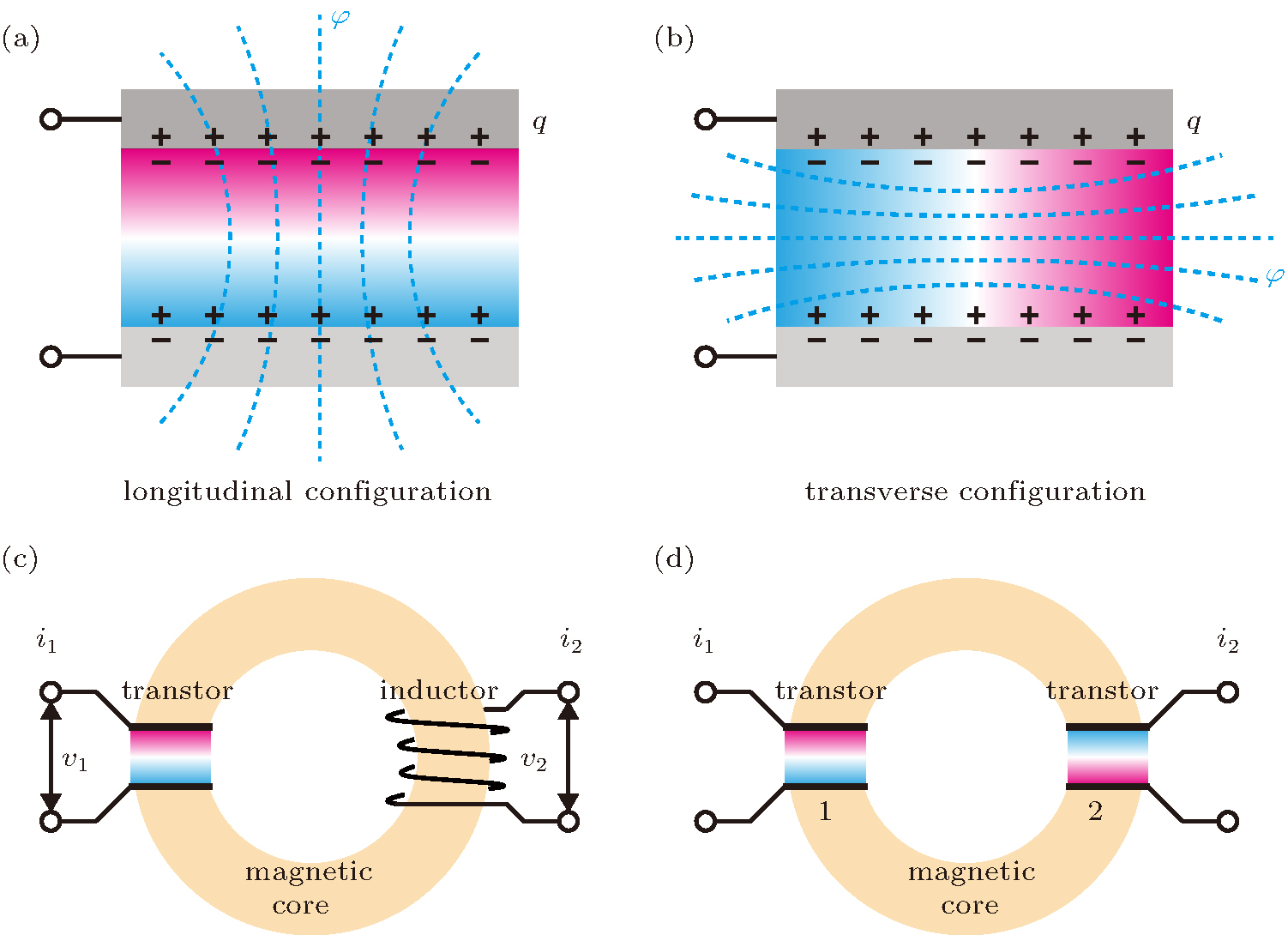 | Fig. 2. Schematic illustration of the transtive device and its exemplary implementation. (a), (b) Model transtive devices comprising an ME medium sandwiched between two parallel electrodes, realized with either a longitudinal (a) or a transverse (b) ME effect. (c) A four-terminal device design, the gyrator, with a transtor in the longitudinal configuration coupled to an inductor. (d) A four-terminal current converter design with a transtor in the longitudinal configuration coupled to another transtor. The memtranstor can also be used in the gyrator and the current converter by replacing the transtors to achieve versatile memory functionalities. |
Note that the ME media do not follow Faraday’ s law (Eq. (2)): φ – q relationship cannot be converted to v– i relationship in this case even though the coefficients defined in Eqs. (13)– (16) have the same dimension of the resistance (Ohm). Clearly, their physical meaning is definitely different from that of the resistance; they are quantities reflecting the ability of a device to convert q into φ or vice versa. Another intrinsic difference between the two quantities is that the resistance is a second-rank polar tensor while the coefficients defined in Eqs. (13)– (16) are second-rank axial tensors because α is an axial tensor while ε r and μ r are polar tensors.[21] The underlying physical origin lies in the fact that the resistance is a quantity describing a dynamic (transport) phenomena while the linear magnetoelectric, dielectric, and magnetic effects are static (equilibrium) phenomena. In the case of transport phenomena, due to the second law of thermodynamics, time reversal operation is not permissible, making resistance and memristance the polar tensors.[21] Unfortunately, it has caused lots of confusions that the fourth linear element defined by q– φ was considered as a resistor.[1, 3] Thus, it is necessary and justifiable to assign an independent name to the two-terminal linear fundamental element defined in Eqs. (9) and (10) as transtor (corresponding to resistor, capacitor, and inductor), and the corresponding coefficients (α /ε 0ε r and μ 0μ r/α ) as transtanceT (corresponding to resistance, capacitance, and inductance) to distinguish them from the memristor and memristance, respectively. We also introduced a new symbol for transtor, as shown in Fig. 1(b).
As a transtor is a circuit element made from an ME medium, it is easy to recognize that: (i) It is an independent passive linear and time-invariant element that is allowed in linear and time-invariant system theory, [22] like all the other three circuit elements. In the case of memristor, it is not applicable. (ii) Following the sign of α , which can be either positive or negative in an ME medium, the transtance could be either positive or negative accordingly, a property distinctively different from resistance, capacitance, and inductance, as they are always positive. Therefore, as shown in Figs. 3(a)– 3(c), the linear relationships between two basic variables to define resistance, capacitance, and inductance always have a positive slope. In contrast, there are two linear relationships with either positive or negative slopes between q and φ to deduce the value of T (Fig. 3(d)). It is also a natural result of the breaking of the time reversal symmetry in T; not in the R, C, and L. (iii) In an ME medium, it is well known that α 2 ≤ ε 0ε rμ 0μ r or | α /ε 0ε r| ≤ | μ 0μ r/α | .[23] This means that the transtor is completely reversible only when α 2 = ε 0ε rμ 0μ r.
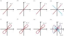
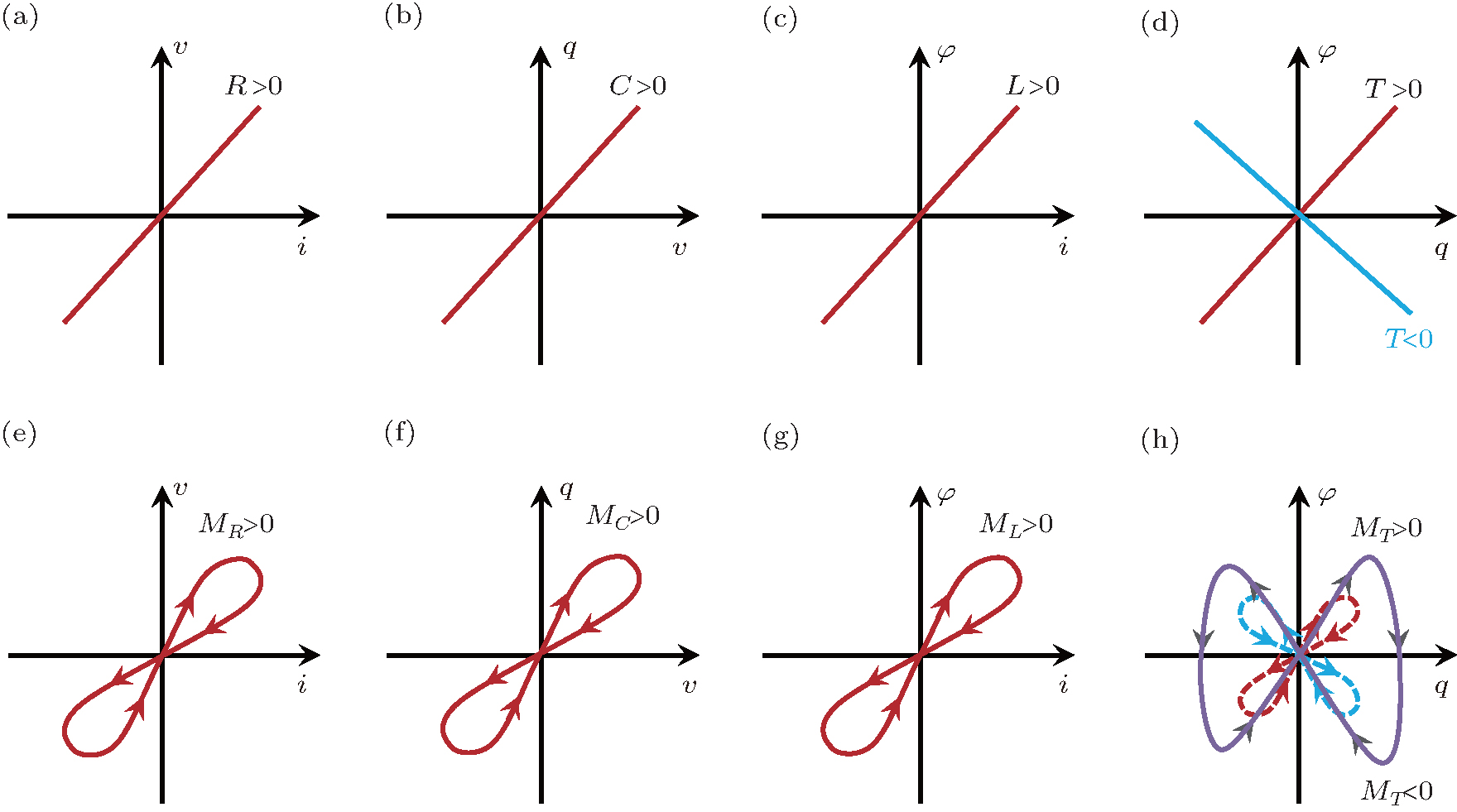 | Fig. 3. Schematic illustration of the linear and memristive-like behaviors for all the four fundamental circuit elements. The linear relationships of the four basic circuit variables define (a) the resistance, R, (b) the capacitance, C, (c) the inductance, L, and (d) the transtance, T, with only the transtance T being both positive and negative. Accordingly, (e) the memristance, MR, (f) the memcapacitance, MC, (g) meminductance, ML, and (h) the memtranstance, MT, are defined by pinched loops of the basic circuit variables. For MT, the butterfly-shaped loop in panel (h) occurs at a sufficiently large input of q. |
To make use of the transtor in an electric circuit, it can be coupled with an inductor via a circular magnetic core with infinite permeability μ to form a well-known four-terminal electric network element, a gyrator, as shown in Fig. 2(c).[24] As clearly pointed out by Tellegen[24] and demonstrated by Zhai et al., [25] a gyrator is also a linear, passive network element which has peculiar anti-reciprocal relationships: v1 = − gi2, v2 = gi1, where g is a constant gyrator coefficient (in ohms), v1, i1 and v2, i2 are the voltage and current from the transtor and inductor, respectively. This also proves that the transtor is an independent circuit element that cannot be replaced by a network composed of the other three linear two-terminal elements. Notably, however, the ME component in the gyrator has never been discussed in the context of the fourth linear circuit element. Moreover, we propose that one transtor can also be similarly coupled with another transtor to form a new type of four-terminal electric network element, as shown in Fig. 2(d). In this case,


where i1, T1 and i2, T2 are the current and transtance from the first and second transtors, respectively. Therefore, it can be regarded as a current converter.
In analogy to the memory counterparts of other fundamental circuit elements, namely, the memcapacitor (MC) and meminductor (ML), the memristor should be treated as the memory counterpart of the resistor (Fig. 1(b)), to be consistent with the convention. Thus, it is appropriate to adopt MR to replace the original symbol M. In the place of M in Fig. 1(a), we introduced the symbol T to linearly relate φ and q. The memory counterpart of transtor, dubbed memtranstor, is denoted as MT.
Very similar to the memristive system, [2, 15] a charge-driven memtranstor can be defined by


where x can be a set of state variables and f is a continuous vector function. In a simplified case, equations (19) and (20) are reduced to

Similarly, a flux-driven memtranstor is defined by

The typical behavior of the memristor, described by similar equations, is characterized by a “ pinched hysteretic loop” dwelling in the I and III quadrants due to the uniquely positive value of MR (Fig. 3(e)). This is also true for the memcapacitor and meminductor (Figs. 3(f) and 3(g)). It is reasonable to expect that for a periodic charge/flux input, the memtranstor should also show a pinched hysteretic loop. However, MT will certainly manifest a distinctive memory behavior as transtance can be both positive and negative (Fig. 3(d)). Consequently, the memory behaviors of a memtranstor should be more interesting. As we postulate in Fig. 3(h), the pinched hysteretic loop can lie either in the I and III quadrants or in the II and IV quadrants. Moreover, we propose that a unique butterfly-shaped pinched loop is anticipated by virtue of the sign of MT changing when a sufficiently large input of charge or flux is supplied (see Fig. 3(h)). The memtranstor can also be used in the gyrator and the current converter shown in Figs. 2(c) and 2(d) by replacing the transtors to have versatile memory functionalities.
In summary, the true fourth fundamental linear circuit element, the transtor (T), and its memory element, the memtranstor (MT), can be realized by employing ME effects. With these newly defined elements, we are able to construct a complete and harmonized fundamental circuit relational graph, which consists of four linear (R, C, L, T) and four memory (MR, MC, ML, MT) elements, as shown in Fig. 1(b). The complete relational graph for fundamental circuit elements can provide a new guide to circuit functionality. As the transtance and the memtranstance can both be either positive or negative, the possibilities of their implementations are greatly extended. For hundreds of years, circuit functionalities have been dominated by the regime of three linear elements. Memory elements such as memresistor are attracting more attention because they enable more advanced circuit functions. In the future, the complete regime of this relational graph should be fully exploited and utilized to broaden circuit functionality for next-generation intelligent devices.
We thank S. H. Chun and K. H. Kim for their help in discussion and figure painting.
| 1 |
|
| 2 |
|
| 3 |
|
| 4 |
|
| 5 |
|
| 6 |
|
| 7 |
|
| 8 |
|
| 9 |
|
| 10 |
|
| 11 |
|
| 12 |
|
| 13 |
|
| 14 |
|
| 15 |
|
| 16 |
|
| 17 |
|
| 18 |
|
| 19 |
|
| 20 |
|
| 21 |
|
| 22 |
|
| 23 |
|
| 24 |
|
| 25 |
|