


Generic meminductive characteristics of switched reluctance machines*
[Liang Yan, Chen Hao† , Liu Hua-Jian, Shi Jiao-Tong]
, Liu Hua-Jian, Shi Jiao-Tong]
|
|


†Corresponding author. E-mail: chenhaocumt@tom.com
*Project supported by the National Natural Science Foundation of China (Grant No. 51277174), the Specialized Research Fund for the Doctoral Program of Higher Education of China (Grant No. 20120095110019), a Project Funded by the Priority Academic Program Development of Jiangsu Higher Education Institutions, and the Research and Innovation Program of Postgraduates of Jiangsu Province, China (Grant No. KYLX_1382).
The meminductive system can be regarded as the generalization of the meminductor. This paper focuses on exploring the generic meminductive characteristics of the switched reluctance machine (SRM). The dynamical equations of SRM systems are derived and discussed in comparison with the typical constitutive relation equations of the meminductive system. Memory ability and pinched hysteresis loop (PHL) are taken as the indicative fingerprints to draw forth the theoretically comparative analysis. Based on the theoretical analysis, in addition to simulation and experimental confirmation, it can be concluded that from the viewpoint of circuit, SRM can be considered as a generic meminductive system.
Since the physical nano-scale TiO2 device behaving as a memristor was reported by the HP Laboratory, tremendous research interest has been aroused to further discover the unique properties and potential applications of memristors.[1] Memristor, characterized by the relationship between charge and flux, was first predicted by Chua in 1971.[2] The notion of the memristor was then extended to a memristive system where the flux no longer simply depends on the charge.[3] Memristive behaviors have been observed in many dynamic systems, such as thermistors, nanoscale systems, spintronic devices, etc.[4– 8] Typical memristive fingerprints observed from discharge lamps have been reported in Ref. [7], where the discharge lamps are defined as not ideal but volatile memristors.
In 2009, Ventra et al. put forward the definitions of memcapacitive and meminductive systems, as well as their subclass elements, namely the memcapacitor and meminductor.[9] Memcapacitors and meminductors have the ability to store information in the electric and magnetic field, which can open up new application realms in the energy storage and transmission. With respect to meminductor, there are only a few articles related to simulation models and circuit emulators.[10– 13] Although the research concentrating on the meminductor is less than on the memristor and memcapacitor, hysteretic characteristics of iron-cored inductor have been discovered in Ref. [14]. Furthermore, reference [15] overviews the experimental realizations of meminductive system and speculates meminductive behavior may exist in the ferromagnetic material. Switched reluctance machines (SRMs) are comprised of coiled stator poles and rotor without coils, wherein stator and rotor are both made of magnetic material (silicon steel sheet). The inductance of each phase winding is determined by the current with regard to a specific SRM rotor position. Inspired by these inherent properties, in this paper, we focus on extracting the generic meminductive characteristics of SRMs. SRMs have been widely utilized in many cases such as electric vehicle, power generator, aircraft starter/generator, etc., owing to its simple structure, wide speed range, inherent fault-tolerance, and high operating efficiency.[16, 17] Investigation on the inherent circuit characteristics could provide further contributions to thoroughly analyzing and improving the operation performances of SRM systems.
The rest of this paper is organized as follows. In Section 2, the constitutive equations and fingerprints of meminductive systems, as well as the possible implementations of variable inductance are introduced. In Section 3, the modeling and mathematical representations of SRMs are described. In Section 4, the generic meminductive characteristics of single-phase alternating current (AC) SR generator (SRG) are presented. The meminductive characteristics existing in the motoring mode are theoretically analyzed and experimentally testified in Section 5. A brief conclusion is given in Section 6.
By defining two constitutive circuit variables u(t) and y(t) as the input and output of a dynamic system, a u-controlled memory element can be written as[9]
where x is the internal state variable, g denotes a generalized response, and fm is a continuous function.
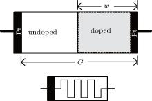
HP memristor, a passive nano-scale device, is regarded as an ideal memristor. This memristive device can be divided into undoped and doped layers, as shown in Fig. 1, where an undoped titanium dioxide layer with much lower resistance Ron and a doped titanium dioxide layer with high resistance Roff, connected together on a nano-scale, are sandwiched by two platinum contacts. Assuming that G represents the total length of the two layers and w denotes the width of the doped region, in accordance with the mathematic description given by the HP Laboratory, the memristance RM can be mathematically presented by

Corresponding to the function fm from Eq. (1), w is regarded as the internal state variable of the HP memristor and can be depicted as a function of charge q, [1] namely,

where w0 is the initial size of the doped region and uv is the average dopant mobility. As stressed in Ref. [1], the value of state variable w has a restricted range of [0, G].
 | Fig. 1. Structure diagram of HP memristor. |
Equation (1) can also be used to present a general meminductive system, by defining two constitutive circuit variables as flux linkage and current, respectively. With regard to the HP memristor, an internal variable w is adopted to describe the controllable memristance. Hence, it can be speculated that there must be an internal variable w of the meminductor, also restricted in the range of [0, G], which can be used for describing the meminductance. Many memristor emulators have been proposed.[18– 21] Most of them are based on the devices with changeable resistance.[20, 21] Likewise, the meminductive system can also originate from the devices with variable inductance.
In consideration of a regular inductor, the inductance can be depicted by

where N denotes the number of inductor turns; . Rm is the reluctance and Rm = l0/(μ A); l0, μ , and A denote the length of circuit, permeability, and cross-section area of the coil respectively. Equation (4) indicates that the inductance can be varied by modifying turn number N or reluctance Rm. For instance, a slider with two terminals can be used to change the number of operated turns N of the air coil inductors and hence result in different inductance values. Based on variation of turns, an SPICE model has been proposed to mimic a meminductor in Ref. [10] as shown in Fig. 2(a). It can be observed that the state variable w is proportional to the number of turns, since the coils are uniformly wound on a nonmagnetic material. Moreover, the differential of w with respect to time t is a function of current. For this specific meminductor, the width of the internal variable w is in fact equal to wmax – wmin, which is determined by the geometric structure of coils.
 | Fig. 2. Structure diagrams of variable inductors. |
The reluctance of an inductor with moveable ferrite magnetic core can be varied by changing the core position as depicted in Fig. 2(b). In this case, the state variable w can be introduced to denote the displacement between the left sides of the magnetic core and coils. Assuming that the time differential of w is controlled by current or flux, a memindutor can be obtained, where the range of state variable w is restricted in the interval of [0, G]. In consideration of different inductance by means of varying reluctance, additional current bias can be used to change the permeability of a saturable material.
Meminductive system, whose inductance depends on the historical variables, can store inductive information and the magnetic energy. Essentially, as a member of the memory element family, the meminductive system shares similar properties to the memristive system, such as memory ability and a pinched hysteresis loop (PHL).
The operation of SRMs is based on the variation of magnetic reluctance which is aroused by a moveable rotor. Due to the doubly salient pole structure and deep saturation characteristics, the value of phase inductance is dependent on the current and rotor position. SRM can be classified into single-phase, two-phase, and multiphase machine according to phase number.
Single-phase SRM has the simplest structure. However, due to the disadvantages of low power density and lack of self-starting, they are seldom operated as driving motors.[22] Here, single-phase SRM is operated as an autonomous AC SR generator (SRG) to analyze the steady behaviors in detail.[23] Since meminductor is defined as an analog element, in order to better comparatively analyze the meminductive behaviors, the output voltage and current waveforms of AC SRG are produced by the LC oscillation without any switching element.
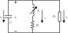
Inductance existing in SRM windings can be classified into self-inductance and mutual inductance. Since the mutual inductance is very small in comparison to self-inductance, the effect of mutual coupling can be neglected. A single-phase AC SRG is used to illustrate the operation principle as shown in Fig. 3 where C is the external capacitor. We can see that the autonomous AC SRG is operated similarly to an electronic oscillator. Considering neither the load RL nor small phase resistance RS, the oscillation frequency can be approximated by

where Lave is the average value of phase inductance.
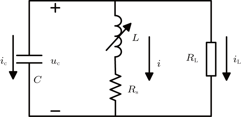 | Fig. 3. Equivalent circuit of single-phase AC SRG.[23] |
The typical LC oscillators are mainly structured on the basis of constant reactive circuit elements and an active element with positive feedback. As a result of the nonlinear phase inductance, the AC SRG can be considered as a parametric oscillator with the changeable parameter L. Equation (5) can be used to approximately evaluate the parallel capacitance, even though L is inconstant during oscillation.
The set of system equations can be given by[23]
where uc, i, ψ , and Rs denote phase voltage, phase current, phase flux linkage, and phase resistance, respectively; θ is the rotor position.
It is worth noting that single-phase AC SRG only represents a special case of SRM systems. In order to generally evaluate the meminductive behavior of single-phase AC SRG, mathematical representations and accurate simulation model are imperatively deduced beforehand. The simulation model is mainly based on the flux linkage or inductance characteristics. Owing to the periodicity of inductance variation, Fourier series can be utilized to express the inductance with regard to rotor position.
Since multiphase SRM system has been widely used in practice, four-phase 8/6 SRM is adopted for illustrating. In Ref. [24], only the first three terms of the Fourier series are considered. The inductance can be more accurately described by adding two extra high order terms as
where Nr is the number of rotor poles, and ck(i) is the coefficient of each term which can be represented by sixth-order polynomials. ck(i) can be calculated based on inductance at five critical rotor positions. In consideration of four-phase 8/6 SRM, these five positions can be selected as 0, π /24, π /12, π /8, and π /6, respectively, on the assumption that 0° corresponds to the position of the rotor unaligned with the stator. Due to the directly immeasurable inductance, the inductance data are derived based on the sampled flux linkage data with regard to these five positions.
Based on the analytical expression (7), the incremental inductance l(θ , i) is represented by
where dk = ck (i = 0). From Eq. (8) we can see that ∂ ψ /∂ i| i= 0 is dependent on rotor position. Since the analytical solution of the rotor position can hardly be analytically solved, numerical methods are used to obtain the solution of rotor position in the next section.
According to Eq. (7), the corresponding phase torque can be analytically expressed as

where Wc denotes co-energy. The electromechanical interactions of the SRM system can be given by

where J is the inertia, D is the viscose coefficient, and ω is the rotor angular velocity equivalent to dθ /dt. When the SRM works as a motor, the sign on the left-hand side of the bracket is positive and T denotes load torque. In the case of power generation, the sign outside the bracket is negative and T denotes the drag torque provided by the prime motor.
Note that the multiphase inductance model obtained above possesses higher universality and the model of each phase can be used to simulate the dynamics of single-phase AC SRG. Based on the analytical model equations and physical model of SRM, the dynamical equations of this system can be represented as

It can be observed from Eq. (11) that the phase flux linkage is zero, whenever the phase current is zero, regardless of the rotor position. This zero-crossing property asserts that the flux linkage and current locus always simultaneously pass through the origin. The internal state variable θ describes the rotor displacement with respect to the stator, which is similar to the case of a moveable magnetic core. The variation range of θ is determined by the rotor pole pitch of the SRM. For four-phase 8/6 SRM, the length G is fixed at 60° and θ can vary between 0° and 60° . Equation (11) indicates that the set of equations for describing the dynamics of SRM is in high similarity to the constitutive relation of meminductive system.
For a linear inductor element, the flux linkage versus current locus behaves as a straight line segment crossing the origin point. Differently, the phase inductance of SRM is dependent on phase current and rotor position.
According to the proposed mathematical representation (7), the inductance and flux linkage with respect to an arbitrary current and rotor position can be calculated. The magnetization curves are shown in Fig. 4. The surface represents the flux linkage versus position and current for one phase from 0° to 60° under the condition of amplitude of current up to 10 A. It can be seen from Fig. 4 that the magnetization curves are approximate to straight lines when – 4 A < i < 4 A. As the amplitude of current increases, the magnetic circuit steps into deeper saturation.
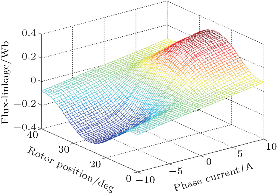 | Fig. 4. 3D plot of bipolar flux linkage against phase current and rotor position. |
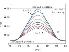
Figure 5 shows the variations of phase inductance in one electrical cycle. It can be seen that the maximum inductance of 78.5 mH can be achieved with the lowest current at the aligned position. When the rotor is located at an unaligned position, the phase inductance reaches its minimum value of 7 mH.
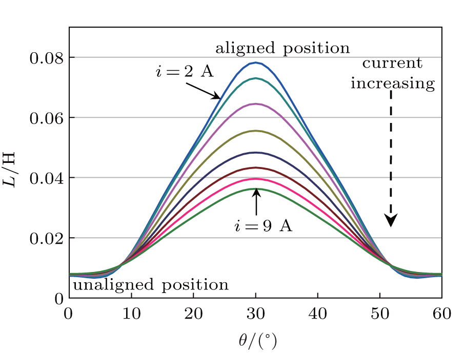 | Fig. 5. Variations of phase inductance versus rotor position for different currents. |
A unique property shared by memory elements is the PHL in the first quadrant and the third quadrant. The PHL of the memristor, as well as the meminductive system, can be classified into two types according to whether the loop is transversal or not at the origin.[25]
To draw the PHL, bipolar AC voltage or current is usually applied for exciting the memory elements. Generally, the SRM is operated for motoring or generating, with unipolar current flowing through each phase. In order to carry out better comparative analysis, phase A of the four-phase SRM is selected and used for simulating the single-phase AC SRG. Here, the parallel capacitance is 940 μ F. The oscillation is achieved when the machine operates between 564 r/min and 580 r/min.
Based on the flux linkage characteristics of Fig. 4, the simulation model of single-phase AC SRG is implemented by Matlab/Simulink. Figure 6 shows the waveforms of phase current, flux linkage, phase inductance, capacitor voltage, and rotor position, with the configuration parameters of phase resistance and rotor speed equaling 1.55 Ω and 573 r/min, respectively. The inductance is obtained by the ratio of flux linkage to current.
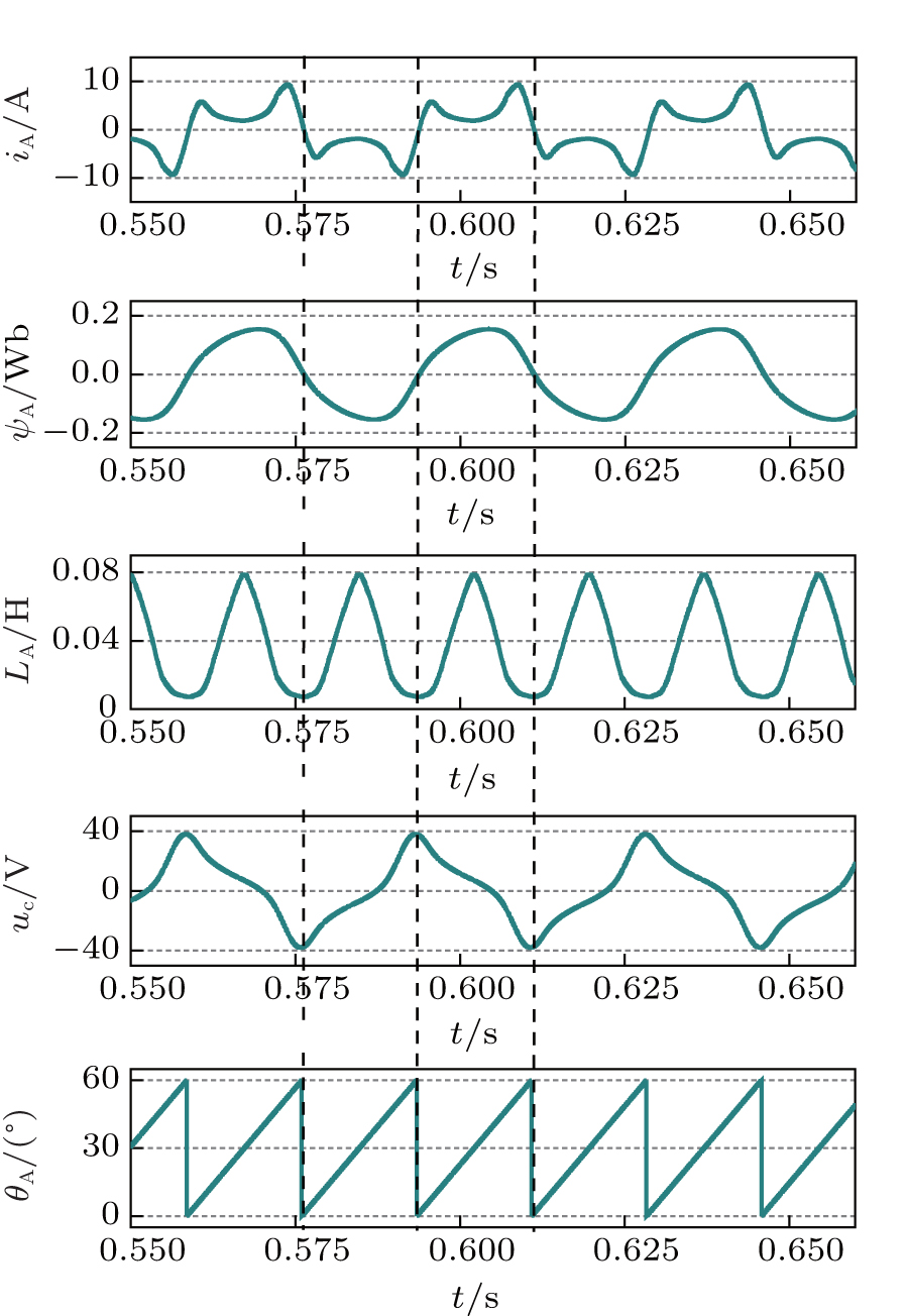 | Fig. 6. Waveforms of phase current, flux linkage, phase inductance, capacitor voltage, and rotor position for the single-phase AC SRG at n = 573 r/min. |
Figure 6 reveals that the current is zero whenever the flux linkage is zero. Note that the frequency of phase current, flux linkage, and capacitor voltage each has half of phase inductance frequency and can be described as

where n denotes the rotor speed, n = ω × 60/2π .
Figure 6 also indicates that the phase inductance has a unique value at iA = 0, thereby resulting in a non-transversal PHL. Figure 7 shows the non-transversal PHL of the phase inductance, and the variation of inductance with respect to the current is given in Fig. 8. Note that the locus of flux linkage versus current has specific physical meaning, namely, an energy conversion loop. The area within the flux linkage versus the current locus in one cycle of current denotes the generated energy Wloop.
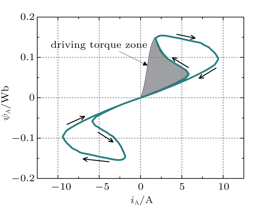 | Fig. 7. Plot of flux linkage versus current for the single-phase AC SRG at n = 573 r/min. |
 | Fig. 8. Variation of the phase inductance with phase current. |
Due to the bipolar current, the plot of flux linkage versus current is in the form of a typical non-transversal PHL. Similarly, non-transversal PHL is observed in a generalized memristor.[26] The slope of PHL, when the locus approaches to and departs from the origin, is equal. Note that the plot of LA versus iA is axisymmetrical with respect to the line at iA = 0.
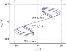
Another unique property shared by the meminductor is the frequency or amplitude dependence of the PHL. Generally, these characteristics are observed under the bipolar periodic input signal. Considering the fact that the operation of single-phase AC SRG is only valid within a rather small speed range, the frequency dependence of the PHL is hard to observe. However, a small change of oscillation frequency may cause variable phase voltage amplitude. The plots of flux linkage versus current locus at different rotor speeds, i.e., n = 568 r/min, 573 r/min, and 578 r/min, are shown in Fig. 9. The detailed simulation results at different rotor speeds are listed in Table 1.
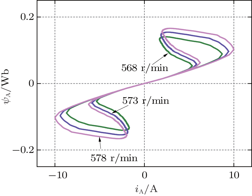 | Fig. 9. Flux linkage/current loci of single-phase AC SRG for different rotor speeds. |
| Table 1. Simulation results for single-phase AC SRG. |
Table 1 indicates that there is a little variation in frequency, but a relatively large change generating in phase voltage maximum value ucm for different rotor speeds. Here, the amplitude dependency of PHL dominates. Figure 9 shows that the maximum flux linkage ψ Ap and maximum current IAp both increase with rotor speed augment. The oscillation frequency influences the output voltage, i.e., the phase voltage. Based on Eq. (6), the increase of phase voltage will lead to higher flux linkage and higher current. Evidently, the area enclosed by PHL Wloop increases with the phase voltage amplitude augment, which is consistent with the theoretical analysis. The simulation results indicate the amplitude-dependent characteristic of PHL for AC SRG.
It can be observed that the capacitor voltage, i.e., the output voltage in Fig. 6 is non-sinusoidal. The voltage distortion can be attributed to the nonlinear characteristics of SRM phase inductance. This voltage is unsuitable for grid connection due to its high harmonic components. For conventional SRG, one of the main advantages is its wide adjustable speed range. However, the operation principle of single-phase AC SRG brings a limitation to the speed range. In the generating mode, the rising inductance yields the driving torque. The produced driving torque reduces the energy generation as shown in Fig. 7. It can be observed that the efficiency of AC SRG is lower without control switches than that of a traditional SRG.
The generic meminductive characteristics of the single-phase AC SRG have been identified in the previous section. Then in this section, we focus on the meminductive behavior of the widely used SR motor. The directions of SRM torque and speed are independent of the direction of the phase current, which differs from the conventional AC or direct current (DC) machine. Hence, an asymmetry half-bridge inverter is usually used to generate energy and unipolar currents in an experimental prototype system, where each phase contains two transistors and two diodes.[27]
The operational mode of SRM, either at motoring mode or at generating mode, is simultaneously determined by the turn-on angle and the turn-off angle. Here, the motoring operation is taken as an example for illustrating the memory ability. Each phase winding of SRM is powered in turn and the sequence of powered phase winding determines the spanning direction of the rotor. During steady state, the phase inductance is a periodic function of phase current and rotor position. If DC supply voltage is cut off, the speed will reduce to zero after a while. When the speed and phase current are equal to zero, the phase inductance of the SR motor will be frozen there, until we reset the inductance by reapplying the excitation voltage. This unique characteristic of SR motor phase inductance can be regarded as the memory ability.
In order to observe the memory ability, a four-phase 8/6 SRM system is built up. The parameters are initialized as follows: load torque Tload = 0.47 N· m, turn-on angle θ on = 0° , and turn-off angle θ off = 30° . For simplicity, the SRM is operated at speed open-loop mode with the current chopped control strategy. The current chopped control is used to prevent the transistors from being destroyed by high current at low rotor speed. The experimental measurements and simulations are carried out to observe the operation appearance. A square wave voltage (amplitude US = 24 V, and period T = 2 s) instead of DC voltage is utilized as the supply source. The experiment data are captured by an oscilloscope TDS2014 and drawn by Origin 8.0.
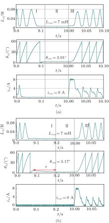
Figure 10 depicts the waveforms of phase inductance, rotor position, and current for phase A. Since inductance cannot be derived when i = 0 based on the ratio between flux linkage and current, the proposed analytical expression (7) is used to obtain the inductance curve based on the measured current and rotor position. The whole process is divided into three regions, i.e., region I, region II, and region III as shown in Fig. 10.
Region I shows several electrical cycles after the supply voltage is switched off. The current drops down rapidly through the freewheel diodes. When the current is zero, the inductance simply varies with rotor position. The frequency of phase inductance and rotor position decreases as speed decreases. Note that there is a short process interval τ when the motor rotates inversely before it stops in the experiment; this is a small oscillation of the motor occurring in the switching state. In region II, the motor stops and speed is equal to zero. In other words, the rotor position and phase inductance are kept at constant values of θ con and Lcon. Thus, the phase winding can store the information in inductance form. The stator winding again is energized in region III, which results in the speed increasing. At the same time, rotor position starts to vary periodically and current rises rapidly since θ on < θ con < θ off. Furthermore, the inductance starts to periodically vary from the fixed value which is determined by historical dynamics.
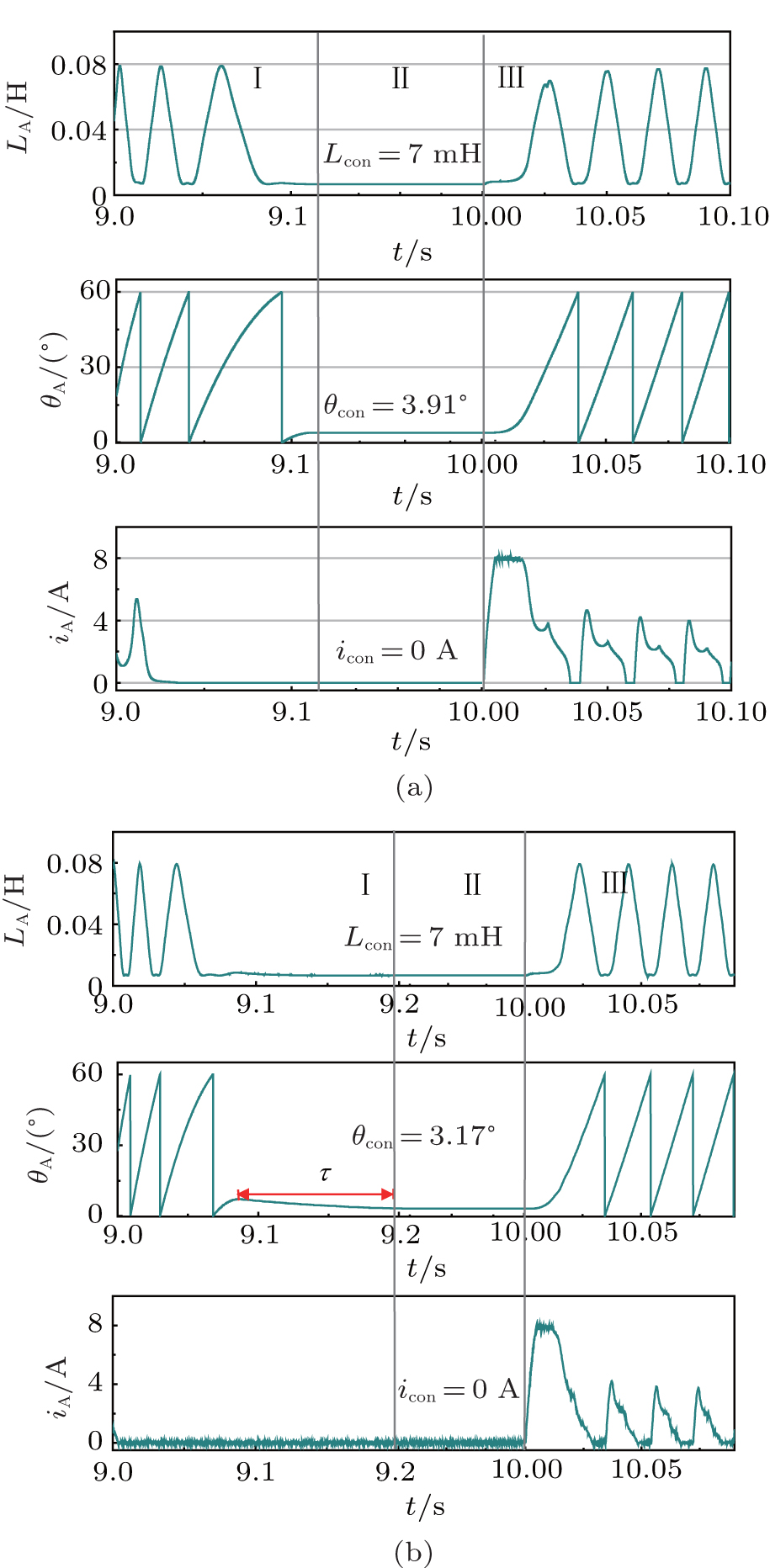 | Fig. 10. Waveforms of phase inductance, rotor position, and phase current: (a) simulation results, (b) experimental results. |
Based on the analyses of experimental and simulation results, we can observe that the SR motor exhibits memory ability. The instantaneous value of its inductance depends on the overall history of the system. This characteristic also holds for SRG.
Since the phase current and flux linkage of the SR motor are unipolar, the PHL only exists in the first quadrant. Here, analysis and experimental confirmation for the pinched hysteresis flux linkage versus current locus are presented in one stroke (one current pulse is called a stroke).
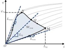
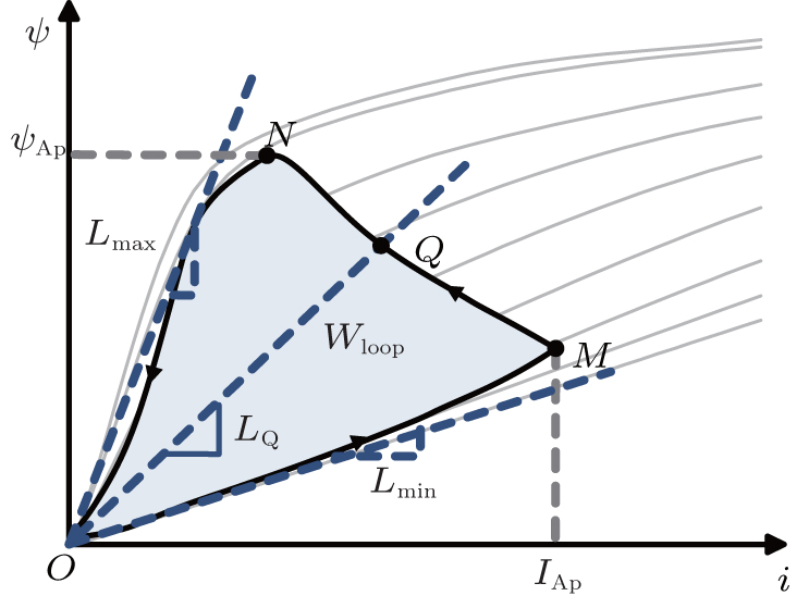
Figure 11 shows the energy conversion loop considered in the theoretical analysis during a motoring stroke. The flux linkage ψ and current i grow from zero and then fall to zero at the end of each stroke. Note that the maximum values of the flux linkage and phase current are not simultaneously present. In the operating process from point O to N passing through M, the driving transistors are conducted and the machine absorbs energy from supply power. At the point of M, the phase current reaches its maximum value IAp and then starts to decrease because of the rapidly rising inductance. However, the flux linkage keeps growing until approaching the turning point N. Point N corresponds to the turn-off angle, where the flux linkage reaches the maximum value ψ Ap. Afterwards the supply voltage is cut off and the stored magnetic energy is returned to the power supply. In one stroke, the output energy plus the energy returned to the supply is equal to the previously supplied energy. Hence, the characteristic of flux linkage versus current hysteresis presents the process of the energy conversion.
 | Fig. 11. Energy conversion loop of SR motor. |
For the SR motor, the area enclosed by the PHL corresponds to the energy converted to mechanical work during one stroke. Inversely, the area within the flux linkage versus current locus of the SRG denotes the energy that is electric energy converted from mechanical energy.
An arbitrary operation point Q is taken as an example for explanation. Based on the definition of an inductor, the inductance at this point can be calculated by the slope of the straight line OQ. The maximum and minimum slopes of the points on the loop are considered as the maximum and minimum value of the phase inductance as shown by the dashed lines in Fig. 11. Note that the dynamic loop is confined between the inductance extreme values for one stroke.
The average torque for an SRM can be expressed as

where mph is the number of phase. So the average torque can be related to the flux linkage versus current locus area. According to the principle of electromagnetic energy conversion, the co-energy in each stroke for different dwellings must be equal to the load torque.
The fundamental frequency f of voltage across the phase winding or the current in each phase is affected by the speed of the machine, and f is given by

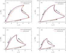
The speed will vary with the load torque in the case of speed open-loop operation. Based on Eqs. (13) and (14), the enclosed area of the energy conversion loop of the SRM is related to the frequency of the phase current. Here, the speed open-loop operation and current chopped control are adopted. Practical tests and simulations on the four-phase 8/6 prototype have been used to obtain the flux linkage– current characteristics for different frequencies. The rated voltage applied to each phase winding is 24 V and the rated current is 8 A. The turn-on and turn-off angles are configured as θ on = 0° and θ off = 24° . Based on the measured phase voltage and phase current waveforms, experimental flux linkage waveforms can be calculated using Eq. (6). Figure 12 shows the experimental and simulated results of energy-conversion loops at different load torques, i.e., 4 Nm, 3 Nm, 2 Nm, and 1 Nm corresponding to the speeds of 169 r/min, 243 r/min, 318 r/min, and 485 r/min, respectively. The experimental measurement results are listed in Table 2. Figure 12 shows that the rotor speed increases as the decrease of the load torque. Hence, the enclosed area of the PHL indeed is related to frequency. The experimental and simulated results are both consistent with the theoretical analysis. Furthermore, the maximum values of flux linkage and current increase with frequency.
| Table 2. Experimental results for multiphase SR motor. |
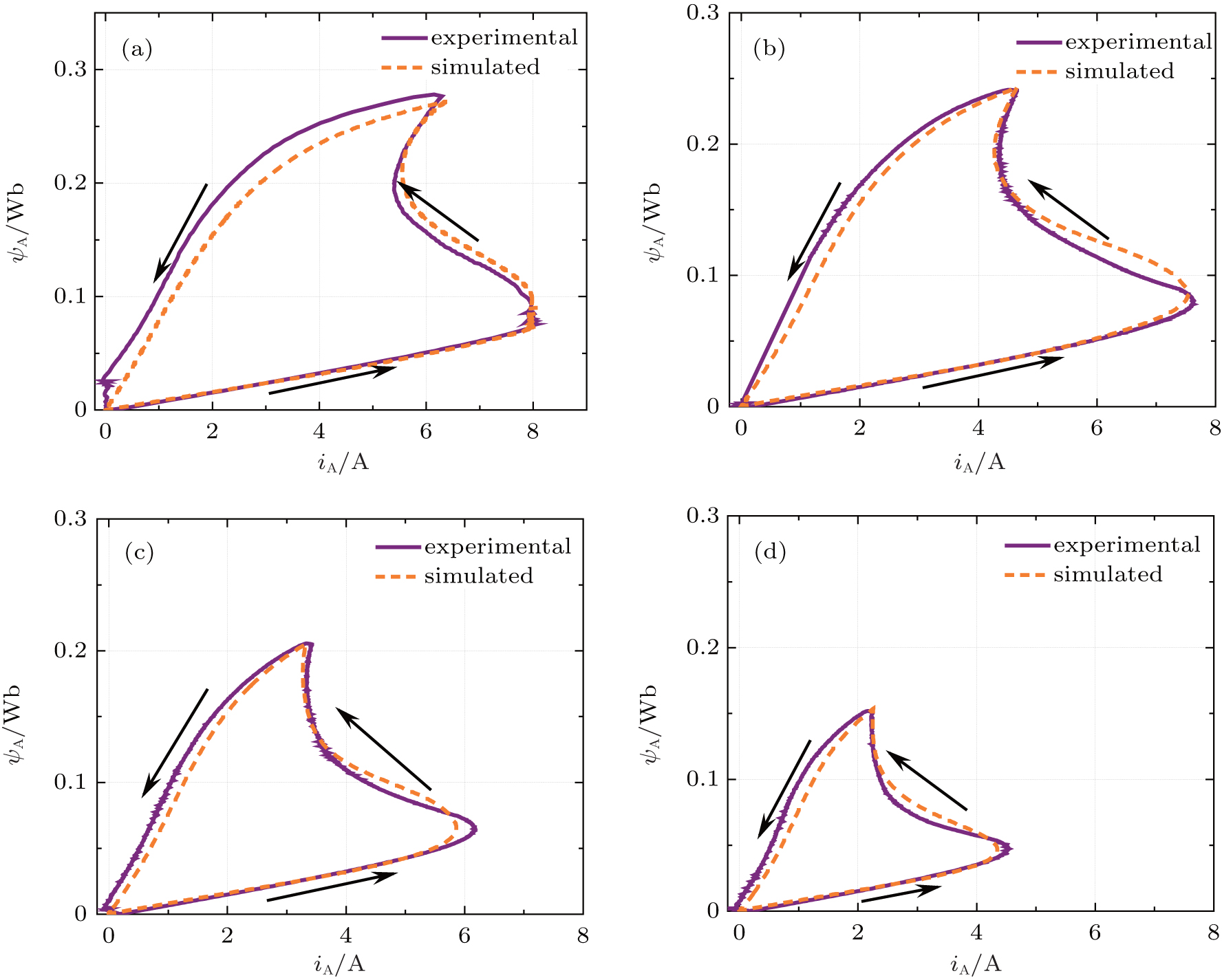 | Fig. 12. Flux linkage-current characteristics of SR motor for different frequencies, i.e., (a) f = 16.9 Hz, (b) f = 24.3 Hz, (c) f = 31.8 Hz, and (d) f = 48.5 Hz. |
Note that when f = 16.9 Hz, the current is limited at 8 A to protect the transistors. Taking f = 24.3 Hz for example, the time-domain experimental waveforms of phase voltage, phase current, and phase flux linkage are shown in Fig. 13. There are several features exhibited in Fig. 12 and Table 2 requiring attention. First, the flux linkage versus current locus in one stroke of the SR motor exhibits PHL. Second, the area enclosed by the loop, i.e., the co-energy, decreases as the frequency of current increases. This is because the higher speed will lead to the lower electrical torque, which is the mechanical property of SRM.
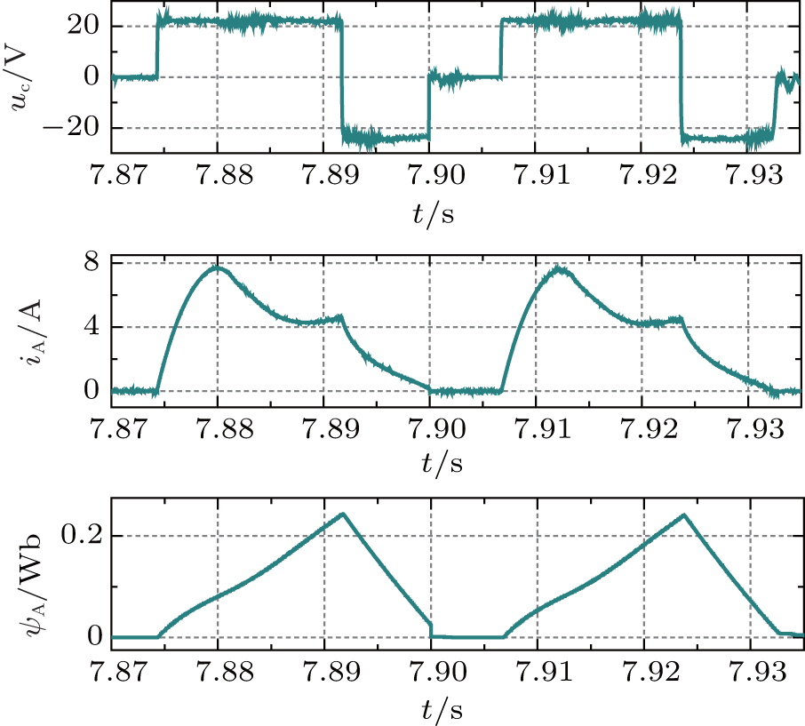 | Fig. 13. Experimental waveforms of phase voltage, phase current, and flux linkage when f = 24.3 Hz. |
More experimental data are captured to elucidate the variation of PHL area over a wide frequency range as shown in Fig. 14. The maximum rotor speed is determined by the inherent properties of a special SRM. Very low speed will produce much torque ripple. Due to the restrictions of machine material and supply voltage, the case of infinite frequency cannot be discussed. However, we can observe that the PHL area is approximately zero when the frequency is above 120 Hz. The good agreement between the simulation and the experimental results validates the above theoretical analysis.
 | Fig. 14. Variation of area of the PHL with frequency. |
Based on the mathematical model and the inductance profile, the phase winding of the SRM can be regarded as a nonlinear inductor whose inductance can be varied by rotor position and current. The generic meminductive characteristics existing in single-phase AC SRG have been theoretically analyzed and verified by the simulation model. The memory ability of phase inductance and behavior of hysteresis flux linkage versus current are observed in a practical multiphase SR motor system. The simulation and experimental results manifest that the SRM has a strong resemblance to the meminductive system. The analysis and confirmation of meminductive behaviors existing in SRM systems will provide a meaningful guidance for engineers on modeling, controlling, and optimizing the SRM system.
| 1 |
|
| 2 |
|
| 3 |
|
| 4 |
|
| 5 |
|
| 6 |
|
| 7 |
|
| 8 |
|
| 9 |
|
| 10 |
|
| 11 |
|
| 12 |
|
| 13 |
|
| 14 |
|
| 15 |
|
| 16 |
|
| 17 |
|
| 18 |
|
| 19 |
|
| 20 |
|
| 21 |
|
| 22 |
|
| 23 |
|
| 24 |
|
| 25 |
|
| 26 |
|
| 27 |
|