
Giant enhancement of Kerr rotation in two-dimensional Bismuth iron garnet/Ag photonic crystals*
[Liang Honga), b) , Liu Huanc) , Zhang Qianga), c) , Fu Shu-Fangc)†  , Zhou Sheng
c) , Wang Xuan-Zhangc) ]
, Zhou Sheng|
|


†Corresponding author. E-mail: shufangfu1975@163.com
*Project supported by the National Natural Science Foundation of China (Grant Nos. 11104050, 10947168, 11204056, and 11304068).
Kerr effects of two-dimensional (2D) Bismuth iron garnet (BIG)/Ag photonic crystals (PCs) combined magnetic and plasmonic functionalities is investigated with the effective medium theory. An analytical expression of Kerr rotation angles is derived, in which the effects of the surface pasmons polaritons (SPP) on magneto–optical (MO) activities are reflected. The largest enhancement of Kerr rotation up to now is demonstrated, which is improved three orders of magnitude compared with that of BIG film. When λ < 750 nm all of the reflection are over 10% for the arbitrary filling ratio f1, in addition, the enhancement of Kerr rotation angles are at least one order of magnitude.
Magnetic field-induced modifications of the optical properties of materials were first observed by Faraday[1] and Kerr.[2, 3] They detected a change in the polarization state of the transmitted (Faraday effect) or reflected light (Kerr effect) when a magnetic field was applied to a glass or to a ferromagnetic metal, respectively. Since then, magneto– optical (MO) activities have played a relevant technological role in different areas. Nowadays, many studies have been focused on the development of materials with large MO activity to improve the performance of the optical devices and expand the applications. One way to enhance the MO response is magnetophotonic crystals (MPCs), in which PCs are fabricated from transparent magnetic materials.[4] Practical realization of magnetophotonic devices based on MPCs requires magnetic materials with low absorption that ensures considerable photonic-band gap effect. However, most magnetic materials with high magnetic responses are metals with large absorption in visible and near infrared spectra regions. On the other hand, the surface plasmon-polaritons (SPPs) in metals can be excited, which can localize light and alter the field distribution at sub-wavelength scale.[5– 8] SPP resonances could play a key role in enhancing the MO response. Therefore, combing SPPs with MO is of particular interest, as it can lead to the observation of new optical phenomena such as enhanced optical transmission, sub-wavelength confinement of optical fields, and sub-wavelength optical resolution.[9– 14]
Strong modification of MO response near plasmonic resonances was discussed theoretically in Ref. [15]. Belotelov et al. substituted the ferromagnetic materials (FM) with a low-absorptive noble metal and a magneto– optical dielectric layer. As a result, a large enhancement of the transverse magneto– optical Kerr effect (TMOKE) was produced and the transmitted light intensity could be modulated by 1.5%.[15– 17] In this structure, the SPPs are allowed to propagate at the magnetized surface. Kreilkamp et al. experimentally demonstrated the enhancement of TMOKE due to the interaction of particle plasmons in gold nanowires with a photonic waveguide consisting of MO material, where hybrid waveguide-plasmon polaritons are excited.[18] Besides one-way waveguiding and one-way extraordinary optical transmission were proposed by integrating magnetic materials with photonic crystals (PCs) and spoof plasmons.[19, 20] By fabricating plasmonic nanostructures on laser-deposited MO thin film, Chin et al. reported that Faraday rotation is enhanced by one order of magnitude while high transparency is maintained. The interplay between plasmons and different photonic waveguide modes in the system is introduced to elucidate the enhanced Faraday effect.[21] Based on these concepts, the design and tailoring of the optical properties of complex composite magnetic materials towards particular potential applications will become possible.
Since most magnetic materials of interest are metals that strongly absorb light, it is convenient to experimentally measure the reflected light in order to probe the magneto– optic effect. Therefore, in this paper both approaches of plasmonic and MPCs are combined for realization of a scheme of MOKE enhancement using resonant excitation of SPPs in two-dimensional (2D) Bismuth iron garnet (BIG)/Ag MPCs.
We consider such a 2D MPC constructed by periodically embedding cylinder nanowires into an FM with thickness d along the z axis, as shown in Fig. 1. The cylinder nanowires are aligned along the z axis of the Cartesian coordinate system. The metal filling ratio is defined as f2 = π R2/L2 where L and R indicate the lattice constant and cylindrical radius, respectively.[22] Thus, the FM filling ratio will be f1 = 1 − π R2/L2. The electromagnetic waves propagate along the z axis. In the presence of static magnetization which is parallel to the nanowires, the permittivity of FM can be described by the following tensor[10]

where g is the gyrotropy parameter proportional to the magnetization magnitude. The off-diagonal elements will give rise to an additional electric field component orthogonal to the electric field of the incident light. As a result, the polarized plane at the optical far-field will be rotated in order to satisfy the oscillation of the emitted secondary component of the electrical field. The Drude-model of the metal used in this paper is

where ω p is the plasma frequency and γ c is the collision frequency, respectively. This dielectric function takes into account the contribution of free electrons only and generally describes the bulk metal. In our case, according to the definition of the filling ratio, this structure is the bulk Ag when f1 = 0. With the increase in f1, the proportion of BIG also increases. Finally, it becomes BIG film when f1 = 1.0. Therefore, using this dielectric function we expect that maybe some interesting approximate results can be obtained.[23]
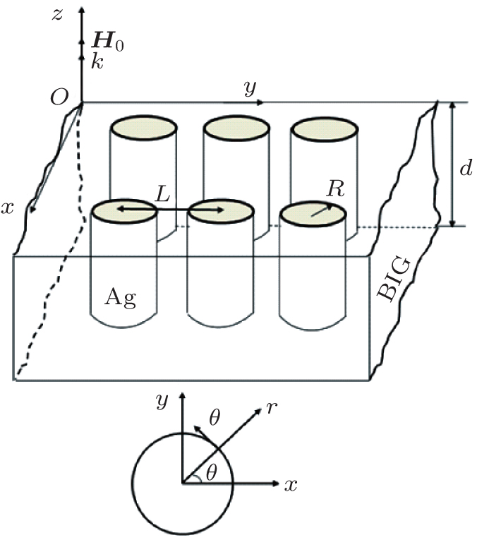 | Fig. 1. Geometry configuration and coordinate system. The external magnetic field and the BIG sublattice magnetizations are aligned along the z axis. The bottom one is offered to the coordinate transformation between the xyz and rθ z systems. |
When the MPC cell size is much shorter than the wavelength of electromagnetic wave, an effective-medium method can be established for one to obtain the effective permittivity of MPCs.[22, 24, 25] The nonzero elements for the effective dielectrics of MPCs is

where


with ε rr = ε θ θ = ε zz = ε , ε rθ = ig. The detailed derivation of the effective dielectrics are shown in Appendix A.
We subsequently derive the wave equations in the PC with the Maxwell’ s equations

with the electric displacement D = 𝜀 e · E and the magnetic induction B = H within the optical frequencies. Due to the fact that propagation is along the z axis, we assume that the wave electric field is E = Aeikz− iω t and find that


which lead to

The two equations generally correspond to positive and negative elliptically polarized waves, respectively. The effective permittivity is complex since the damping is added in their expressions, so k± are also complex. It is obvious that the attenuation occurs when the waves propagate in this PC. From Eq. (6), we find that 
In the following paragraph, the Kerr rotation of the MPC will be derived. We select a linearly-polarized incident wave with the electric amplitude parallel to the x direction. Thus the general wave solutions outside and inside the MPC can be expressed as


The magnetic field can be obtained from ∇ × E = − iω H. According to the boundary conditions, the relation between the output above the film and the amplitudes in FM layer is

with the matrix
with δ ± = k± /k0μ . Finally, the relation between the amplitudes in the FM layer and the transmission amplitude is

where
with γ ± = (1 ± δ + )/δ + and λ ± = (1± δ − )/δ − . After multiple reflections, there will be a reflected beam backscattered into the upper film and a transmitted beam that emerges from the bottom layer into the final medium. Thus, the matrix equation satisfied by the reflection, transmission and incident amplitudes can be obtained, which is presented as

Consequently, the Kerr rotation can be obtained by θ K = arc tan [Re(Ry/Rx)].
In numerical calculations, the ferromagnetic film is of BIG medium with the average values of ε = 6.7 + 0.053i and g = 0.016 − 0.0092i over the spectrum from 650 nm to 1050 nm.[18] The parameters of Ag are as follows: ω p = 1.5× 10¹⁶ rad/s, γ c = 7.73× 10¹³ rad/s, and ε ∞ = 6. The thickness of MPCs is d = 30 nm, which is much smaller than the wavelength.
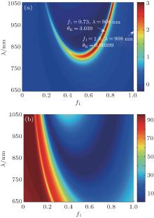
Figure 2 shows that the rotation angles and reflectivity change versus the wavelength λ and the filling ratio f1. An obvious enhancement of Kerr rotation angles occurs in the range of 0.2 < f1 < 0.8 when λ > 800 nm. The maximum Kerr rotation angle has been marked in the figure, which is about 3.039 near f1 = 0.73 and λ = 908 nm. It can be improved about three orders of magnitude in comparison with the single BIG film. The reflectivity of MPCs is shown in Fig. 2(b), which decreases with the increase in f1. It can be understood that most of light will be reflected by the metal in the smaller f1 and can transmit the MPC when the BIG is the main part. Comparing Fig. 2(a) with Fig. 2(b), we found that in the range of the larger Kerr rotation the reflectivity is relatively lower. Therefore, it is necessary to look for the scope where both the rotation angles and reflectivity are higher for potential applications.
 | Fig. 2. (a) Kerr rotation angles θ K change versus the wavelength λ and the filling ratio f1. (b) Reflectivity changes versus the wavelength λ and the filling ratio f1. |
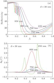
In Fig. 3, a group curves describe the Kerr rotation angles and reflectivity versus f1 at different wavelengths. The reflectivity over 10% is marked in Fig. 3(a) using a line. It can be seen that for λ < 750 nm the reflectivity curves are on the dash line in all the range of f1. However, for λ ≥ 750 nm, parts of the curves are below 10%, where the critical values of f1 can be demonstrated by the intersection of the dash line with the reflective curves for different wavelengths. In addition, the range of the critical f1 will become bigger versus the increasing wavelength. It can be found from Fig. 3(b) that the maximum of Kerr rotation angles is very higher for λ > 750 nm but the reflectivity is much lower. By comparing with Fig. 3(a), a conclusion can be made: the range which can be used in the application will be in 0.3 < f1 < 0.4. In the case of λ < 750 nm, the situation is relatively easy since the reflectivity will be higher in all the range of f1. Therefore, we should only consider the range for the higher Kerr rotation angles, which can be in a range of 0.5 < f1 < 0.7. Within these filling ratio ranges, the enhancement of Kerr rotation angles is at least one or two orders of magnitude. Of course, much higher enhancement can also be reached in the area out of the slash with the price of decreasing reflectivity.
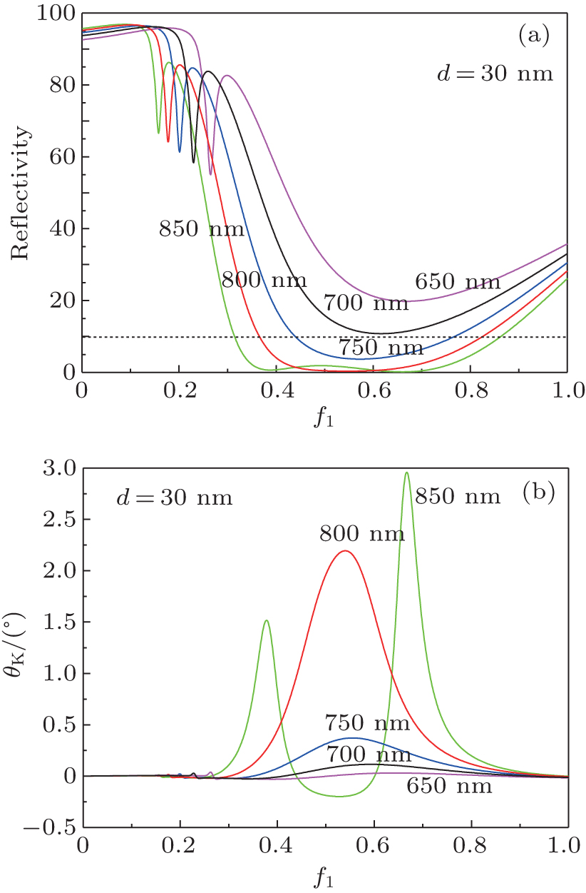 | Fig. 3. Group curves describe the reflectivity (a) and Kerr rotation (b) versus f1 at different wavelengths. |
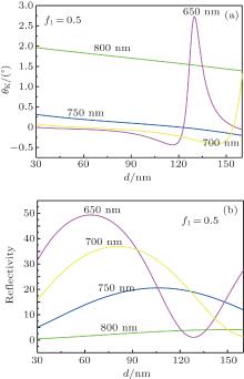
It is well known that the Kerr rotation is sensitive to the thickness of MPC due to the limitation of the light absorption. Figure 4 shows the Kerr rotation angles and reflectivity changing with the thickness of MPC at f1 = 0.5. In order to satisfy the requirement of the effective-medium method, here the thickest thickness of the BIG film is controlled at about one quarter of the shortest wavelength. For the longer wavelength Kerr rotation angles change slightly with the thickness. A highest peak appears at λ = 650 nm and d = 135 nm. The corresponding reflectivity versus the thickness is also shown in Fig. 4(b). Maybe the best thickness for different wavelengths can be expected by comparing Fig. 4(a) with Fig. 4(b).
 | Fig. 4. Kerr rotation (a) and reflectivity (b) change with the thickness of MPC at f1 = 0.5. |
In this paper, the Kerr effect of 2D BIG/Ag PCs has been discussed. An analytical expression of Kerr rotation angles is derived, where the effects of SPP and MO activities are combined. We have demonstrated the largest enhancement of Kerr rotation up to now, which is improved almost three orders of magnitude compared with that of BIG film. It can be imagined that when the light illuminates the sample, the coherent charge oscillations propagating along the cylindrical noble metal surface, namely, SPP, can be excited. Therefore, for the giant increasing of Kerr rotation angles, SPP should play an important role in the 2D BIG/Ag system.[26, 27] For the purpose of applications, a range, in which the reflection is over 10% and the Kerr rotation is improved at least one order, is defined for different wavelengths. It can be seen that for λ < 750 nm the filling ratio can be arbitrary since all of the reflection are over 10%. An optimum thickness is checked out for different wavelengths when f1 = 0.5.
The authors thank Drs. Liu Yong-Min and Yao Kan for useful discussion.
| 1 |
|
| 2 |
|
| 3 |
|
| 4 |
|
| 5 |
|
| 6 |
|
| 7 |
|
| 8 |
|
| 9 |
|
| 10 |
|
| 11 |
|
| 12 |
|
| 13 |
|
| 14 |
|
| 15 |
|
| 16 |
|
| 17 |
|
| 18 |
|
| 19 |
|
| 20 |
|
| 21 |
|
| 22 |
|
| 23 |
|
| 24 |
|
| 25 |
|
| 26 |
|
| 27 |
|