Evolution of magnetically rotating arc into large area arc plasma*
[Wang Chenga) , Li Wan-Wana) , Zhang Xiao-Ninga) , Zha Junb) , Xia Wei-Donga)†  ]
]
]
|
|


†Corresponding author. E-mail: xiawd@ustc.edu.cn
*Project supported by the National Natural Science Foundation of China (Grant Nos. 11035005, 11475174, and 50876101) and the Science Instrument Foundation of the Chinese Academy of Sciences (Grant No. Y201162).
An arc channel tends to shrink due to its conductivity increasing with the increase of temperature. In this study, to generate large area arc plasma, we construct a magnetically rotating arc plasma generator, which mainly consists of a lanthanide tungsten cathode (13 mm in diameter), a concentric cylindrical graphite anode chamber (60 mm in diameter) and a solenoid coil for producing an axial magnet field. By controlling the cold gas flow, the magnetically rotating arc evolves from constricted mode to diffuse mode, which almost fills the whole arc chamber cross section. Results show that the diffuse arc plasma has better uniformity and stability. The formation mechanism of large area arc plasma is discussed in this paper.
The arc plasma at atmospheric pressure is extremely heterogeneous, consisting of a highly luminous and constricted current channel. Thus, it is unsuitable for large-scale industrial applications, such as powder preparation, large area surface processing, chemical vapor reaction, etc.[1, 2] A variety of techniques, such as the dual-torch or triple-torch jet, hybrid plasma generator with inductively coupled plasma (ICP) and direct current (DC) arc, multi-electrodes with uniphase or multiphase alternating current (AC) power supplies, etc., have been developed to increase the arc plasma area and improve its uniformity.[3– 5] However, these techniques often require complex circuits or complicated operations, which severely restricts their industrial applications.
Several papers reported that a magnetically rotating arc may generate large area diffuse arc plasma at atmospheric pressure.[6– 14] However, the formation mechanism of this diffuse arc plasma is elusive. For instance, Mayo and Davis[15] reported that a diffuse arc plasma was observed in a magnetically rotating electric-arc air heater under an intense magnetic field (1 T to 2.5 T). Nevertheless, Harry and Guile[16] showed opposite results, in which the arc remained constricted in a similar device (up to 1.75-T magnetic field, 2100-A arc currents, and no inlet gas). They speculated that Mayo et al.’ s result about the diffuse arc plasma[15] might be a feint since the optical method was improper. Two other papers about diffuse arc plasma induced by a magnetic field were reported by Slinkman and Sacks, [6, 7] Xia et al., [8] and Li et al.[14] The cathodes and anodes in their plasma generators are all made of graphite. Their research showed that the arc gradually diffused with the increasing of arc current and axial magnetic field (AMF). The former inferred arc diffusing was governed by the uniform distributed cathodic arc roots. The formation mechanism is similar to that of the magnetic expanding arc at lower pressure.[17, 18] However, Xia et al.[8] proposed that the arc was spatially dispersed by convection with ambient cold gas, forming the so-called dispersed arc plasma (DAP). Nevertheless, there have been no experimental results to confirm either viewpoint.
In this study, we construct a magnetically rotating arc plasma generator to generate large area homogenous arc plasma. We test the effects of cold gas flow and cathodic arc root behaviors on the magnetically rotating arc evolution from constricted mode to diffuse mode. The formation mechanism of large area arc plasma is also discussed.
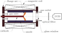
The experimental setup configuration is shown in Fig. 1. The arc plasma generator mainly consists of a cylindrical anode chamber (graphite, 60 mm in diameter, 200 mm in length) and a concentric lanthanide tungsten cathode (W– La alloy, 2%wt lanthana, 13 mm in diameter and 100 mm in length). A solenoid coil surrounding the generator produces a well-distributed AMF of a few hundred milli-Tesla in the chamber. One end of the chamber is covered with a cathode flange. Argon gas axially flows into the chamber through gas inlets distributed on the cathode flange. The other end is covered by a window flange with a glass, around which gas outlets are distributed uniformly. The generator is cooled by flowing water. A high-speed charge coupled device (CCD) camera (256× 256 pixels, maximum 5000 frame per second-fps), is positioned oppositely to the glass window of the arc generator. The inner surface of the flanges is coated black in order to reduce the reflection. A narrowband filter (centered at 416 nm, Ar-I line) is set to be between the CCD camera and the chamber to weaken the cathode radiation, so as to observe the arc plasma and cathodic roots clearly. A modulated 0∼ 300 V DC power supply is applied to the generator. A voltage divider and a 50-kHz wideband DAQ card are utilized to acquire the arc voltage signals.
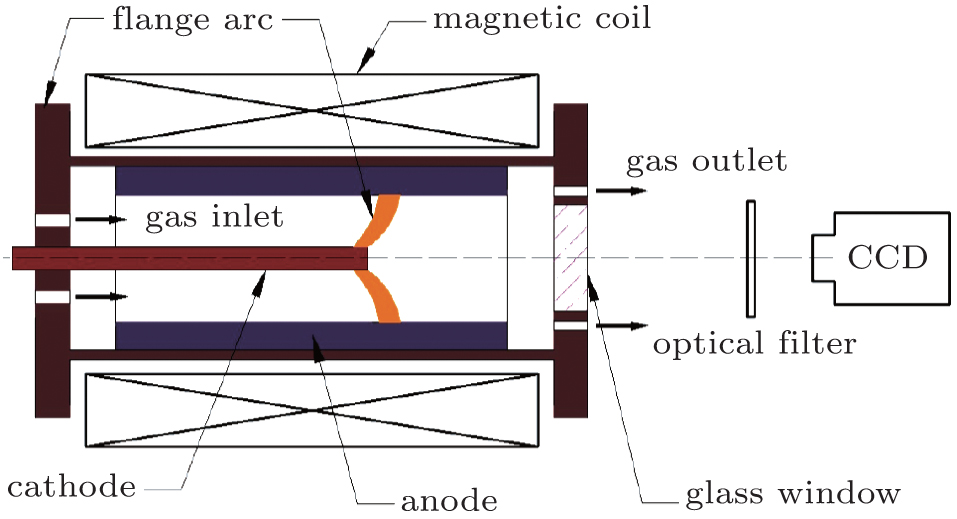 | Fig. 1. Schematic diagram of the experimental equipment. |
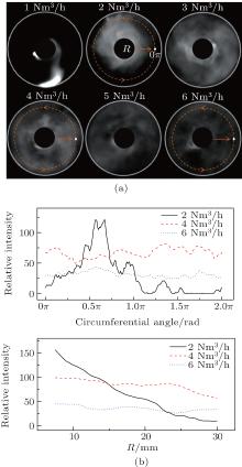
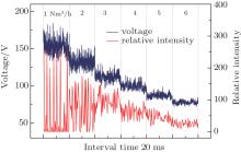
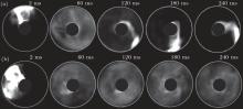
Figure 2 exhibits the images of arc plasmas at different inlet gas flows and corresponding radiation intensities along the circles and radial line. Time-resolved arc voltage waves and radiation intensities are shown in Fig. 3. The central black spots in images are shades of a mask, which is used to intercept the strong light emitted from the hot cathode in order to have a better observation of the arc configuration. Under 1-Nm3/h gas flow, a constricted arc column, which rotates anticlockwise at a speed of about 2000 rounds per second, is observed in the chamber, as shown in frame 1 in Fig. 2(a). The constricted arc column owns a distorted or helical structure. The average arc voltage reaches as high as 154 V. The arc voltage fluctuation (9 V standard deviation) is violent, due to the consecutive restrikes or reconnections of the current channel. Due to the presence of dark zones (cold gas areas), the time-resolved radiation intensity value varies from a minimum to 0 as exhibited in Fig. 3. With the increase of gas flow, the arc column expands gradually. Frame 2 in Fig. 2(a) is a typical image of chamber cross section partially filled with arc plasma at a gas flow of 2 Nm3/h. Successive images in this experiment indicate that the arc rotating cycle is about 1 ms, which is much longer than the exposure time (1 μ s). Thus, the expansive arc does not feint due to the high-rotating arc. Figure 3 shows that the average arc voltage decreases to 132 V with lower fluctuation (7-V standard deviation). The maximal radiation intensity of arc plasma decreases from 250 (saturated value) to less than 200, which indicates that the expansive arc temperature decreases. Therefore, the reduction of arc voltage indicates that the expansive arc should have a much shorter conductive channel or/and a much larger conductive area than the constricted mode, since the plasma resistivity increases with the decrease of plasma temperature.
 | Fig. 2. Typical images (a), and radiation intensity distributions along the circles (ϕ 50 mm) and the radial line (b), of arc plasmas under different inlet gas flows, I = 350 A, B = 0.2 T, 1-μ s shutter, 5000 fps, the outer white line in panel (a) represents the plasma chamber. |
With the increase of gas flow up to 3 Nm3/h– 6 Nm3/h, the arc plasma shows further expansion, and almost fills the entire cross section of the chamber as shown in frames 3 to 6 in Fig. 2(a). It also exhibits the reductions of brightness (radiation intensity) and temperature of diffuse plasma, while the intensity of radiation, which exists around the circumference and in the radial direction, is more homogeneous as shown in Fig. 2(b). When the arc transforms from constricted mode to diffuse mode, both voltage and noise of the arc exhibit a sharply falling evolution, decreasing from 154 V and 9 V at a gas flow of 1 Nm3/h to 80 V and 2 V at 6 Nm3/h, respectively. The relatively uniform radiation intensity distribution, reduced arc voltage and its lower fluctuation indicate that the expansive arc plasma is more uniform and stable. The existing fluctuation of arc voltage may arise from the current channel disappearing and rebuilding progress.[9]
 | Fig. 3. Time-resolved arc voltage waves and radiation intensities at point for different inlet gas flows corresponding to Fig. 2. |
The diffuse plasma images exhibit that non-uniform plasma cloud and some dark zones are disorderly mixed together. The phenomenon indicates the expansive plasma may originate from the arc being blown away, rather than the arc plasma diffusing. The result that the arc plasma expands gradually with the increase of inlet gas flow also proves that the expansive arc is governed by the gas flow.
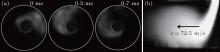
As shown in Fig. 4(a), when the magnetic field and arc currents are reduced to 0.04 T and 130 A, the arc plasma is dim, and covers only a small part of the chamber cross section. Under this condition, the arc plasma rotates at a speed of 600 rounds per second. The arc plasma fans out in the chamber, and its expansion is against the rotational direction. This phenomenon is similar to the torch plasma arc mode under a cross wind[19, 20] as shown in Fig. 4(b). Previous research reveals that there is a critical value of cross-wind velocity (∼ 10 m/s), at which the arc expands greatly to a large scale plasma.[19] The magnetic field drives the arc moving in the J × B direction. The moving velocity, which is on the order of ∼ 102 m/s, is probably higher than the critical cross-wind velocity. Hence, the arc expansion should result from the strong convection.
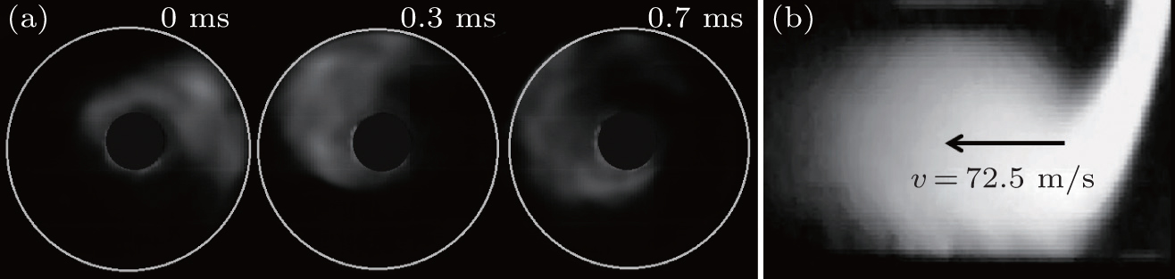 | Fig. 4. (a) Consecutive images of arc plasma with I = 130 A, B = 0.04 T, flow rate = 3 Nm3/h, 0.5-μ s shutter, 3000 fps, and (b) typical mode of torch plasma arc with lateral gas velocity (v).[19, 20] |
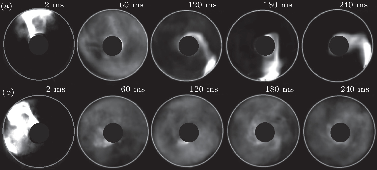 | Fig. 5. Evolution of arc plasma after ignition with I = 350 A, B = 0.2 T, 1-μ s shutter, 5000 fps, flow rates of (a) 0.5 Nm3/h, (b) 4 Nm3/h. |
Additionally, the convection effect on arc dispersion is proved after the arc has been ignited. Figure 5 shows the temporal dynamic evolutions of arc plasma under different gas flows. Under different inlet gas flows, the arc expands rapidly (frames at 2 ms in Figs. 5(a) and 5(b)), and fills the whole cross section of the chamber (frames at 60 ms in Figs. 5(a) and 5(b)). As time goes on, the expansive plasma gradually disappears and a luminous and constricted column appears (frame at 120 ms in Fig. 5(a)) under 0.5-Nm3/h gas flow. After 180 ms, the arc evolves into a constricted arc column (frames at 180 ms and 240 ms in Fig. 5(a)). In contrast, the DAP is maintained when the flow rate increases to 4 Nm3/h as shown in Fig. 5(b). It is inferred that the relative motion between the high-rotating arc and the relatively static ambient gas forms strong convection, which results in the formation of DAP within 60 ms. Then, the rotation arc drives the ambient gas moving in the J × B direction, so the convection is greatly weakened when little or no inlet gas flow is imposed. When enough flux is imposed, a considerable relative movement between the arc plasma and inlet gas flow could be maintained, thus, the DAP would be sustained in the chamber.
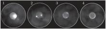
It was proposed that the uniformly distributed cathodic arc root governs the arc expansion.[6, 7, 18] As shown in Fig. 6, in order to investigate the effects of arc root behaviors on the expansive arc plasma, we modify the technology parameters to obtain various cathodic arc roots, including a single big root (frame 1), constricted multi-roots (frames 2 and 3), and a diffuse annular root (frame 4). The experiment shows that any arc roots could exist stably for a long period. It is also found out that the different arc roots could be converted to each other quickly. However, the DAP is consistent under various cathodic arc roots. Thus, the formation of DAP is independent of the cathodic arc root behaviors. However, the behaviors of cathodic arc roots have influences on the homogeneity and stability of DAP. Uniform diffuse cathodic root is helpful for implementing the homogenization and stabilization of DAP (frame 4 in Fig. 6).
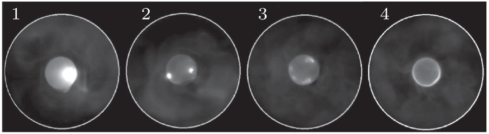 | Fig. 6. Images of DAP and corresponding cathodic arc roots with I = 250 A, B = 0.05 T, flow rate 4 Nm3/h, 0.5-μ s shutter, and 5000 fps. |
The evolution of magnetically rotating arc plasma into a large area plasma is investigated in this study. As the inlet gas flow increases, the constricted arc expands gradually; it could even fill the entire cross section of the generator chamber under enough inlet gas flow. With a small inlet gas flow, the arc expands during the period after the arc has been ignited, then it constricts gradually over time. Experimental results prove that the large area arc plasma derives from the fact that the arc column is dispersed by the convection which exists between the rotation arc and the ambient cold gas, thus this expansive arc plasma is called dispersed arc plasma (DAP). The relatively uniform radiation intensity distribution of arc plasma, reduced arc voltage, and its lower noise indicate that the DAP owns better homogeneity and stability. Furthermore, the DAP is independent of the behaviors of cathodic arc roots, but its homogeneity is affected by the non-uniform cathodic root to some extent.
The authors would like to thank Dr. Ding Wei-Xing for his useful discussion.
| 1 |
|
| 2 |
|
| 3 |
|
| 4 |
|
| 5 |
|
| 6 |
|
| 7 |
|
| 8 |
|
| 9 |
|
| 10 |
|
| 11 |
|
| 12 |
|
| 13 |
|
| 14 |
|
| 15 |
|
| 16 |
|
| 17 |
|
| 18 |
|
| 19 |
|
| 20 |
|