


Current–voltage characteristics of hydrogen DC plasma torches with different sizes in an external axial magnetic field*
[Ma Jie, Wen Guang-Dong, Su Bao-Gen† , Yang Yi-Wen, Ren Qi-Long]
, Yang Yi-Wen, Ren Qi-Long]
|
|


†Corresponding author. E-mail: subg@zju.edu.cn
*Project supported by the Special Fund for Basic Scientific Research of Central Colleges, China (Grant No. 2012FZA4023).
Current–voltage ( I– V) characteristics of hydrogen DC plasma torches with different sizes in an external axial magnetic field under atmospheric pressure are reported. Three anodes with different diameters are adopted in a 50-kW torch: 25 mm, 30 mm, and 35 mm, respectively. Two different diameters of anodes, that is, 100 mm and 130 mm, are adopted in a 1-MW plasma torch. The arc voltage shows a negative trend with the increase of arc current under the operating regimes. On the contrary, arc voltage shows a positive trend as the flow rate of carrier gas increases, and a similar trend is found with increasing the external magnetic flux density. A similarity formula is constructed to correlate the experimental data of the torches mentioned above. Linear fitting shows that the Pearson correlation coefficient is 0.9958.
Thermal plasmas have a great variety of applications in many industries, including arc welding, surface treating, ultrafine particle synthesis, carbon nanotubes production, etc.[1– 5] Owing to the advantages in high concentrated energy flux, high chemical reactivity, and high temperature, more and more attention has been paid to the plasma conversion of fossil resources and biomass to produce syngas or acetylene.[6, 7]
Due to the steep temperature gradient and non-uniformity inside the plasma jet, it is difficult to achieve good mixing between processing materials and the plasma jet.[1] A larger volume of homogeneous plasma could be obtained when an external magnetic field is applied.[8] Also the magnetically driving plasma arc will spread the heat load on the anode surface, reduce erosion of the electrode and increase the mixing efficiency, which has been used in the 1-MW plasma torch of AVCO[9] and the 9-MW plasma torch of DuPont.[10]
The current– voltage (I– V) characteristic is one of the major characteristics of the plasma torch.[11] This characteristic depends on both the geometry of the torch and operating parameters such as anode size, gas flow rate, working gas, etc. Shashkov and Yas’ Ko[12] introduced similarity theory to characterize the DC plasma around the 1970s, and many relevant dimensionless numbers were established. Similarity theory[12, 13] has been successfully used to study plasma characteristics. It provides a reasonable way to construct the relationship between experimental data and mathematical formula. Then the experimental workload could be reduced, and the corresponding plasma characteristics can be predicted. The similarity theory was used in DC vortex plasma torches, which included the button and well-type cathode by Brilhac et al.[14, 15] and Zhang et al.[16] reported the characteristics of a DC dual-jet plasma generator. Paingankar et al.[17] used the dynamic similarity to characterize a non-transferred plasma spray torch.
Therefore, it is of theoretical and practical significance to study the current– voltage (I– V) characteristic of the plasma torch for designing and operating the torch.
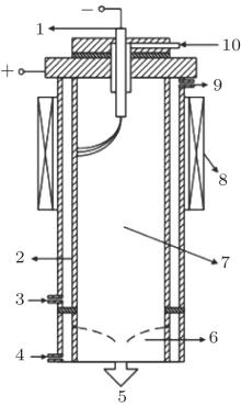
In the present work, two sets of plasma torches are designed and built. The corresponding powers are 50 kW (smaller one) and 1 MW (larger one), respectively; they are designed similarly in geometry as shown in Fig. 1. Both the plasma torches are conducted under a constant current power supply. The circuit voltages for the 50-kW torch and the 1-MW torch are 500 V and 2000 V, respectively. Atmospheric hydrogen plasmas are produced at different anode sizes, gas flow rates, and magnetic flux density (Table 1).
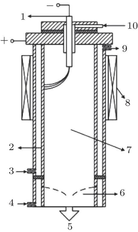 | Fig. 1. Schematic diagram of the experimental set-up. 1: cathode; 2: anode; 3: cooling water inlet; 4: quenching water inlet; 5: gas outlet; 6: quenching chamber; 7: anode chamber; 8: magnetic coil; 9: cooling water outlet; 10: gas entrance. |
| Table 1. Experimental conditions. |
The anode chamber can be reassembled with anodes of different sizes. Three anodes with different inner diameters are adopted in the 50-kW torch: 25 mm, 30 mm, and 35 mm, respectively. The corresponding diameters of the cathodes are 6 mm (50 kW) and 20 mm (1 MW), respectively.
For the 1-MW plasma torch, anodes with 100 mm and 130 mm are used. Cooling water continuously flows to the anode and the cathode to ensure the temperature of the plasma torch is kept at a reasonable limit level. All the experimental data are collected by a computer system.
The similarity theory provides a feasible way to generate a relationship between experimental data and mathematical formula, and then the corresponding plasma characteristics can be predicted.
According to Shashkov’ s theory, [12] considering thermal conductivity, electric field, and enthalpy as the major physical parameters, the relevant dimensionless numbers can be derived as follows:


Here, variables with subscript “ 0” refer to the reference values, G is the gas flow rate, μ the viscosity, L the difference in radius between anode and cathode, σ the electrical conductivity, h the specific enthalpy, λ the thermal conductivity, T the temperature, I the arc current, and U the arc voltage.
In this case, an additional external magnetic field is used in the plasma torch, so it should be taken into consideration. The dimensionless quantity about magnetic pressure is

Here, v0 is the initial gas inlet velocity, and B is the magnetic flux density. The Reynolds number associated with the magnetic field strength could be changed into

Then, the five dimensionless quantities involved can be obtained as


According to the five dimensionless quantities, the similarity formula can be written as

According to the power law approximation, [17] equation (12) could be expressed as

Physical properties of hydrogen under a certain reference temperature[13] are chosen as the reference values (Table 2) used in the formula above.
| Table 2. Reference values of H2 plasma.[13] |
The measured voltages of the lab-scale torch (anode diameter, D = 25 mm) at a constant arc current (I = 80 A) and external magnetic flux density (B = 0.094 T) are shown in Fig. 2. Results show that the arc voltage increases quickly as the gas flow rate increases at the beginning, and the curve flattens out gradually after a steep increase. This trend can be explained by the cooling wall effect. The cold gas will compress and stretch the arc column, thus leading to the rise of the arc voltage.[18] However, with the increase of gas flow rate (> 10 Nm3/h) in the turbulent regime, the arc voltage fluctuates little with the changes of gas flow rate and arc current.[18] Bora et al.[19] also showed a similar trend demonstrating the same effect of the gas flow rate.
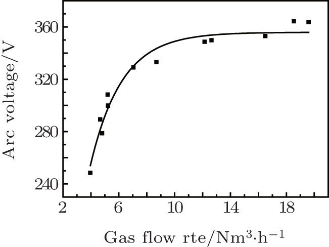 | Fig. 2. Effect of gas flow rates on the arc voltage (I = 80 A, B = 0.094 T, D = 25 mm). |
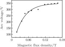
The influence of magnetic flux density on the current– voltage characteristic of the plasma torch (anode, D = 25 mm) is investigated under a constant current I of 80 A at a gas flow rate G of 5.6 Nm3/h. Figure 3 shows that the voltage increases with the increase of external magnetic flux density. With increasing the magnetic flux density, the arc column is stretched by an enhanced Lorentz force and becomes longer and the arc voltage increases. Also when the magnetic flux density B is more than 0.012 T, the increase of arc voltage becomes slower. Like the result of Barreto et al., [20] the increase in voltage at a higher rotation velocity is small. The reason is that when the arc column is stretched to a certain degree, dispersed plasma reaches a relatively steady state and the voltage will no longer strongly fluctuate.
 | Fig. 3. Effect of magnetic flux density on arc voltage (G = 5.6 Nm3/h, D = 25 mm, I = 80 A). |
Figure 4 shows the current– voltage characteristics of the plasma torch (anode, D = 25 mm, G = 7.5 Nm3/h) under different magnetic flux densities, where the arc voltage decreases with the increase of arc current. This negative trend is qualitatively consistent with previous results. The negative characteristic is due to the fact that the arc electric conductance increases with the increase of current intensity as a result of a decrease in electrical resistance.[21]
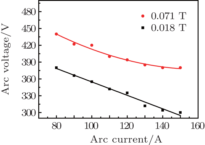 | Fig. 4. Current– voltage characteristics under different magnetic flux densities (G = 7.5 Nm3/h, D = 30 mm). |
Effect of anode sizes on the current– voltage characteristic in the 50-kW plasma torch (B = 0.094 T, G = 7.5 Nm3/h) is shown in Fig. 5. When anode length is fixed, anode size plays a major role in the current– voltage characteristic of a plasma torch. As illustrated, negative current– voltage characteristics can be found in each anode size, similar to that described in Subsections 4.1.1 and 4.1.2. Under otherwise identical operating conditions, arc voltage will increase with the increase of anode diameter. This could be explained for the spatially increasing of the arc column length.
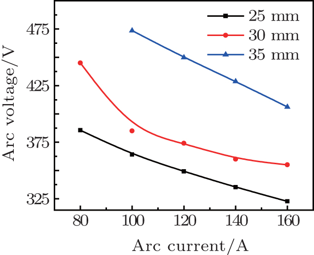 | Fig. 5. Effect of anode sizes on current– voltage characteristics (B = 0.094 T, G = 7.5 Nm3/h). |
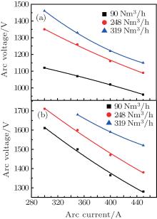
Figure 6 shows the I– V characteristics at different gas flow rates by using the 1-MW plasma torch with two different anodes (D = 100 mm and D = 130 mm) at a constant external magnetic flux density B of 0.11 T. In this figure, the arc voltage decreases with the increase of arc current just like the trend mentioned in Subsections 4.1.1– 4.1.3. Comparing Fig. 6(a) with Fig. 6(b), it can be concluded that no matter what the gas flow rate is, negative voltage characteristics can be expected to appear in the range of operating regimes. As the anode diameter increases, the voltage of the 130-mm torch becomes higher than that of the 100-mm torch, which is consistent with the trend discussed in Subsection 4.1.3.
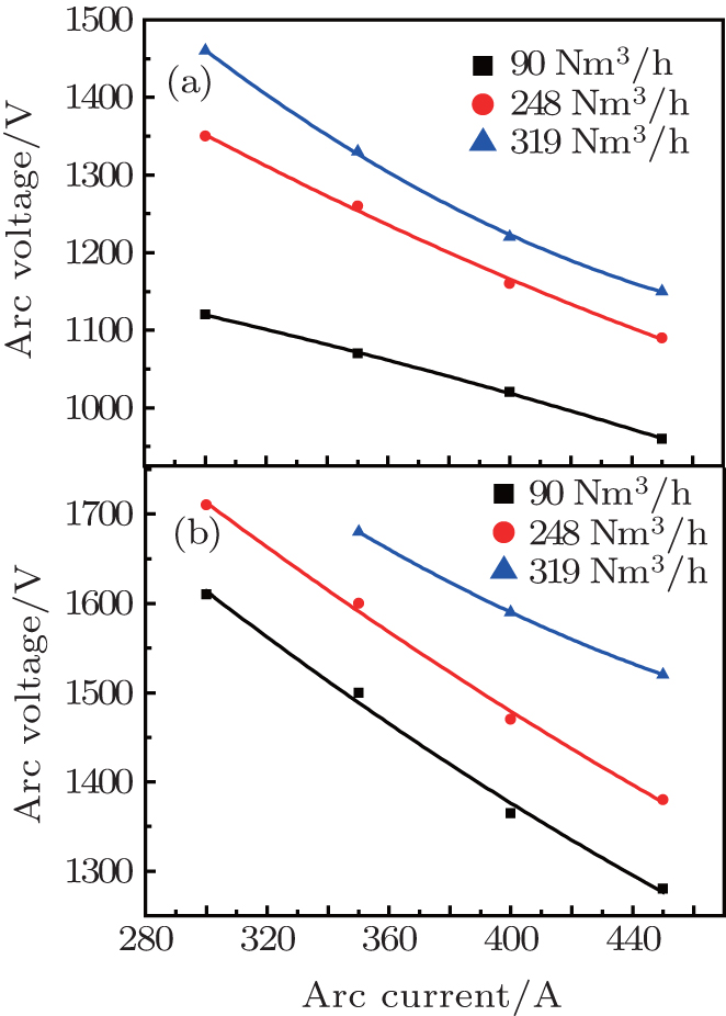 | Fig. 6. Experimental current– voltage characteristics under different gas flow rates (a): D = 100 mm, B = 0.11 T; (b): D = 130 mm, B = 0.11 T. |
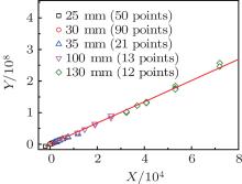
Dimensionless equations describing the physical phenomena in the plasma arc could be used to extrapolate the characteristics of one similar plasma generator.[14, 22] A generalized formula of I– V characteristics (Eq. (14)) is derived by the regression of experimental data under various operating conditions. Making the similarity formula fit by the experimental data, which is obtained from both the 50-kW and 1-MW plasma torches, coefficients of the similarity formula can be obtained as follows: C = 3207.67, a1 = − 0.53, a2 = − 0.37, a3 = 0.63, a4 = 1.30. Then the formula becomes
According to the formula, if we make

then we will have

Figure 7 shows the linear fittings of experimental data of both the 50 kW and 1 MW plasma torches given that Pearson’ s correlation coefficient r is 0.9958, which indicates the degree of linearity.
 | Fig. 7. Experimental data’ s linear fitting the similarity formula. |
In Table 1, it can be found that the experiments are carried out under relatively wide operating regimes. So the similarity formula obtained can be adapted to plasma torches with different sizes and be valuable for designing larger plasma torches.
Three anodes with different inner diameters for the 50-kW plasma torch are used: 25 mm, 30 mm, and 35 mm. For the arc current in a range between 80 A and 200 A, the arc voltage decreases with the increase of arc current. When the gas flow rate increases, the arc voltage increases. The same positive trend can be found when the magnetic flux density changes.
The negative current– voltage characteristics are found to be the same in the case of the 1-MW plasma torch with two anodes (inner diameters are 100 mm and 130 mm). The similarity theory is applicable to the characterization of the magnetically rotating DC plasma, and the formula which is satisfied by the experimental data of different torches is found to be reasonably appropriate. The linear fitting result shows that the Pearson correlation coefficient is 0.9958.
| 1 |
|
| 2 |
|
| 3 |
|
| 4 |
|
| 5 |
|
| 6 |
|
| 7 |
|
| 8 |
|
| 9 |
|
| 10 |
|
| 11 |
|
| 12 |
|
| 13 |
|
| 14 |
|
| 15 |
|
| 16 |
|
| 17 |
|
| 18 |
|
| 19 |
|
| 20 |
|
| 21 |
|
| 22 |
|