Zhang Yan-Yan, Yan Lu-Lu, Zhao Wen-Yu, Meng Sen, Fan Song-Tao, Zhang Long, Guo Wen-Ge, Zhang Shou-Gang, Jiang Hai-Feng. A long-term frequency-stabilized erbium-fiber-laser-based optical frequency comb with an intra-cavity electro-optic modulator* . Chinese Physics B, 2015, 24(6): 064209
Permissions
A long-term frequency-stabilized erbium-fiber-laser-based optical frequency comb with an intra-cavity electro-optic modulator*
Zhang Yan-Yana), Yan Lu-Lua), Zhao Wen-Yua),b), Meng Sena),c), Fan Song-Taoa),b), Zhang Longa), Guo Wen-Gec), Zhang Shou-Ganga), Jiang Hai-Fenga)†
Key Laboratory of Time and Frequency Standards, National Time Service Center, Xi’an 710600, China
University of the Chinese Academy of Sciences, Beijing 100049, China
School of Science, Xi’an Shiyou University, Xi’an 710065, China
*Project supported by the National Natural Science Foundation of China (Grant Nos. 91336101 and 61127901) and West Light Foundation of the Chinese Academy of Sciences (Grant No. 2013ZD02).
Abstract
We demonstrate an optical frequency comb based on an erbium-doped-fiber femtosecond laser with the nonlinear polarization evolution scheme. The repetition rate of the laser is about 209 MHz. By controlling an intra-cavity electro-optic modulator and a piezo-transducer, the repetition rate can be stabilized with a high-bandwidth servo in a frequency range of 3 kHz, enabling long-term repetition rate phase-locking. The in-loop frequency stability of repetition rate is about 1.6×10⁻¹³ in an integration time of 1 s, limited by the measurement system; and it is inversely proportional to integration time in the short term. Furthermore, using a common path f– 2 f interferometer, the carrier envelope offset frequency of the comb is obtained with a signal-to-noise ratio of 40 dB in a 3-MHz resolution bandwidth. Stabilized carrier envelope offset frequency exhibits a deviation of 0.6 mHz in an integration time of 1 s.
Keyword:
42.55.Wd; 42.62.Eh; 42.65.Re; optical frequency comb; fiber laser; frequency stabilization; frequency instability
Optical frequency combs, based on Ti:sapphire femtosecond laser, were invented at the end of 1990s.[1, 2] Two scientists from Germany and USA won the Nobel Prize for physics in 2005 due to this invention. Nowadays, optical frequency combs are widely used in many areas, including attosecond science, [3] spectroscopy, [4] astronomical spectrograph, [5] low-noise microwave generation, [6] distance measurement, [7] time and frequency transfer, [8] optical clock development and application, [9] etc. Requirements of various applications have motivated scientists and engineers to develop new optical combs based on different laser sources, such as Cr:LiSAF, [10] Er:fiber, [11] Cr:forsterite, [12] Er:Yb:glass, [13] Yb:fiber.[14] Especially, erbium-doped fiber frequency comb attracts much attention because of its compactness, reliability, low power consumption, and directly covering telecommunication wavelength. As a result, Er:fiber frequency comb rapidly evolves, and its performance is as good as that of the best comb; the frequency stability of optical spectrum transfer can reach ∼ 1× 10− 17 in an averaging time of 1 s.[15]
Since the optical frequency comb was invented, ultra-high-resolution optical frequency measurement has become one of the most important applications. In order to meet the need of this application, some critical techniques were proposed to improve the frequency stability of the comb.[16– 19] Optical frequency of a comb can be expressed as ν n = fceo + nfr, [20] where fceo is the carrier envelope offset frequency, fr is the repetition rate, n is an integer of 105∼ 106. A small frequency fluctuation of fr can lead to a significant frequency variation of ν n. Consequently, fr definitely needs controlling in a high bandwidth to overcome the unexpected changes introduced by environmental noises or others. Traditionally, fr is controlled only with a piezo-transducer (PZT), whose response bandwidth is usually well below 10 kHz. To improve the control bandwidth of fr, scientists in JILA (USA) first realized fast servo of the repetition rate (∼ 230 kHz) by using an intra-cavity electro-optic modulator (EOM).[16] In China, a few research groups are developing a fiber-based comb system with an intra-cavity EOM.[21– 23]
In this paper, we present the progress of an erbium-fiber-laser-based optical frequency comb used for strontium optical clock frequency measurement. Its repetition rate (fr) is about 209 MHz. In order to control fr, an intra-cavity EOM and a long-range PZT are used as the feedback terminals simultaneously. Based on this configuration, fr can be stabilized continuously for more than one week. The response bandwidth of fr control is improved to megahertz, and the tunable range is 3 kHz. Moreover, the carrier envelope offset frequency (fceo) of the Er:fiber frequency comb, with a signal-to-noise ratio (SNR) of 40 dB in 3-MHz resolution bandwidth (RBW), is detected by a common path f– 2f interferometer. After stabilization, fceo exhibits a deviation of 0.6 mHz in an integration time of 1 s.
2. Experimental setup
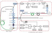
Figure 1 shows the setup of the optical frequency comb, which is based on an Er:fiber femtosecond laser. The laser output is divided into three parts. One part is the optical frequency comb output for the subsequent applications; the other two are used for detecting and stabilizing of fceo and fr respectively.
Fig. 1. Schematic diagram of the Er:fiber femtosecond laser frequency comb. The thick solid lines represent free-space paths, the thin solid lines represent fiber paths, and the dotted lines represent electrical paths. λ /2: half-wave plate; λ /4: quarter-wave plate; WDM: wavelength division multiplexer; ISO: isolator; PBS: polarization beam splitter; CO: collimator; PD: photodetector; BPF: bandpass filter; PPLN: periodically poled lithium niobate; HNLF: highly nonlinear fiber; LF: loop filter; HVA: high voltage amplifier; SYN: synthesizer.
2.1. Er:fiber-based mode-locked laser
As shown in Fig. 1, the Er:fiber femtosecond laser source has a ring cavity including four wave plates, a polarization beam splitter (PBS), two collimators, a WDM with isolator, an EOM, and fibers. A 2-cm PZT mounted on a stage is employed to control the cavity length. The cavity contains 39-cm SMF-28 fiber, 8-cm HI-1060 fiber, and 39-cm highly erbium-doped fiber (Liekki ER110-4/125). The net dispersion of the cavity is assumed to be slightly negative, considering all components and fibers in the cavity. The laser is pumped with two single-mode 980-nm pigtailed diode lasers, whose powers are both up to 0.6 W. By setting wave plates at proper angles, the laser can start mode-locking automatically while the pumping power is 1 W. Unfortunately, the mode-locked laser works in a multi-pulse state in this condition. In order to avoid this situation, we reduce the pump power to around 350 mW. The output power is ∼ 50 mW, and the duration of the pulse emitted from PBS is ∼ 83 fs with a 3-dB optical spectrum width of ∼ 50 nm.
Two feedback terminals, an EOM and a PZT, are employed to control fr. The EOM is an 8-mm long lithium niobate crystal with ∼ 800 fs2 dispersion at a wavelength of 1550 nm. To measure the response bandwidth of the EOM, we set up a Mach– Zehnder interferometer which contains the EOM in one arm. Then, we drive the EOM with an external radio-frequency (RF) source and monitor the phase response of the EOM at the output of the interferometer using a 2-GHz bandwidth photodetector (PD). The 3-dB bandwidth in magnitude is about 10 MHz, while the phase delay is close to π /2. The monotonic change of fr caused by EOM is about 60 Hz while tuning the offset voltage of EOM from − 200 V to 200 V. The tuning range of the PZT (from 0 V to 200 V) is measured to be around 3 kHz with a response bandwidth of hundreds of Hertz.
2.2. The fr detection and stabilization
To detect the repetition rate, we send a fraction of the output from the mode-locked laser into an InGaAs PD (EOT-3000A) with a bandwidth of 2 GHz. At the output of the PD, we obtain a current pulse train exhibiting m × fr in frequency domain, where m is an integer. Usually, we do not stabilize fr directly, but stabilize its high order harmonics, so as to reduce technical noise induced by the phase-locking process. However, no high frequency microwave synthesizer is available for the moment in our laboratory. Eventually, we lock the phase of the fourth harmonics of the repetition rate (838 MHz) to a reference signal.
The repetition rate is stabilized with a standard phase-locked loop technique. The phase detector is an RF mixer which produces an error signal indicating phase difference between 4fr signal and the reference signal. Following the mixer, a home-made loop filter converts the error signal into a negative feedback signal for driving EOM with high bandwidth and PZT with long range. Although the EOM has a response bandwidth of about 10 MHz, the control bandwidth of EOM servo-loop is estimated to be 100 kHz– 200 kHz according to the response measurement results of the home-made loop-filter and high voltage amplifier. The PZT control-loop has a bandwidth lower than 100 Hz for compensating only the temperature drift effect.
In addition, fr keeps being phase-locked while the box of the laser is hit, because EOM control-loop cancels the vibration influence efficiently. The peak-to-peak temperature fluctuation is about 1 ° C in the laboratory, and well below 1 ° C in the laser box, so that PZT control-loop can eliminate the thermal drift effect independently. Extra thermal control is not required. As a result, fr of the laser can be continuously phase-locked onto the reference signal over a week.
2.3. The fceo detection and stabilization
We use f– 2f interference method to produce fceo signal; and lock fceo to an extra-reference (radio-frequency RF) signal in phase by controlling the ring laser’ s pump power.
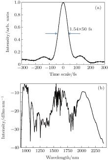
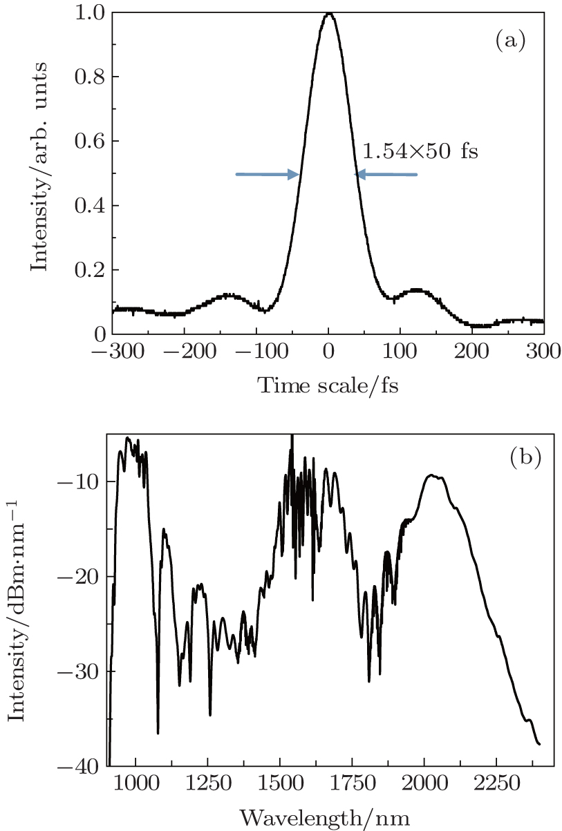
In order to perform f– 2f interference, we first prechirp the seed pulses for reducing the pulse peak’ s power, aiming to reduce the nonlinear effect in amplification stage. Secondly, the prechirped pulses are delivered into an erbium-doped fiber amplifier with a selective optimum gain of ∼ 14 dB. Thirdly, laser pulse width is compressed by dechirping the amplified pulses with an SMF-28 fiber, thereby yielding ∼ 50-fs pulses as shown in Fig. 2(a). Fourthly, these narrow pulses are fed into a short highly nonlinear fiber (HNLF), resulting in an octave-spanning supercontinuum (SC) as shown in Fig. 2(b). This figure gives the optical spectrum of the SC spanning from 950 nm to 2250 nm for 25-dB bandwidth. Most of the energy shifts into two solitons with 1-μ m and 2-μ m wavelengths respectively. It is worth noting that these two solitons have exactly the right wavelength for f– 2f interference. After that, all optical powers go through a 1-mm thick PPLN crystal for frequency-doubling. Finally, we pick-up 1-μ m-wavelength light with a 10-nm-wavelength bandpass filter and obtain a beatnote signal of f– 2f interference with an InGaAs PD.
Fig. 2. (a) Measured intensity autocorrelation of the compressed pulse; (b) octave-spanning supercontinuum produced with HNLF.
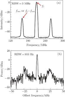
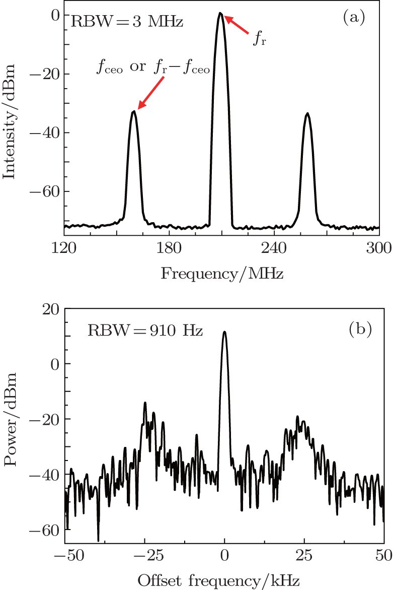
Figure 3(a) shows the spectrum of the f– 2f interference with 3-MHz RBW, showing an SNR of fceo to be 40 dB. The linewidth of the free-running fceo beat is about 500 kHz observed in fine RBW. The SNR is about 20-dB higher than that of the previously reported Er:fiber domestic system.[22] High SNR enables the system to generate a clean feedback signal for controlling the pump power and stabilizing fceo on a reference frequency provided with a synthesizer. A 20× frequency divider is used to improve the phase locking tolerance, making the phase-locked loop more robust. The control bandwidth of the loop is about 25 kHz indicated by the gain-bump as shown in Fig. 3(b). The accumulated noise power in a frequency range of 50 kHz– 10 Hz from the carrier is about 1%, indicating that the linewidth of frequency-divided fceo should be well below 1 Hz. More accurate evaluation will be shown later with frequency stability.
Fig. 3. (a) Spectrum of the f– 2f interference in 3-MHz RBW; (b) spectrum of the frequency-divided fceo signal in 910-Hz RBW.
The longest continuous phase-locking time of fceo is more than one day. However, some unknown noises coupled from electric ground (introduced by other events) disturb the phase-locked loop from time to time. We suppose that fceo can be stabilized much longer if the electric ground turns clean.
3. Results and discussion
Frequency stability of the optical frequency comb is one of the most important parameters. Measurement of the comb’ s absolute (out-of-loop) frequency instability requires two independent systems which are unavailable now. Here, we measure only in-loop frequency instability which does not include part of the fiber noise in comparison with the out-of-loop one.
3.1. In-loop frequency stability of fr
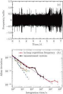
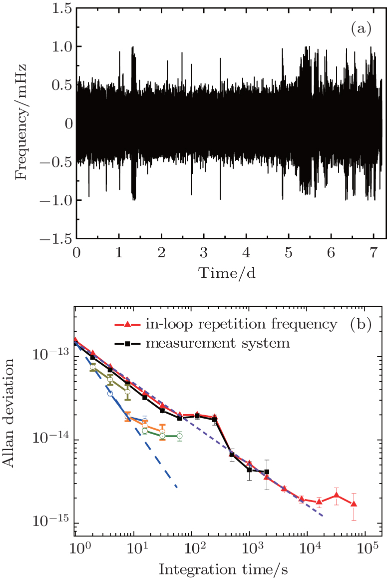
As shown in Fig. 1, down-converted frequency of 4fr at 1 MHz is recorded with a frequency counter (Agilent 53230A). Figure 4(a) shows the frequency fluctuation of 4fr, measured over a week. The result exhibits a root-mean-square (RMS) value of about 0.1 mHz. The frequency stability (Δ fr/fr) shown in Fig. 4(b) is about 1.6× 10− 13 in an integration time of 1 s. However, this result is limited by the noise floor as shown with solid squares, which is measured by using the same counter recording a 1-MHz reference signal. On the other hand, the frequency stability is inversely proportional to τ 1/2, where τ is the integration time, because the dead-time decouples the data relationship in measurement system and converts the white phase noise into a white frequency noise.[24] For a phase-locked loop, the stabilized signal should exhibit the white phase noise, and its frequency stability should be inversely proportional to τ . This is verified by eliminating dead-time effect with different gate times as shown with a dashed line in Fig. 4(b). Note that the first point of calculated Allan deviations has no dead-time effect. Therefore, the frequency stability of fr is about 1.6× 10− 13 in an integration time of 1 s and rolls down with a slope of 1/τ for short-term stability.
Fig. 4. (a) Residual fluctuations of the 4th harmonic of the repetition rate. The gate time is 1 s and the dead-time between samplings is about 0.2 s; (b) in-loop frequency stability of 4fr, measured with different gate (solid red triangle for 1 s, empty round for 2 s, 4 s, 8 s, and 16 s) times and measurement noise floor (solid black square).
3.2. In-loop frequency stability of fceo
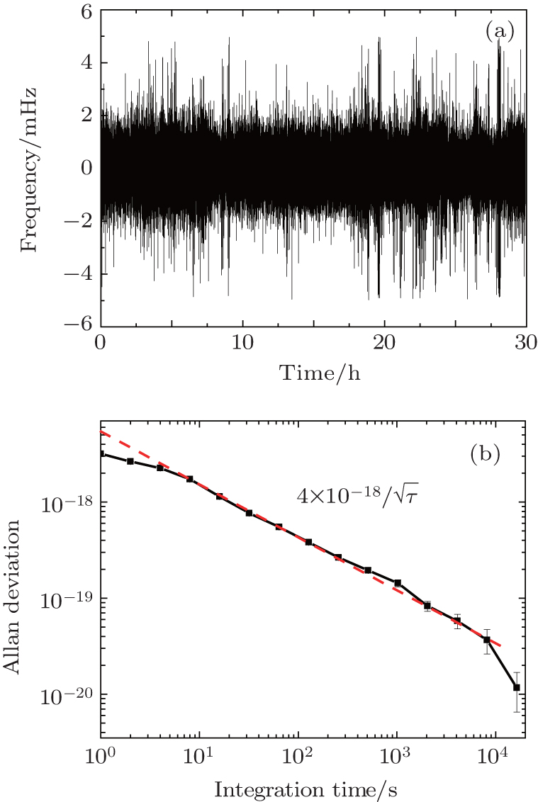
The RMS of fceo fluctuation is about 0.6 mHz in an integration time of 1 s, and the peak-to-peak fluctuation is about 10 mHz as shown in Fig. 5(a). Considering the fact that the optical frequency is about 200 THz, the corresponding optical comb frequency stability induced by in-loop fceo fluctuation is about 4× 10− 18/τ 1/2 as shown in Fig. 5(b).
Fig. 5. (a) Residual fluctuation of the stabilized in-loop CEO frequency; (b) optical comb frequency instability induced by in-loop fceo fluctuation.
It is clear that the frequency stability induced by in-loop fceo fluctuation is negligible even compared with the highest stable atomic clock with a stability of 3.2 × 10− 16/τ 1/2.[25, 26]
4. Conclusion and prospect
In this work, we demonstrate a home-made Er:fiber-based optical frequency comb with an intra-cavity EOM. To the best of our knowledge, this optical frequency comb is the first domestically-made one with a fast fr controller in the laser cavity. Both fr and fceo of the comb can be stabilized continuously over a long time, owing to the high bandwidth frequency control and high SNR of frequency signals detection. The frequency instability of the system is well below 1.6× 10− 13 in 1 s and rolls down with a slope of 1/τ for a short term. In the future, we will continuously optimize the system, and extend its operation frequency to strontium clock transition (698 nm) for frequency measurement.
Rosenband T, HumeD B, SchmidtP O, ChouC W, BruschA, LoriniL, OskayW H, DrullingerR E, FortierT M, StalnakerJ E, DiddamsS A, SwannW C, NewburyN R, ItanoW M, Wineland D J and BergquistJ C2008Science3191808DOI:10.1126/science.1154622[Cited within:1]
10
HolzwarthR, ZimmermannM, UdemT, HänschT W, RussbüldtP, GäbelK, PopraweR, KnightJ C, WadsworthW J and RussellP S J2001Opt. Lett. 261376DOI:10.1364/OL.26.001376[Cited within:1][JCR: 3.385]
KimK, WashburnB R, WilpersG, OatesC W, HollbergL, NewburyN R, DiddamsS A, NicholsonJ W and YanM F2005Opt. Lett. 30932DOI:10.1364/OL.30.000932[Cited within:1][JCR: 3.385]
LudlowA D, HuangX, NotcuttM, Zanon-WilletteT, ForemanS M, BoydM M, BlattS and YeJ2007Opt. Lett. 32641DOI:10.1364/OL.32.000641[Cited within:1][JCR: 3.385]
MilloJ, BoudotR, LoursM, BourgeoisP Y, LuitenA N, Le CoqY, KersaléY and SantarelliG2009Opt. Lett. 343707DOI:10.1364/OL.34.003707[Cited within:1][JCR: 3.385]
20
YeJ and CundiffS T2005Femtosecond Optical Frequency Comb: Principle, Operation and ApplicationsBerlinSpringer16[Cited within:1]
BloomB J, NicholsonT L, WilliamsJ R, CampbellS L, BishofM, ZhangX, ZhangW, BromleyS L and YeJ2014Nature50671DOI:10.1038/nature12941[Cited within:1]
26
HinkleyN, ShermanJ A, PhillipsN B, SchioppoM, LemkeN D, BeloyK, PizzocaroM, OatesC W and LudlowA D2013Science3411215DOI:10.1126/science.1240420[Cited within:1]
1
2000
7.943
0.0
... [1,2] Two scientists from Germany and USA won the Nobel Prize for physics in 2005 due to this invention ...
1
2000
0.0
0.0
... [1,2] Two scientists from Germany and USA won the Nobel Prize for physics in 2005 due to this invention ...
1
2011
0.0
0.0
... Nowadays, optical frequency combs are widely used in many areas, including attosecond science,[3] spectroscopy,[4] astronomical spectrograph,[5] low-noise microwave generation,[6] distance measurement,[7] time and frequency transfer,[8] optical clock development and application,[9] etc ...
1
2007
38.597
0.0
... Nowadays, optical frequency combs are widely used in many areas, including attosecond science,[3] spectroscopy,[4] astronomical spectrograph,[5] low-noise microwave generation,[6] distance measurement,[7] time and frequency transfer,[8] optical clock development and application,[9] etc ...
1
2007
5.521
0.0
... Nowadays, optical frequency combs are widely used in many areas, including attosecond science,[3] spectroscopy,[4] astronomical spectrograph,[5] low-noise microwave generation,[6] distance measurement,[7] time and frequency transfer,[8] optical clock development and application,[9] etc ...
1
2011
27.254
0.0
... Nowadays, optical frequency combs are widely used in many areas, including attosecond science,[3] spectroscopy,[4] astronomical spectrograph,[5] low-noise microwave generation,[6] distance measurement,[7] time and frequency transfer,[8] optical clock development and application,[9] etc ...
1
2009
27.254
0.0
... Nowadays, optical frequency combs are widely used in many areas, including attosecond science,[3] spectroscopy,[4] astronomical spectrograph,[5] low-noise microwave generation,[6] distance measurement,[7] time and frequency transfer,[8] optical clock development and application,[9] etc ...
1
2013
27.254
0.0
... Nowadays, optical frequency combs are widely used in many areas, including attosecond science,[3] spectroscopy,[4] astronomical spectrograph,[5] low-noise microwave generation,[6] distance measurement,[7] time and frequency transfer,[8] optical clock development and application,[9] etc ...
1
2008
0.0
0.0
... Nowadays, optical frequency combs are widely used in many areas, including attosecond science,[3] spectroscopy,[4] astronomical spectrograph,[5] low-noise microwave generation,[6] distance measurement,[7] time and frequency transfer,[8] optical clock development and application,[9] etc ...
1
2001
3.385
0.0
... Requirements of various applications have motivated scientists and engineers to develop new optical combs based on different laser sources, such as Cr:LiSAF,[10] Er:fiber,[11] Cr:forsterite,[12] Er:Yb:glass,[13] Yb:fiber ...
1
2003
3.546
0.0
... Requirements of various applications have motivated scientists and engineers to develop new optical combs based on different laser sources, such as Cr:LiSAF,[10] Er:fiber,[11] Cr:forsterite,[12] Er:Yb:glass,[13] Yb:fiber ...
1
2005
3.385
0.0
... Requirements of various applications have motivated scientists and engineers to develop new optical combs based on different laser sources, such as Cr:LiSAF,[10] Er:fiber,[11] Cr:forsterite,[12] Er:Yb:glass,[13] Yb:fiber ...
1
2010
1.782
0.0
... Requirements of various applications have motivated scientists and engineers to develop new optical combs based on different laser sources, such as Cr:LiSAF,[10] Er:fiber,[11] Cr:forsterite,[12] Er:Yb:glass,[13] Yb:fiber ...
1
2008
27.254
0.0
... [14] Especially, erbium-doped fiber frequency comb attracts much attention because of its compactness, reliability, low power consumption, and directly covering telecommunication wavelength ...
1
2014
27.254
0.0
... [15] ...
2
2005
3.385
0.0
... [16#cod#x2013 ...
... [16] In China, a few research groups are developing a fiber-based comb system with an intra-cavity EOM ...
1
2007
3.385
0.0
1
2010
27.254
0.0
1
2009
3.385
0.0
... 19] Optical frequency of a comb can be expressed as #cod#x03BD ...
1
2005
0.0
0.0
... nfr,[20] where fceo is the carrier envelope offset frequency, fr is the repetition rate, n is an integer of 105#cod#x223C ...
1
2014
1.782
0.0
... [21#cod#x2013 ...
1
2012
1.016
1.691
... [22] High SNR enables the system to generate a clean feedback signal for controlling the pump power and stabilizing fceo on a reference frequency provided with a synthesizer ...
1
2014
3.385
0.0
... 23] ...
1
2002
0.0
0.0
... [24] For a phase-locked loop, the stabilized signal should exhibit the white phase noise, and its frequency stability should be inversely proportional to #cod#x03C4 ...
1
2014
0.0
0.0
... [25,26] ...
1
2013
0.0
0.0
... [25,26] ...
A long-term frequency-stabilized erbium-fiber-laser-based optical frequency comb with an intra-cavity electro-optic modulator*
[Zhang Yan-Yana), Yan Lu-Lua), Zhao Wen-Yua),b), Meng Sena),c), Fan Song-Taoa),b), Zhang Longa), Guo Wen-Gec), Zhang Shou-Ganga), Jiang Hai-Fenga)†]


 ]
]