


High coupling efficiency and low signal light loss (2 + 1) × 1 coupler*
[Chen Xiaoa) , Xiao Qi-Rongb) , Jin Guang-Yonga) , Yan Pingb) , Gong Ma-Lib)†  ]
]
]
|
|


†Corresponding author. E-mail: gongml@mail.tsinghua.edu.cn
*Project supported by the National Natural Science Foundation of China (Grant No. 61307057) and the Fund from the State Key Laboratory of Tribology, Tsinghua University (Grant No. SKLT12B08).
The coupling efficiency of the pump coupler determines the pump light injection capacity of a laser system. Experimental analysis of the influences of different factors on the pump coupling efficiency is in accordance with this conclusion. We use two Nufern fibers (400 μm/440 μm with NA = 0.22) as pump arm, one Nufern fiber (20 μm/400 μm with NA = 0.06/0.46) as a main fiber to make a side-pumping (2+1)× 1 coupler. The experimental result shows that the total output power of this (2+1)× 1 coupler is about 1160 W, corresponding to a coupling efficiency as high as 98.6%. The loss of signal light is less than 1%.
High power all-fiber lasers and amplifiers play an important role in industrial production, and will gradually replace the traditional mechanical equipment. In recent years, the taper fiber bundle (TFB) end pumping geometries[1] and the side pumping geometries have become two main pump configurations for fiber lasers and amplifiers.
For a TFB end pumping coupler, the individual fibers can be bundled together in a close-packed formation, heated to melting temperature, drawn into a taper and then fusion spliced to the cladding-pumped fiber. The TFB end pumping couplers can be divided into two classes of couplers, i.e., N × 1 coupler and (N + 1) × 1 coupler. For a TFB side pumping coupler, each pump fiber is heated to melting temperature, drawn into a taper and then fusion spliced to the side of the cladding-pumped fiber. The TFB side pumping couplers can be divided into (N + 1) × 1 couplers. With the side-pumping, not only longer fiber could be used to ensure relatively uniform distribution of upper-level inversion particles, but also the thermal problem could be better solved. A lot of side-pumping methods have been demonstrated: non-all-fibered side-coupling configurations include the prime-fiber coupler, [2] the V-groove side coupling technique, [3] the enhanced evanescent field coupling method, [4] and the embedded mirror method; [5] the monolithic all-fibered coupling systems include the angle polished side coupler, [6] the side grating coupler, [7] the etched silicon capillary side coupler, [8, 9] the GT-wave coupler, [10] and the direct fusion side coupler.[11– 16] The monolithic all-fibered systems are more stable and more efficient than non-all-fibered configurations.
Currently commercial pump couplers have achieved the coupling of pump power of more than 200 W by one pump arm. International fiber laser company IPG has realized a 10-kW class laser output in an all-fiber configuration. However, the manufacture technique of its pump couplers remains unknown to outsiders.[17] ITF Canadian, providing a lot of fiber-coupled devices for the upstream fiber laser companies, has achieved a total output power of 2.4 kW from a (6 + 1) × 1 pump coupler.[18] Andrea et al. have demonstrated a monolithic (fully fused) Yb-doped fiber laser with an output power of 1.2 kW and near-single-mode beam quality.[19] In this fiber laser, the pump power was combined using a 19 × 1 fused-fiber combiner with a measured loss of < 1% , providing a nominal pump power of 1.8 kW.[20]
In the present paper by using Beamprop software we design side-pumping (2 + 1) × 1 coupler model and analyze the influences of different factors on the pump coupling efficiency. By comparing the discretion of the coupling efficiency, it can be eventually clarified that the number of pump arms, tapered length, and input mode field play a key role in producing (2 + 1) × 1 coupler. In accordance with this conclusion we make side-pumping (2 + 1) × 1 coupler. The experimental results show that a total output power of this (2 + 1) × 1 coupler is about 1160 W, corresponding to a coupling efficiency as high as 98.6% , and the loss of signal light is less than 1% . Meanwhile, the (2 + 1) × 1 coupler with high coupling efficiency, high output power, and low signal light loss can be used in a high power fiber laser system.
One-armed coupling efficiency refers to the coupling efficiency of a single fiber coupler, which is the ratio of output power to input power. The one-armed coupling efficiency is one of the most important performance parameters of the coupler, directly reflects the coupler manufacture quality, and is mathematically expressed as

where Pout i is the pump output power by i-th pump fiber, Pin is the output power of the LD, the ability of tolerance power is greatly influenced by pump coupling efficiency. The lower the coupling efficiency, the harder the thermal management is and the lower pump power the pump coupler withstands.
The coupling efficiency is the mean of all the simultaneous input fiber injection pump light, and mathematically expressed as

The Pout for output power of all output fibers, and Pin is the total output power by seven LDs.
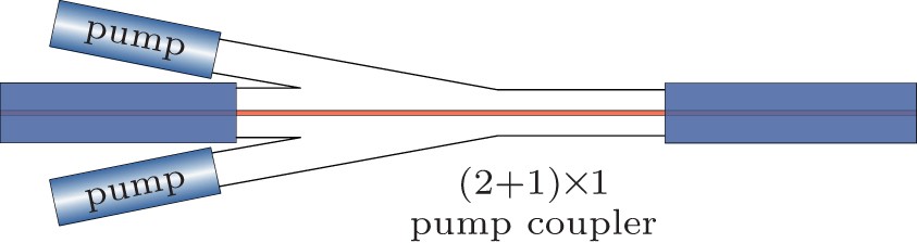
The schematic side view of a side-pumped coupler which consists of a DC fiber and an MM pump fiber with a silica-clad doped with fluorine and a tapered section is shown in Fig. 1. The silica-clad doped with fluorine (C region in Fig. 1) is between the core (B region in Fig. 1) of MM pump fiber and the inner-clad (A region in Fig. 1) of DC fiber. The indexes of A and B regions are both 1.448. The index of silica-clad doped with fluorine is slightly smaller than those of MM fiber core and DC fiber inner-clad, for example, the index of C region is 1.4402 when the MM pump fiber of 105 μ m/125 μ m (0.15) is used. The index difference between A(B) region and C region is 0.0078, so the cladding of MM pump fiber forms a refractive index valley (RIV) between the core of MM pump fiber and the inner-clad of DC fiber. The whole length of tapered MM pump fiber is converged with the inner-clad of DC fiber, forming the coupling region, and we assume that MM pump fiber fused to DC fiber perfectly. The efficiency of pump light transferring into the DC fiber is described by a pump coupling efficiency. A slight taper ratio leads to the coupling of the highest order modes of the MM pump fiber into the DC fiber. In addition, the transversal electromagnetic fields of the lower order modes expand more in the cladding of the MM pump fiber than the fields of the higher order modes, i.e., the lower order modes would prefer evanescent wave coupling.
 | Fig. 1. Schematic side view of a side-pumping system consisting of a DC fiber and an MM fiber with a silica-clad doped with fluorine. |
In Beamprop software we design a side-pumping (2 + 1) × 1 coupler model (pump arm: 220 μ m/242 μ m with NA = 0.22, and main fiber: 30 μ m/250 μ m with NA = 0.46), a side-pumping coupler is designed with a two-dimensional (2D) scalar model. In the side-pumping (N + 1) × 1 coupler, the pump arms were closely combined with the main fiber. One or more pump arms were symmetrically arranged around the main fiber. (i) The coupling efficiencies of (1 + 1) × 1 coupler and (2 + 1) × 1 coupler with the same tapered length and the same input mode field are studied and compared with each other. (ii) The coupling efficiencies of (2 + 1) × 1 couplers with the same input mode field and different tapered lengths are studied and compared with each other. (iii) The coupling efficiencies of (2 + 1) × 1 couplers with the same tapered length and the different input mode fields are studied and compared with each other. (iv) The coupling efficiencies of (2 + 1) × 1 couplers with the same input mode field and the different two pump tapered lengths inside each of (2 + 1) × 1 couplers are studied and compared with either.
The coupling efficiencies of (1 + 1) × 1 and (2 + 1) × 1 couplers with the same tapered length and the same input mode field are studied and compared with each other, and the results are shown in Fig. 2. The simulation model is developed under the condition of the same Gauss input mode field, a pump arm 220 μ m/242 μ m using the melt pulling taper coupling technology to make a tapered length of 8 cm, and two pump arms fitted on two sides of the main fiber 30 μ m/250 μ m. Figure 2(a) shows that the tapered length is 8 cm, the coupling efficiency of (1 + 1) × 1 coupler is 90.35% . In the figure the green line represents the optical power through one pump arm, the red line represents the optical power through the main fiber and the dark blue line represents the total pump coupler coupling efficiency. The white pattern of energy propagation indicates the saturation region. The rightmost scale 0.0– 1.0 represents the light intensity. Figure 2(b) shows that the tapered length is 8 cm and the coupling efficiency of (2 + 1) × 1 is 89.66% , the green line and red line represent the optical power through two pump arms. In the figure the light blue line represents the optical power through the main fiber and the dark blue line represents the total pump coupler coupling efficiency. The white pattern of energy propagation indicates the saturation region. The rightmost scale 0.0– 1.0 indicates the light intensity. By comparing the coupling efficiencies it can be eventually clarified that the coupling efficiency of (1 + 1) × 1 coupler is higher than that of (2 + 1) × 1 coupler under the same tapered length and the same input mode field. It implies that the coupling efficiency is determined mainly by the number of pump arms. It means that the (2 + 1) × 1 coupler is difficult to fabricate.
 | Fig. 2. Coupling efficiencies of (1 + 1) × 1 and (2 + 1) × 1 couplers with the same tapered length and the same input mode field. (a) Tapered length 8 cm, coupling efficiency 90.35% ; (b) tapered length 8 cm, coupling efficiency 89.66% . The arbitrary unit is abbreviated to a.u. in the figure. |
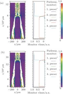
The coupling efficiencies of (2 + 1) × 1 couplers with the same input mode field and the different tapered lengths are studied and compared with each other, and the results are shown in Fig. 3. Simulation model is developed under the condition of the same Gauss input mode field, a pump arm 220 μ m/242 μ m using melt pulling taper coupling technology to make tapered lengths of 8 cm and 15 cm, and two pump arms fitted on two sides of the main fiber 30 μ m/250 μ m. Figure 3(a) shows that the tapered length is 8 cm, and the coupling efficiency is 89.66% , and figure 3(b) shows that the tapered length is 15 cm and coupling efficiency is 90.99% , In Fig. 3 the green line and the red line represent the optical powers through the two pump arms, the light blue line represents the optical power through the main fiber, and dark blue line represents the total pump coupler coupling efficiency. The white pattern of energy propagation indicates the saturation region. The rightmost scale 0.0– 1.0 represents the light intensity. By comparing the coupling efficiencies, it can be eventually clarified that the coupling efficiency of pump arm 15 cm is higher than that of pump arm 8 cm under the same input mode field. It implies that the coupling efficiency was determined mainly by the tapered length of the pump arm in the (2 + 1) × 1 coupler.
 | Fig. 3. Coupling efficiencies of (2 + 1) × 1 couplers with the same input mode field and the different tapered lengths. (a) Tapered length 8 cm, and coupling efficiency 89.66% ; (b) tapered length 15 cm, and coupling efficiency 90.99% . |
The coupling efficiencies of (2 + 1) × 1 couplers with the same tapered length and the different input mode fields are studied and compared with each other, and the results are shown in Fig. 4. A simulation model is developed under the condition of the same tapered length, different Gauss input mode fields of LP01 and LP33, and two pump arms fitted on two sides of the main fiber 30 μ m/250 μ m. Figure 4(a) shows LP01 mode and a coupling efficiency of 98.72% , and figure 4(b) shows LP33 mode and a coupling efficiency of 40.87% , In Fig. 4, the green line and red line represent the optical power through two pump arms, the light blue line represents the optical power through main fiber and the dark blue line represents the total pump coupler coupling efficiency. The white pattern of energy propagation indicates the saturation region. The rightmost scale 0.0– 1.0 represents the light intensity. By comparing the coupling efficiencies it can be eventually clarified that the coupling efficiency of LP01 mode is higher than that of LP33 mode under the same tapered length. It implies that the coupling efficiency is determined mainly by the Gauss input mode field in the (2 + 1) × 1 coupler. At the same time, when the input mode field is applied to the coupling place, the low-order mode is far more than the high-order mode.
 | Fig. 4. Coupling efficiencies of (2 + 1) × 1 couplers with the same tapered length and the different input mode fields. (a) LP01 mode, coupling efficiency 98.72% ; (b) LP33 mode, coupling efficiency 40.87% . |
The coupling efficiencies of (2 + 1) × 1 couplers with the same input mode field and the different two pump tapered lengths inside (2 + 1) × 1 coupler are studied and compared with each other, and the results are shown in Fig. 5. Simulation model is developed under the condition of the same Gauss input mode field, a pump arm 220 μ m/242 μ m using the melt pulling taper coupling technology to make tapered lengths of 5 cm, 8 cm, and 15 cm, and two pump arms fitted on two sides of the main fiber 30 μ m/250 μ m. Figure 5(a) shows tapered lengths of 8 cm and 5 cm, and a coupling efficiency of 88.23% , and figure 5(b) shows tapered lengths of 8 cm and 15 cm, and a coupling efficiency of 89.94% . In Fig. 5 the green line and the red line represent the optical power through two pump arms, the light blue line represents the optical power through the main fiber, the dark blue line represents the total pump coupler coupling efficiency, and the white pattern of energy propagation refers to the saturation region. The rightmost scale 0.0– 1.0 represents the light intensity. By comparing the coupling efficiencies it can be eventually clarified that the coupling efficiency of (2 + 1) × 1 coupler is determined mainly by the pump arm with longer tapered length.
 | Fig. 5. Coupling efficiencies of (2 + 1) × 1 couplers with the same input mode field and the different two pump tapered lengths inside (2 + 1) × 1 coupler. (a) Tapered length 8 cm and 5 cm, coupling efficiency 88.23% ; (b) tapered length 8 cm and 15 cm, coupling efficiency 89.94% . |
Through Beamprop software we design a side-pumping (2 + 1) × 1 coupler model (pump arm: 220 μ m/242 μ m with NA = 0.22, and main fiber: 30 μ m/250 μ m with NA = 0.46) and by comparing the coupling efficiencies it can be eventually clarified that number of pump arms, tapered length, and input mode field play a key role in producing a (2 + 1) × 1 coupler. In accordance with this conclusion we use two Nufern fibers (400 μ m/440 μ m with NA = 0.22) as pump arm, and one Nufern fiber (20 μ m/400 μ m with NA = 0.06/0.46) as a main fiber to make a (2 + 1) × 1 coupler as shown in Figs. 6 and 7.
 | Fig. 6. Schematic diagram of (2 + 1) × 1 coupler. |
 | Fig. 7. Photograph of a real (2 + 1) × 1 coupler. |
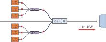
As shown in Fig. 8, we test the output pump power of the (2 + 1) × 1 coupler. Six LDs each with an output power of about 200 W are spliced with the six pumping arms of the new pump coupler, and the total output power of two 3× 1 couplers is about 1176 W. The corresponding spliced point loss is less than 1% . The end of output power is of a right-angle. A total output power of this (2 + 1) × 1 coupler is about 1160 W, and the corresponding coupling efficiency is as high as 98.6% . Comparing with the basic model by Beamprop software, we achieve a high coupling efficiency, which is due to the tapered length being longer. In experiment, we use longer tapered length to make the pump arm.
 | Fig. 8. The series connection pump coupler pump power test chart. |
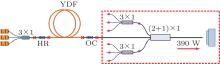
We set up a laser system to test series connection coupler signal light loss as shown in Fig. 9. In experiment, we use a pair of fiber Bragg gratings, gain fiber coupler, two transverse pump 3× 1 couplers. Through the pump end pump 3× 1 optical fiber coupler gaining, the shocks are formed by fiber grating laser output. The measured initial laser output power is about 395 W, and the shock system-light conversion efficiency is 65.8% . By fusion welding technology, the output end of the oscillator and the input end of the coupler' s main fiber were spliced together, realizing a laser output power of about 390 W. Behind the spliced point, the main fiber was truncated at a right angle, and the measured laser output power was about 391.5 W, corresponding to a melting point loss of 3.5 W and splicing loss of less than 0.89% . Through the analysis of composite system, the (2 + 1) × 1 coupler signal light loss is less than 1% .
 | Fig. 9. Diagram for testing signal loss of the series connection coupler. |
In this paper, by Beamprop software we design a side-pumping (2 + 1) × 1 coupler model (pump arm: 220 μ m/242 μ m with NA = 0.22, main fiber: 30 μ m/250 μ m with NA = 0.46) and analyze the influences of different factors on the pump coupling efficiency. By comparing the coupling efficiencies, it can be eventually clarified that number of pump arms, tapered length, and input mode field play a key role in producing a (2 + 1) × 1 coupler. In accordance with this conclusion we use two Nufern fibers (400 μ m/440 μ m with NA = 0.22) as a pump arm, one Nufern fiber (20 μ m/400 μ m with NA= 0.06/0.46) as a main fiber to make a side-pumping (2 + 1) × 1 coupler. The experimental result shows that a total output power of this (2 + 1) × 1 coupler is about 1160 W, corresponding to a coupling efficiency as high as 98.6% . The loss of signal light is less than 1% . Meanwhile, the (2 + 1) × 1 coupler with high coupling efficiency, high output power, and low signal light loss can be used in a high power fiber laser system.
| 1 |
|
| 2 |
|
| 3 |
|
| 4 |
|
| 5 |
|
| 6 |
|
| 7 |
|
| 8 |
|
| 9 |
|
| 10 |
|
| 11 |
|
| 12 |
|
| 13 |
|
| 14 |
|
| 15 |
|
| 16 |
|
| 17 |
|
| 18 |
|
| 19 |
|
| 20 |
|