


Dynamical characteristics of an HP memristor based on an equivalent circuit model in a chaotic oscillator*
[Yuan Fang, Wang Guang-Yi† , Wang Xiao-Yuan]
, Wang Xiao-Yuan]
|
|


†Corresponding author. E-mail: wanggyi@163.com
*Project supported by the National Natural Science Foundation of China (Grant Nos. 61271064 and 60971046), the Natural Science Foundation of Zhejiang Province, China (Grant No. LZ12F01001), and the Program for Zhejiang Leading Team of Science and Technology Innovation, China (Grant No. 2010R50010-07).
To develop real world memristor application circuits, an equivalent circuit model which imitates memductance (memory conductance) of the HP memristor is presented. The equivalent circuit can be used for breadboard experiments for various application circuit designs of memristor. Based on memductance of the realistic HP memristor and Chua’s circuit a new chaotic oscillator is designed. Some basic dynamical behaviors of the oscillator, including equilibrium set, Lyapunov exponent spectrum, and bifurcations with various circuit parameters are investigated theoretically and numerically. To confirm the correction of the proposed oscillator an analog circuit is designed using the proposed equivalent circuit model of an HP memristor, and the circuit simulations and the experimental results are given.
The memristor is known as the fourth basic circuit element, first postulated by Chua[1] in 1971. A memristor is a nonlinear resistor with memory. Unlike the resistor, whose relation between voltage and current is proportional and linear, the memristor’ s v– i characteristic is nonlinear. The first component with a memristor characteristic was built in the HP laboratory using nanotechnology.[2] Owing to the feature of being an intrinsically nonlinear element with memory, the memristor is considered to have started a new generation of computational circuits substituting for transistors and attracts much attention from researchers.
Since the first memristor was fabricated by HP, various application circuits based on the memristor have been widely studied, especially some chaotic circuits composed of Chua’ s circuits and a memristor. Active memristors with smooth piecewise-quadratic or cubic nonlinearity are employed to construct a series of memristor oscillation circuits in Refs. [3]– [6]. In Ref. [7], a memristor oscillation circuit based on two memristors is presented. In Ref. [8], a piece-wise linear memristor is used to produce chaos through a twin-T oscillator. In Ref. [9], a chaotic oscillation circuit is obtained with only three elements: a linear capacitor, a linear inductor, and a nonlinear active memristor, and several attractors and the v– i characteristic of the memristor are shown too. Furthermore, a memristor with cubic nonlinear characteristics has also been used to generate hyperchaos based on the modified canonical Chua’ s circuit in Ref. [10] and the fractional-order memristor Chua’ s circuit is presented in Ref. [11]. In Ref. [12], two circuits in which the state of the memristor depends on the time-delay are proposed. Recently, by using an appropriate connection of four modified SC-CNN cells, an SC-CNN-based memristive chaotic circuit has been developed in Ref. [13]. In Ref. [14] a chaotic oscillator based on the realistic model of the HP TiO2 memristor is introduced, and it is very important for practical applications of the memristor. However, such an oscillator with two HP memristors in parallel makes the circuit much more complex.
In this paper, a new chaotic oscillator contains only one memristor based on the mathematical mode of a realistic HP memristor. The rest of this paper is organized as follows. In Section 2, the conductance of the HP memristor and its equivalent circuit model are described. In Section 3, an oscillator based on the conductance model of the HP memristor is studied. In Section 4, dynamical behaviors of the oscillator are described. In Section 5, the experimental verification is performed. Finally, some conclusions drawn from the present study are in Section 6.
The realistic memristor which is fabricated by HP laboratory, is a TiO2 thin film of thickness D, doped with oxygen vacancies and sandwiched between two metal (platinum) layers. The relation between voltage and current of the HP memristor is described by the following equation:[2]


The width of the doped region is indicated as w and changes as a function of the current injected into the device. The variable w(t) is limited to a value between zero and D. When the width of the doped region is equal to the whole thickness (w = D), the memristor has a resistance equal to Ron, while when the undoped region covers the whole thickness of the device (w = 0), the memristor has a resistance equal to Roff. The migration rate of the doped region is μ v.
In Ref. [15], the conductance of the HP memristor is described as

In Eq. (4) the positive sign implies a passive memristor; the negative sign implies an active memristor. The following studies will be based on the passive expression in Eq. (4).
According to the characteristic of the HP memristor: Ron ≪ Roff and w0 ≪ D, we can a ≈ 1 and b ≈ μ vRon/2D2. Then equation (4) can be written as

where k1 = 1/Roff, k2 = 2μ vRon/RoffD2, and k3 = φ 0.
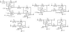
In this paper, an analog circuit equivalent model for the HP memristor is proposed, which is used to study the properties of a real HP memristor. To obtain a flux-controlled memristor as described by Eq. (5), an emulating circuit consisting of four operational amplifiers and three multipliers is designed as shown in Fig. 1.
In Fig. 1, the square-root circuit which is composed of A1, A4, U3A, and U4A, is used to implement the operation in Eq. (5), 
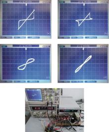
This equivalent circuit emulates the properties of the HP memristor well by transforming conductivity of the memristor into voltage signal, which is more intuitional and convenient to measurement. Since the conductance formula of the HP memristor (Eq. (5)) is derived from the real HP memristor device model (Eq. (2)), the parameters of the two models are one-to-one correspondence, which means that we can obtain k1 and k2 from the given Ron and Roff, and we can derive Ron and Roff through k1 and k2. Some Multisim simulations and the experimental results of the analog circuit-equivalent model are shown as Figs. 2 and 3 to emulate a typical hysteresis loop of the real HP memristor device. In this analog circuit-equivalent model, we set k1 = 1 V and k2 to be varying. The applied voltage is v = vmsin(2π f), where vm = 2 V and f = 150 Hz. In these figures, the horizontal axis is the applied voltage v and the vertical one is the current i, which can be obtained from i = vW(φ ).
From Figs. 2 and 3 we can see that the simulated and experimental volt– ampere characteristics curves of the equivalent circuit in Fig. 1 are exactly in agreement with that of the actual HP memristor.[2]
 | Fig. 1. Equivalent circuit of the flux-controlled memristor characterized by Eq. (5). |
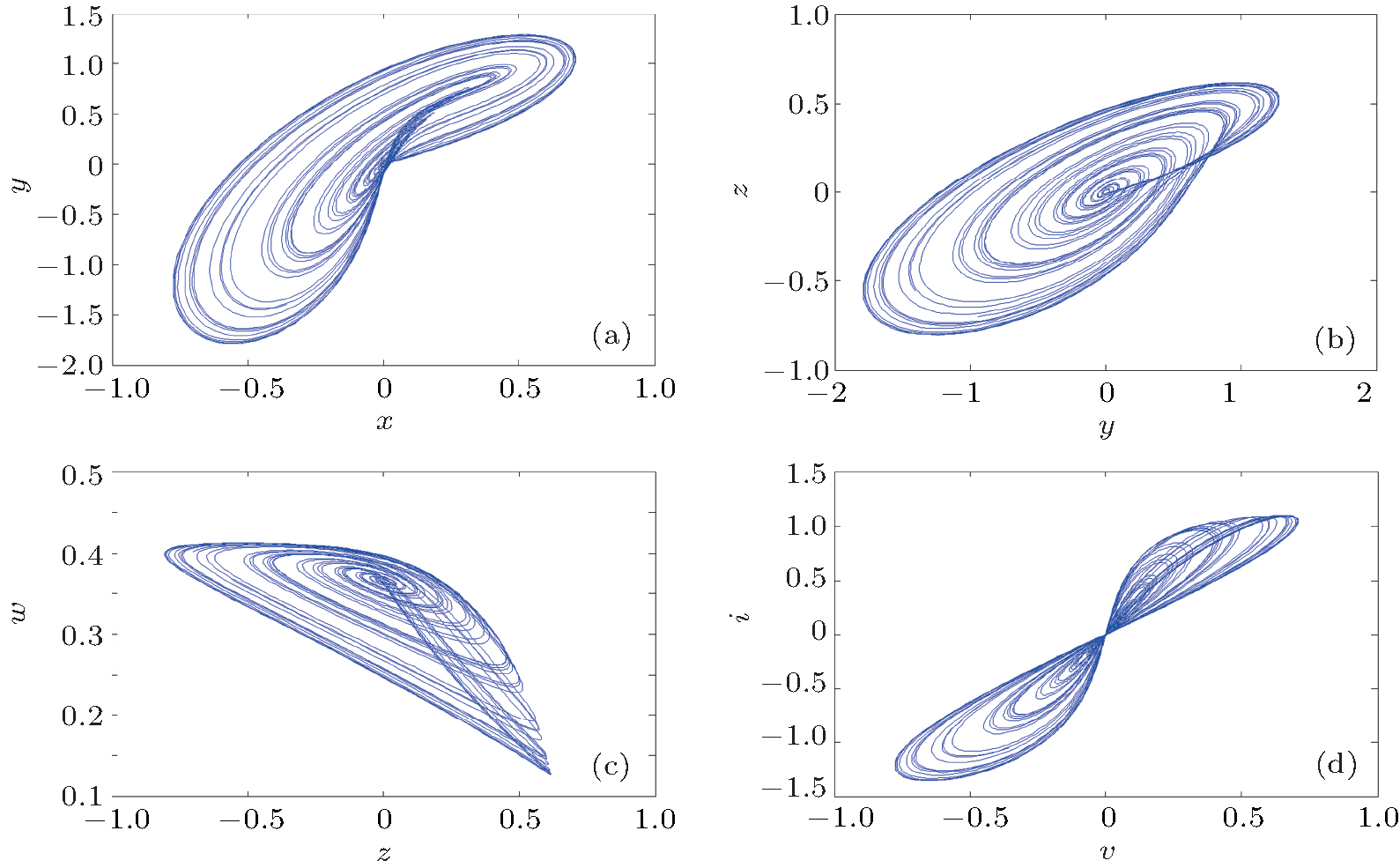
 | Fig. 2. Some Multisim simulations to emulate typical hysteresis loop of the real HP memristor device in conditions of (a) k2 = 11 V; (b) k2 = 5 V; (c) k2 = 3.5 V; (d) k2 = 1.2 V. |
 | Fig. 3. Some experimental results to emulate typical hysteresis loop of the real HP memristor device in conditions of (a) k2 = 11 V; (b) k2 = 5 V; (c) k2 = 3.5 V; (d) k2 = 1.2 V; (e) the experimental equipments. |
Based on the memductance of the realistic HP memristor in Eq. (4) and Chua’ s circuit, a new chaotic oscillator is designed as shown in Fig. 4.
According to Kirchhoff’ s circuit laws, the following differential equations can be obtained:

Let x = v1, y = i3, z = v2, w = φ , α = 1/C1, β = 1/C2, p = 1/L, and γ = G/C2, we can obtain

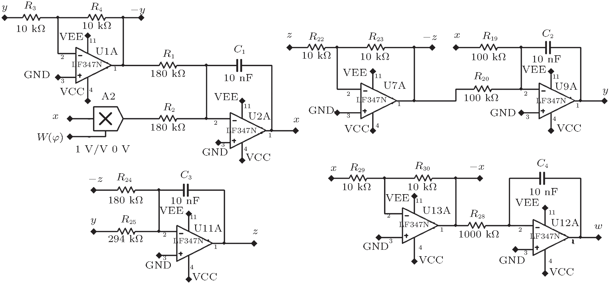
If we set α = 5.6, β = 3.5, γ = 5.5, p = 10, k1 = 1, k2 = 2.4, and k3 = 0, give initial condition as (0.1, 0, 0, 0.1), the chaotic attractor can be shown in Fig. 5.
 | Fig. 4. Oscillation circuit based on an HP memristor model. |
 | Fig. 5. Chaotic attractors ((a), (b), and (c)) and chaotic v– i hysteresis loops (d) of the HP TiO2 memristor in the chaotic oscillation circuit. |
Using the Jacobian method, we can obtain Lyapunov exponents from Eq. (7) as (0.4683, 0.0037, − 0.0093, − 11.8368). The Lyapunov dimension is dL = 2.0391. Figure 6(a) shows the Poincaré mapping on z = 0 and the time domain waveforms of x, y, and w are described in Fig. 6(b), which is aperiodic and pseudo-random. All the above results show that the system we built by using an HP memristor is a chaotic oscillator.
The equilibrium state of Eq. (7) is given by setting s = {(x, y, z, w)| x = y = z = 0, w = constant}. The Jacobian matrix J at this equilibrium set is given as

where

and its characteristic equation is given by

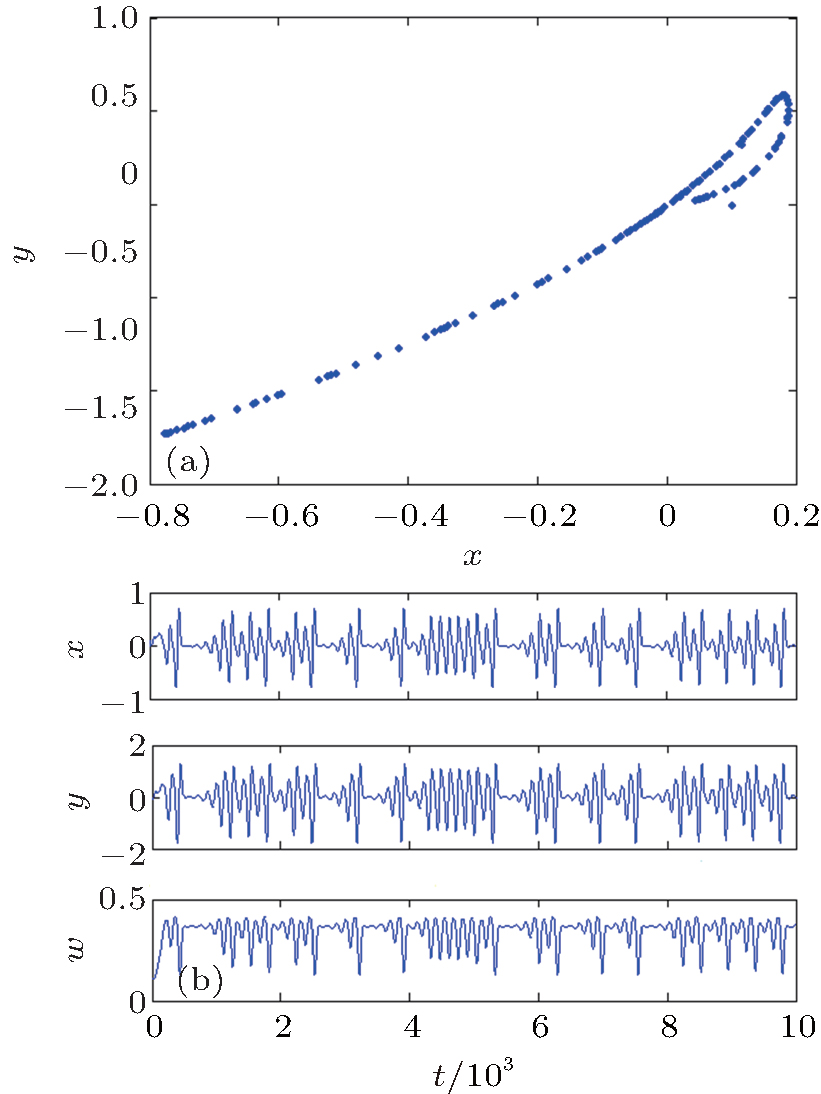 | Fig. 6. (a) Poincaré mapping on z = 0 (projection in x– y plane); (b) the time domain waveforms of x, y, and w. |
Let a0 = 1, a1 = − W − r, a2 = Wr + ap + bp, and a3 = − Wbp − apr. According to Routh– Hurwitz criterion, when

the system eigenvalues (or the real part of the eigenvalue) are negative, the system will be stable. So if the system is a chaos or a hyperchaos one, there should be at least one positive eigenvalue (or the real part of the eigenvalue), which leads to the consequence that not all the expressions of Eq. (10) are positive. For instance, if we set α = 5.6, β = 3.5, γ = 5.5, p = 10, k1 = 1, k2 = 2.4, k3 = 0, and C = 0.1, then Δ 1 = 0.9236, Δ 2 = 134.59, Δ 3 = − 11194, and Δ 4 = 0. In this condition, the equilibrium points are unstable and possess the characteristic of a chaos system.
In order to investigate the rich dynamical behaviors of the proposed circuit, the bifurcation diagrams and Lyapunov spectra are shown below.
By setting β = 3.5, γ = 5.5, p = 10, k1 = 1, k2 = 2.4, and k3 = 0, under initial conditions as (0.1, 0, 0, 0.1), we can obtain the bifurcation diagram as described in Fig. 7(a), which shows the relationship between the variable x and the parameter α , and the Lyapunov exponent spectra with respect to the parameter α in Fig. 7(b) (for better clarity, only the three largest Lyapunov exponents are presented, and the missing ones have smaller negative values). From Fig. 7(a) the dynamical ranges of the limit cycle and chaos can be seen. With the parameter α increasing gradually, figure 7 shows clearly that the periodically forced Chua’ s memristor circuit settles at the periodic state at first, then goes to chaotic oscillation, and the system state changes between the limit cycle and chaos many times in the region of α ∈ [4.5, 6.5]. Some further examples of complex behavior are reported in Fig. 8. In particular, figures 8(a)– 8(c) show the projections of some different limit cycles on the w– y phase plane, and the projections of chaotic attractors generated by the circuit are shown in Fig. 8(d). Parameter values corresponding to the attractors reported in Fig. 8 are indicated in the figure caption.
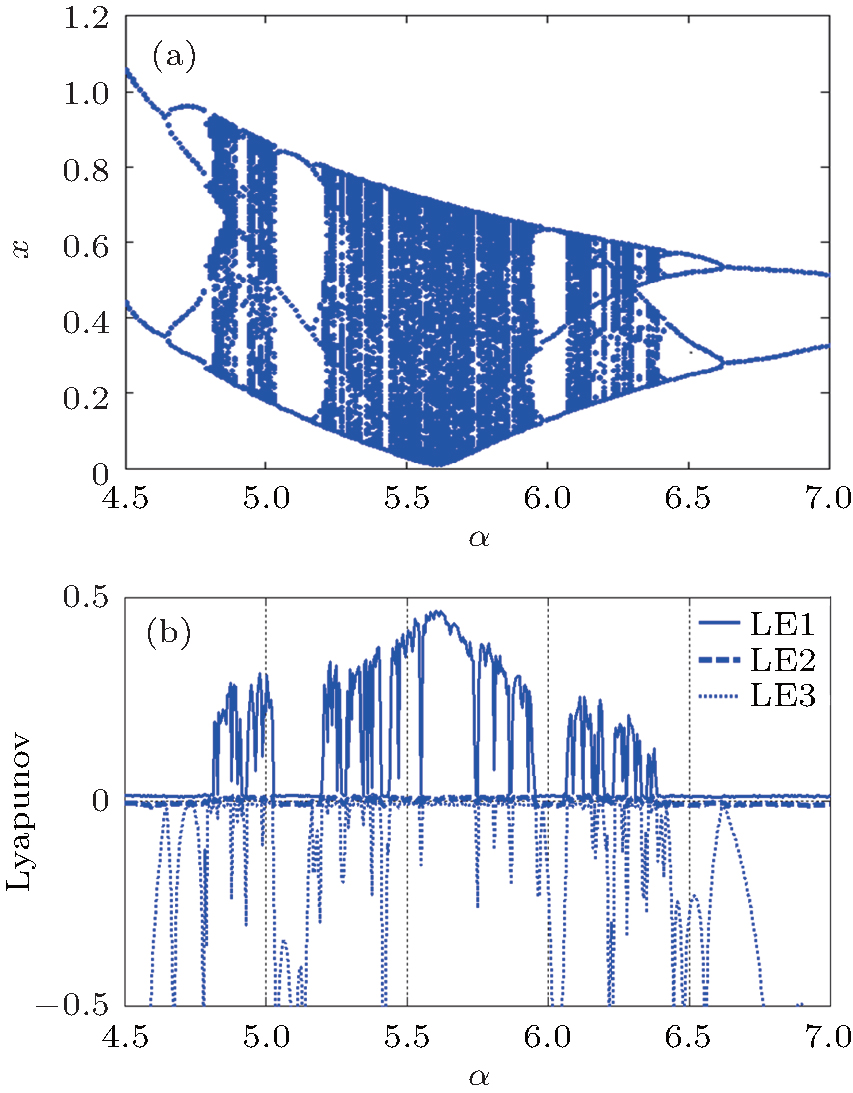 | Fig. 7. (a) Bifurcation diagram and (b) Lyapunov spectrum with respect to α . |
Similarly, the bifurcation diagrams, i.e., the obtained plots of the local maxima of the state variable x are shown in Figs. 9(a) and 10(a). Lyapunov spectra with respect to the other two parameters, calculated using the Jacobian algorithm applied to numerically integrated time series of 6 × 10⁵ samples, are reported in Figs. 9(b) and 10(b). The bifurcation diagrams and the Lyapunov spectra shown in Figs. 9 and 10, respectively, have all been obtained by considering as initial conditions the vector x0 = (0.1, 0, 0, 0.1). The presence of several multistability regions of the system are observed in the regions of p ∈ [9.18, 11] and r ∈ [5.35, 5.624]. In particular, when the parameters meet the conditions of p < 9.18 or r ≥ 5.6242, the system is divergent.
 | Fig. 8. Projections on the w– y phase plane of the attractors observed for four different sets of parameters: limit cycles of different periodicities (a) α = 4.5, (b) α = 4.7, (c) α = 4.9, and chaotic attractor (d) α = 5.6. |
 | Fig. 9. (a) Bifurcation diagram and (b) Lyapunov spectrum with respect to p. |
The circuit has been further investigated by varying the parameter x(0) in the initial conditions the vector x0 = (x(0), 0, 0, 0.1). When we set α = 5.6, β = 3.5, γ = 5.5, p = 10, k1 = 1, k2 = 2.4, and k3 = 0, the bifurcation diagram is described in Fig. 11(a), which shows the relationship between the variable W and the parameter x(0). The corresponding Lyapunov exponent spectra are shown in Fig. 11(b). It is not difficult to conclude that the stability of this memristor oscillator is very sensitive to its initial values. A few small changes in the initial conditions can lead to a great change in dynamical behavior. Different dynamical behaviors of the system along with the parameter x(0) increasing gradually are listed in Table 1.
 | Fig. 10. (a) Bifurcation diagram and (b) Lyapunov spectrum with respect to r. |
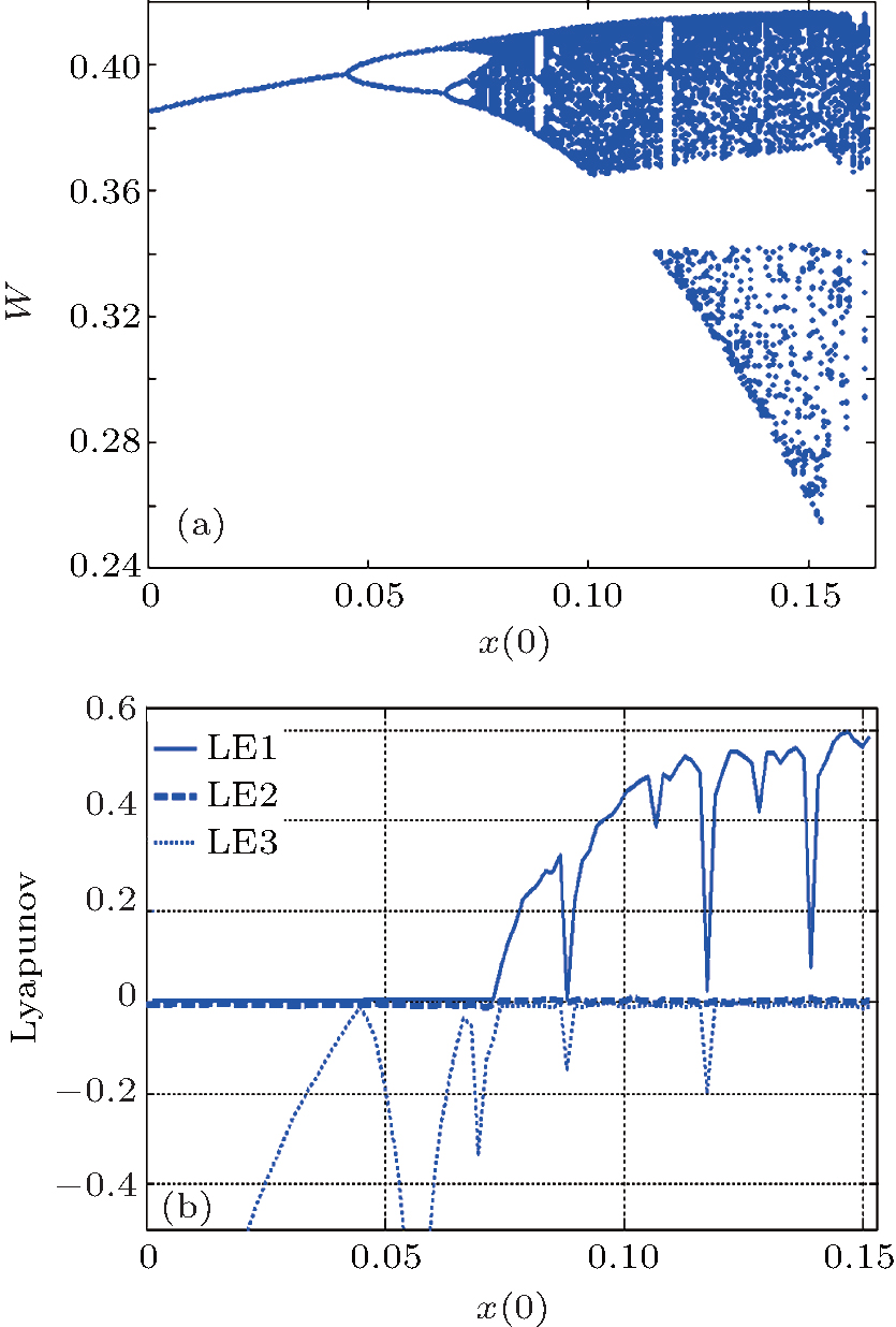 | Fig. 11. (a) Bifurcation diagram and (b) Lyapunov spectrum with respect to x(0). |
| Table 1. Dynamical behaviors of the system with the parameter x(0) increasing gradually. |
In this section, an analog circuit is designed to verify the memristor-based chaotic oscillator (7). For convenience, it is appropriate to do some time scale transformation for Eq. (7). Let τ = Kt, where K is the time scaling. In general, the greater the time scaling factor, the faster the speed of system evolution is.
By using the above transformation rules, equation (7) can be transformed into the following form:

where the time scaling factor is K = 100. Let α = 5.6, β = 3.5, γ = 5.5, p = 10, k1 = 1, k2 = 2.4, and k3 = 0, we can obtain
where 
 | Fig. 13. Chaotic attractors ((a)– (e)) and chaotic hysteresis v– i loops (f) observed by the analog oscilloscope for the TiO2 memristor oscillator from the experimental device. Projections on the w– y phase plane of the attractors observed for four different sets of parameters: limit cycles of different periodicity (g) α = 4.5; (h) α = 4.7; (i) α = 4.9; chaotic attractors (j) α = 5.6. |
The circuit state equations for Fig. 12 are written as

Compare Eq. (12) with Eq. (13) and let their corresponding coefficients be equal, then we will have
Let C1 = C2 = C3 = C4 = 10 nF, the parameters can be obtained as R1 ≈ 180 kΩ , R2 ≈ 180 kΩ , R19 ≈ 100 kΩ , R20 ≈ 100 kΩ , R24 ≈ 180kΩ , R25 ≈ 294 kΩ , and R28 ≈ 1000 kΩ .
Figure 13 shows the experimental results according to Fig. 12 and Fig. 1. A comparison of Figs. 5 and 8 with Fig. 13 indicates that the numerical simulation results are in agreement with practical experimental results. The equipment used in the experiment is shown in Fig. 14.
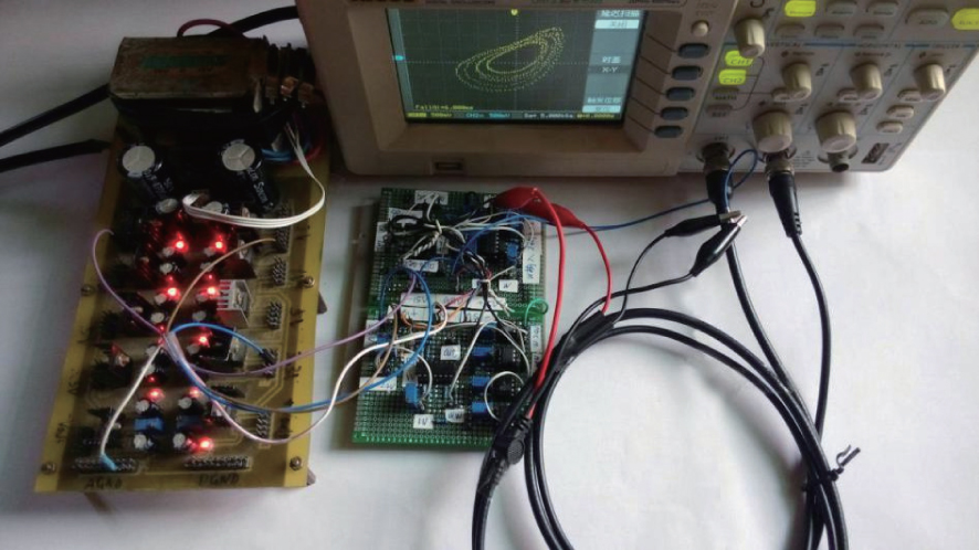 | Fig. 14. Experimental equipment. |
In this paper the practical HP TiO2 memristor model is used to design a chaotic oscillation based on Chua’ s circuit. The oscillator possesses many interesting properties and rich nonlinear dynamics. Compared with other memristor-based oscillators, this oscillator has no transient chaos and is insensitive to initial values in a large range of the initial values, which is an advantage for generating chaotic sequences. To investigate the complex nonlinear dynamics of this memristor oscillator, an equivalent circuit model emulating the memductance of the HP memristor is designed. This equivalent circuit can be used as a memristor emulator, which can act as a real memristor device for breadboard experiments when commercially available memristors do not appear in the near future. It is important for developing memristor application circuits as well as for the other chaos circuits in the community of the memristor for educational purposes.
| 1 |
|
| 2 |
|
| 3 |
|
| 4 |
|
| 5 |
|
| 6 |
|
| 7 |
|
| 8 |
|
| 9 |
|
| 10 |
|
| 11 |
|
| 12 |
|
| 13 |
|
| 14 |
|
| 15 |
|