Transportation-cyber-physical-systems-oriented engine cylinder pressure estimation using high gain observer*
[Li Yong-Fu† , Kou Xiao-Pei, Zheng Tai-Xiong, Li Yin-Guo]
, Kou Xiao-Pei, Zheng Tai-Xiong, Li Yin-Guo]
 |


†Corresponding author. E-mail: laf1212@163.com
*Project supported by the National Natural Science Foundation of China (Grant No. 61304197), the Scientific and Technological Talents of Chongqing, China (Grant No. cstc2014kjrc-qnrc30002), the Key Project of Application and Development of Chongqing, China (Grant No. cstc2014yykfB40001), the Natural Science Funds of Chongqing, China (Grant No. cstc2014jcyjA60003), and the Doctoral Start-up Funds of Chongqing University of Posts and Telecommunications, China (Grant No. A2012-26).
In transportation cyber-physical-systems (T-CPS), vehicle-to-vehicle (V2V) communications play an important role in the coordination between individual vehicles as well as between vehicles and the roadside infrastructures, and engine cylinder pressure is significant for engine diagnosis on-line and torque control within the information exchange process under V2V communications. However, the parametric uncertainties caused from measurement noise in T-CPS lead to the dynamic performance deterioration of the engine cylinder pressure estimation. Considering the high accuracy requirement under V2V communications, a high gain observer based on the engine dynamic model is designed to improve the accuracy of pressure estimation. Then, the analyses about convergence, converge speed and stability of the corresponding error model are conducted using the Laplace and Lyapunov method. Finally, results from combination of Simulink with GT-Power based numerical experiments and comparisons demonstrate the effectiveness of the proposed approach with respect to robustness and accuracy.
Transportation cyber-physical systems (T-CPS) are envisioned to achieve full coordination and optimization of transportation systems via the increased interaction and feedback between the transportation cyber systems and transportation physical systems.[1– 5] Wherein, vehicle-to-vehicle (V2V) communications play an important role in the coordination between individual vehicles as well as between vehicles and the roadside infrastructures.[6– 11] In this context, the V2V-based communication of information on the engine cylinder pressure of the preceding vehicles enables a following vehicle in that platoon to react autonomously to avoid a collision. In addition, information of engine cylinder pressure can be used not only as a feedback signal of closed-loop combustion control for the engine control but also as a cylinder misfire detection signal for engine online fault diagnosis.[12– 16] Therefore, accurate estimation of engine cylinder pressure is of importance within the information exchange process under V2V communications.
This study is motivated by the need for a more accurate and robust observer so that the safety of vehicular traffic flow can be improved under a stimulus through V2V communications related to the engine cylinder pressure. To the best of our knowledge, the existing approaches to obtain information about the engine cylinder pressure can be classified roughly as a direct or an indirect approach. From the direct approach perspective, a variety of high-precision cylinder pressure sensors have been developed. However, the availability of sensors is often limited by their costs, durability, and the installation space in the vehicular engine. Consequently, it is difficult in reality to achieve the control or diagnosis of engine state because of the way that the sensors are installed directly.[16, 17] Therefore, the indirect approach, which can obtain an estimation of cylinder pressure via information about the engine, becomes more attractive because of its low cost and simple structure.
In general, the indirect ways to achieve the cylinder pressure estimation can be categorized as: (i) the Kalman-filter, (ii) cepstrum algorithm, and (iii) sliding mode technique. On the Kalman-filter aspect, Durrra et al.[18] and Ozawa et al.[19] proposed an engine model represented by a time varying linear fist-order differential equation, and the cylinder pressure was reconstructed through a Kalman-filter-based deconvolution algorithm. However, the reconstruction is carried out via the feedforward method, which can deteriorate the accuracy of estimation due to the noise in actual operation. On the cepstrum aspect, Moro et al.[20] and Hamedovic et al.[21] proposed a cepstrum algorithm to reconstruct the cylinder pressure using the vibration signals of engine. However, it is essentially a kind of off-line algorithm and is not suitable for on-board real-time diagnosis. In addition, the influence of road conditions and the vibration of the engine accessories are significant for the accuracy of pressure estimation. On the sliding mode technique, the sliding mode observer (SMO) for cylinder pressure estimation has received wide attention because of its good performance, such as robustness, convergence and accuracy.[22] For example, Veluvolu et al.[23] and Shiao et al.[24] estimated the cylinder pressure using a sliding observer, which could correct the error automatically based on the engine speed error. However, the performance of the observer mainly depends on the accuracy of the engine model, which can be affected by parametric uncertainties, such as efficiency parameter and form factor arising from measurement noise.[16]
The literature review illustrates that the challenge of estimation accuracy for engine cylinder pressure arises from the parametric uncertainties. Hence, motivated by the V2V in T-CPS context, this study seeks to reduce the influence of parametric uncertainties on the estimation accuracy for effective engine cylinder pressure. Specifically, a high gain observer based on the engine dynamic model is designed with the consideration of its inherent robustness properties, as well as the ability to reject model uncertainties.[25– 30] Then, the analyses of convergence, converge speed and stability of the corresponding error model are performed using the Laplace and Lyapunov method. Finally, numerical experiments are carried out to demonstrate the effectiveness of the proposed approach.
The rest of the paper is organized as follows. Section 2 designs the high gain observer based on the engine dynamic model and conducts the analyses of convergence, converge speed, and stability of the corresponding error model. Section 3 performs the simulink-based numerical experiments and compares the performance of the proposed method with those of the second-order SMO and the traditional SMO. The final section concludes this study.
Based on Refs. [16] and [17], a single zone thermodynamics combustion model is used to describe the dynamics of cylinder pressure, where the in-cylinder charge is assumed to be homogeneous and the pressure, temperature, and cylinder charge are uniform within the cylinder. Then, the engine pressure dynamics equation can be written as follows:[16]

where p, γ , 


The term 

where QLHV can be obtained in fuel table, mf (kg) is the injected fuel mass, and

where a and m represent the efficiency parameter and the form factor, respectively, θ , θ 0, and Δ θ are crank angle (° ), initial angle of combustion (° ), and the total angle during the combustion duration (° ).
Moreover, the total cylinder volume V in Eq. (1) consists of the combustion chamber volume Vc and the cylinder work volume Vs, i.e., [16, 17]

where Vc= π D2S/(4(r − 1)), Vs = Apyp, and r, D, S, and Ap are the compression ratio, the cylinder diameter (m), the displacement of piston (m) and the piston cross-sectional area (m2), respectively, and yp is the piston position (m), which is given by[16, 17]
where L and R represent the length of connecting rod (m) and the crank radius (m), respectively. Therefore, the cylinder volume rate can be written as

In order to design the observer, the state of engine cylinder pressure can be defined as

Then, the state-space representation of Eq. (1) can be obtained[31]
where φ 2(x, u) satisfies the Lipschitz condition, i.e., ‖ φ 2(x, u) − φ 2(x̂ , u)‖ ≤ λ ‖ x − x̂ ‖ , and λ > 0 is the Lipschitz constants. Under steady-state conditions, the engine states and parameters are nonzero, so the Jacobi matrix of Eq. ( 8) is as follows:
when the piston moves to top dead center (TDC) and bottom dead center (BDC), 
According to Eq. (8), a high gain observer is proposed for cylinder pressure estimation, i.e.,
where x̂ = [x̂ 1x̂ 2]T represents the observer states and the observer gains h1 and h2 are designed in the following analysis to ensure that the state error is small as desired. The state error is defined as the error between the actual state and the estimation state, i.e., x̃ = x − x̂ . Then, the error model is given based on Eqs. (8) and (10)
where δ (x̃ , u) = φ 2 (x̂ , u) − φ 2(x̂ , u).
For the designed observer (see Eq. (10)), the convergence of estimation errors should be guaranteed, which motivates us to conduct the Laplace transformation of the error model (11) and check whether it is robust to the parametric uncertainties arising from the measurement noise. Based on Eqs. (10) and (11), two kinds of situations are considered as follows.
On the one hand, the error model (11) is addressed under the assumption that the engine dynamic model (1) is a precise description of the object, that is to say, δ (· ) is not considered in Eq. (11), and we obtain

where 
Based on Eq. (12), the observer states x̂ = [x̂ 1x̂ 2]T will approach to the state x = [x1x2]T in finite time if A0 is a Hurwitz matrix. Therefore, the gain h = [h1h2]T needs to ensure that A0 is a Hurwitz matrix, which means the eigenvalues of A0 are negative.
On the other hand, it is necessary to take the influence of δ (· ) to x̃ into consideration since the fluctuation of the parameters a and m will lead to inevitable errors. Therefore, considering the presence of δ (· ), we have
that is
The transfer function of Eq. (14) is
In terms of G10(s), we obtain
If h1 and h2 are large enough, i.e., h1 ≫ 1, h2 ≫ 1, then A(G10(jω )) → 0 and x̃ 1 → 0 can hold.
Similarly, according to G20(s), we have
If h2 ≫ h1, then A(G20(jω )) → 0 and x̃ 2 → 0 is also guaranteed.
Based on the foregoing discussion, considering the combination of the condition h1 ≫ 1, h2 ≫ 1 with the condition h2 ≫ h1, if h2 ≫ h1 ≫ 1, we will have x̃ = [x̃ 1x̃ 2]T → 0, which validates the convergence of the error model (11).
Furthermore, the transfer function of Eq. (15) can be rewritten as

Let

where α 1, α 2 ∈ 
By substituting Eq. (19) into Eq. (18), we can obtain
Hence, we know that G0(s) → 0 if ε → 0. This means that the designed observer is robust to the parametric uncertainties arising from the measurement noise.
Remark 1 According to Eqs. (18)– (20), we can draw a conclusion that error model of the proposed observer is convergent towards zero if the gain parameters are designed reasonably, especially when the condition h2 ≫ h1 ≫ 1 is satisfied. Therefore, the rejection of parametric uncertainties can be achieved. In other words, the proposed observer is robust to parametric uncertainties.
Actually, the error model (11) can be rewritten as

where

The solution of Eq. (21) is

Hence

According to the convergence analysis, we know that A1 is stable. So ∃ ρ , ς > 0 and ρ , ς ∈ 
According to the errors model (11), we choose the Lyapunov function candidate as

Taking the time derivative of the Lyapunov function gives

Based on Eq. (11), the following equation is derived:

In terms of Eq. (26), Ė < 0 if h1 > 0 and 
Remark 2 Based on Eqs. (24)– (26), it can be seen that the stability of the proposed observer depends on the gains h1 and h2. If h1 and h2 are designed reasonably, the stability is guaranteed, and which also means the designed observer can estimate the state variables steadily.
Remark 3 The analyses of Sections 2.3– 2.5 are conducted based on the observer error model (11). Section 2.3, which focuses on convergence, validates that the proposed observer (10) can reject the parametric uncertainties, which means the observer (10) is robust. Section 2.4, which focuses on the convergent speed, verifies that the convergent speed can be adjusted by changing the gains h1 and h2. Section 2.5, which focuses on stability, indicates that the proposed observer (10) can estimate the cylinder pressure with stability, which also infers that the designed observer (10) is stable.
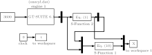
In order to demonstrate the performance of the proposed high gain observer, we perform the simulations with an engine speed of 3600 (r/min). The specific steps are as follows.
Step 1 Build the cylinder engine model using GT-Power, and let the engine work under a large and small load;
Step 2 Incorporate Matlab/Simulink platform with the cylinder pressure model and the high gain observer based on Eqs. (1), (8), (10), and so on;
Step 3 Combine GT-Power with Simulink; and,
Step 4 Test gains h1 and h2 in selected ranges and find the reasonable values to make the errors stable and small.
The parameters associated with the engine are set as: γ = 1.085, θ 0 = − 20° , Δ θ = 40° . The whole Simulink main program is shown in Fig. 1 and the engine specifications are listed in Table 1.
 | Fig. 1. Simulink main program. |
| Table 1. Engine specifications. |
The engine cylinder pressure is estimated from compression stroke to exhaust stroke and the estimation error is defined as e = | (p̂ − p)/p| × 100%. Firstly, the simulation is carried out under small (with the throttle opening angle 5° ) and large load (with the throttle opening angle 75° ) conditions with the gain parameters h1 and h2 based on Eqs. (19) and (26), and with parameters a = 5, m = 3, respectively. The results are shown in Figs. 2– 4.
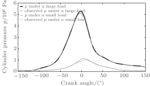
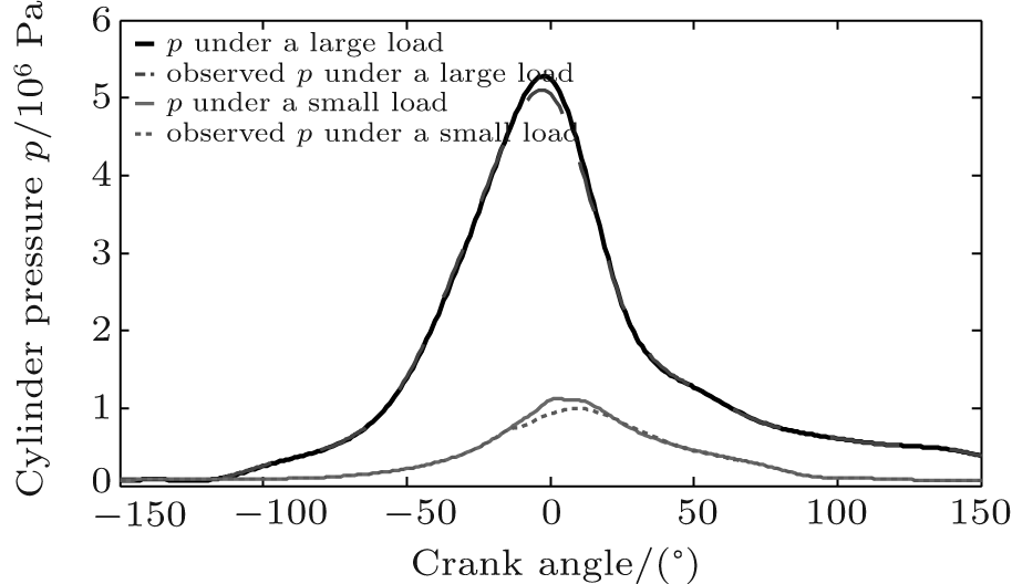 | Fig. 2. Observed cylinder pressure and simulated “ actual” pressure under large and small loads. |
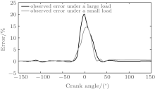
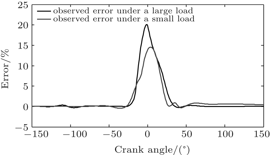 | Fig. 3. Estimation error under large and small loads. |
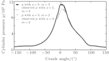
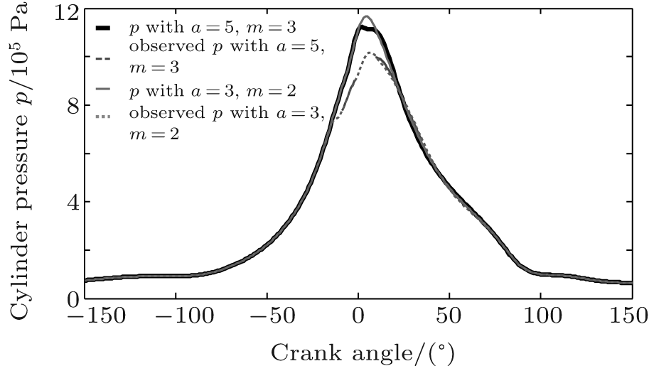 | Fig. 4. Observed cylinder pressure and simulated actual pressure under a small load with different parameter values. |
From Fig. 2 it can be seen that the cylinder pressures estimated by the proposed observer generally approximate to the simulated “ actual” pressure under large and small loads, respectively. In addition, from Fig. 3, we know that estimation errors start to increase before the piston approaches close to TDC and to decrease when the piston takes away from the TDC. This happens because the system states are unobservable at TDC. However, the proposed high gain observer can also keep the estimation error under about 20%.
On the other hand, the comparisons of accuracy around the TDC with the second-order SMO in Ref. [17] and the traditional SMO in Ref. [24] are conducted, and the corresponding observation errors are listed in Table 2.
| Table 2. Error comparison. |
As shown in Table 2, comparatively speaking, the errors for high pressure and low pressure in Refs. [17] and [24] are larger than that in the proposed high gain observer around the TDC region. To account for this phenomenon, a reasonable explanation may be that the second-order SMO in Ref. [17] is unobservable around the TDC region, which results in the pressure error determined mainly by the model error; while the chattering of the observer and the parameters errors in the traditional SMO in Ref. [24] may lead to the error increase. In other words, it shows that the proposed high gain observer has a better ability to avoid the uncertainties from the model. Therefore, the accuracy of the cylinder pressure estimation in proposed high gain observer is guaranteed, even around the TDC regions.
Furthermore, in order to verify the robustness to parametric uncertainties, another simulation is carried out with parameters a = 3, m = 2, and the result is shown in Fig. 4. Figure 4 shows that the accuracy of the designed observer is higher (about 19.8%) than that of the traditional SMO in Ref. [24] (about 30%) even the parameters are changed. That is to say, the robustness of the high gain observer is better than that in Ref. [24].
According to the above discussion, we can draw a conclusion that the proposed high gain observer can not only reject the parametric uncertainties but also has a better robustness and higher accuracy of the cylinder pressure estimation.
To ensure the reliability and accuracy of the cylinder pressure within information exchange under the V2V communications in T-CPS, a high gain observer is designed to reject the parametric uncertainties and improve the estimation accuracy. After the theoretical analyses about convergence, converge speed and stability of the corresponding error model, the proposed observer is proved to be robust and stable and the convergent speed can be adjusted with the gains h1 and h2. Finally, numerical experiments and comparisons with the second-order SMO and the traditional SMO are performed. The results verify the effectiveness of the proposed approach with respect to robustness and accuracy.
| 1 |
|
| 2 |
|
| 3 |
|
| 4 |
|
| 5 |
|
| 6 |
|
| 7 |
|
| 8 |
|
| 9 |
|
| 10 |
|
| 11 |
|
| 12 |
|
| 13 |
|
| 14 |
|
| 15 |
|
| 16 |
|
| 17 |
|
| 18 |
|
| 19 |
|
| 20 |
|
| 21 |
|
| 22 |
|
| 23 |
|
| 24 |
|
| 25 |
|
| 26 |
|
| 27 |
|
| 28 |
|
| 29 |
|
| 30 |
|
| 31 |
|