
Analysis of the third harmonic for class-F power amplifiers with an I– V knee effect
[Zhao Bo-Chaoa) , Lu Yanga) , Wei Jia-Xingb) , Dong Liangb) , Wang Yia) , Cao Meng-Yia) , Ma Xiao-Huab) , Hao Yuea)†  ]
]
]
|
|


†Corresponding author. E-mail: yhao@xidian.edu.cn
The appearance of third-generation semiconductors represented by gallium nitride (GaN) material greatly improves the output power of a power amplifier (PA), but the efficiency of the PA needs to be further improved. The Class-F PA reduces the overlap of drain voltage and current by tuning harmonic impedance so that high efficiency is achieved. This paper begins with the principle of class-F PA, regards the third harmonic voltage as an independent variable, analyzes the influence of the third harmonic on fundamental, and points out how drain efficiency and output power vary with the third harmonic voltage with an I– V knee effect. Finally, the best third harmonic impedance is found mathematically. We compare our results with the Loadpull technique in advanced design system environment and conclude that an optimized third harmonic impedance is open in an ideal case, while it is not at an open point with the I– V knee effect, and the drain efficiency with optimized third harmonic impedance is 4% higher than that with the third harmonic open.
A power amplifier (PA) is a crucial component in the communication system. It is usually at the end terminal of the transmitter, and its output power and efficiency determine the performance of the whole communication system. With the rapid development of third-generation semiconductors, as represented by gallium nitride (GaN) material, the output power of PAs has greatly improved. However, the promotion of efficiency has a great room for improvement.[1– 3] The improvement of efficiency not only benefits from changing more power from direct current (DC) to microwaves, but also from reducing the power which produces heat to increase the performance and lifetime.[4, 5]
Many researchers have made a great effort to improve the efficiency of PAs, among which the class-F power amplifier is a typical method. A C band 60% drain efficiency (DE) PA was implemented in Ref. [6] by tuning the second harmonic. A 70% power added efficiency (PAE) class-F PA was realized through tuning the input waveform.[7] In Ref. [8], the author made a class-F and class-F− 1 PA by shorting the second harmonic, while the third harmonic opening and second harmonic opening while third harmonic shorting achieved 76% and 82% PAE, respectively. A Loadpull technique was used in Ref. [9], and it was found that the best second harmonic impedance was 21.3j, while the best third harmonic impedance was 87.8j, and over 80% PAE was implemented. The author in Ref. [10] found the best harmonic impedance, both in theory and in simulation, and realized a continuous class-F PA with over 70% PAE.
An ideal class-F PA needs short second harmonic and open third harmonic. However, the practice is more complex and it can be found from the above references that the best harmonic impedance is not always in the ideal condition. This paper will analyze in theory how the optimized harmonic impedance changes with the I– V knee effect. This paper is structured as follows. Section 2 introduces the basic principle of class-F PA. The influence of I– V knee effect on the PA performance is analyzed in Section 3. Optimized third harmonic impedance is found with and without the I– V knee effect in Section 4. We compare our results with the Loadpull technique in the advanced design system (ADS) environment in Section 5, and make our conclusion in Section 6.
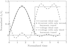
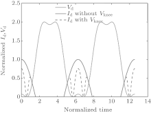
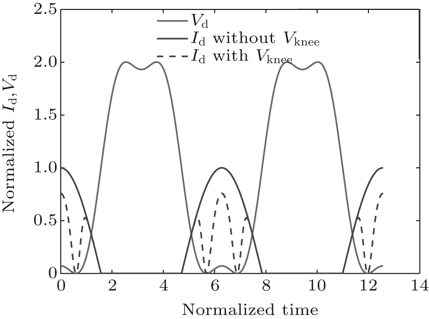
Figure 1 shows drain voltage and current waveform of ideal class-F. It is found that the voltage is a square wave while the current is a half sine wave which has a phase difference of 180° , whether 0 voltage or 0 current will appear at any time. Because the drain current and voltage do not overlap, the transistor will not consume energy, and 100% drain efficiency will then be achieved in the ideal state.
On the other hand, the Fourier expansion of the transistor drain voltage waveform is
where Vdc is the DC voltage, and V1, V3, V5, and V7 are the fundamental and harmonic voltage amplitudes, and w is the angular frequency. The Fourier expansion of the current waveform is
where Idc is the DC component of current, and I1, I2, I4, and I6 are the fundamental and harmonic current amplitudes. It can be seen from Eqs. (1) and (2) that drain voltage components only have odd harmonics while current components only have even harmonics, so harmonics will not consume energy whether harmonic voltage or harmonics current is 0. Therefore, all of the energy is converted to the fundamental, so that the drain efficiency will be 100%. We can also see from Eqs. (1) and (2) that the impedance of even harmonics, which is equal to even harmonic voltage divided by even harmonic current, is 0, and thus the even harmonics are short. While the admittance of odd harmonics, which is equal to odd harmonic current divided by odd harmonic voltage, is 0, the odd harmonics are open.
The class-F PA in an ideal state needs to control all of the harmonics, which is very complex and has less contribution to controlling harmonics higher than the third. Hence, in practice only the second and third harmonics are controlled, [11] the waveform under this condition is shown in Fig. 1 with the dotted lines. We can see from Ref. [12] that if only third harmonic is controlled, then the drain efficiency will achieve 88.4%. The class-F PA in this paper also only considers the second and third harmonics.
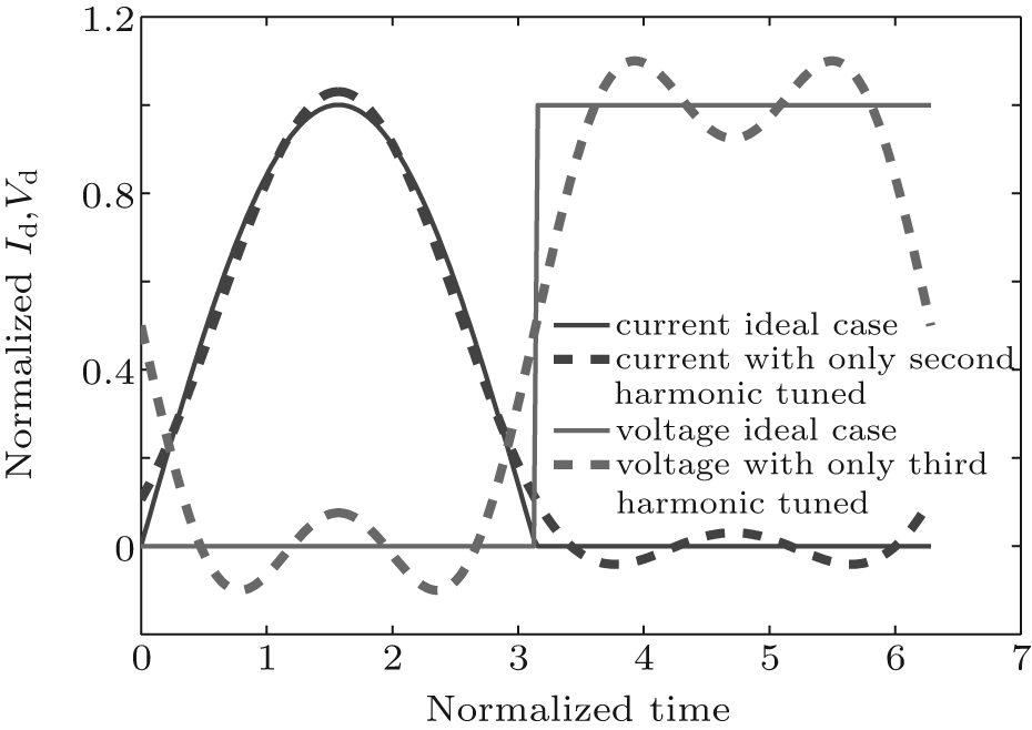 | Fig. 1. Voltage and current waveforms of class-F PA in the ideal case and in the case that only second and third harmonics are tuned. |
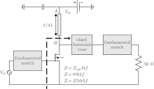
As shown in Fig. 2, it is easy to obtain a short second harmonic when the class-F PA is designed and implemented. A quarter wavelength microstrip line was used at the output terminal of the PA. Because of the ground capacity, the second harmonic has an impedance of 0 at the point A; while a quarter wavelength microstrip line means a half wavelength for the second harmonic, so the impedance at the point B is also short for the second harmonic and the circuit behind has no influence on the point B. Hence, a simple quarter wavelength microstrip line provides a DC bias and implements a short second harmonic at the same time. Although the third harmonic does not attract enough attention in the literature, it is exactly the third harmonic that the class-F PA differs from other PAs. The class-F PA needs a short second harmonic and an open third harmonic. In contrast, a normal PA needs all of the harmonics to be short.
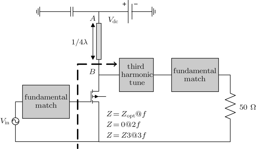 | Fig. 2. Structure of the class-F PA. |
In ordinary research, harmonic impedance is regarded as an independent variable. Different harmonic impedances corresponding to different waveforms have different performance in the class-F PA. However, in the ideal case where the third harmonic is open, the voltage cannot be calculated precisely because of zero current and infinite impedance. We study this problem from another point of view to analyze the influence of the third harmonic on the performance of the class-F PA. Since the third harmonic amplitude is regarded as an independent variable, output power, drain efficiency, and the third harmonic impedance are functions of the third harmonic amplitude. The third harmonic amplitude with optimized performance is exactly determined by a mathematical method and the corresponding impedance is calculated by virtue of Ohm’ s law.
First, we shorten the second harmonic by using a quarter wavelength microstrip line to achieve a second harmonic voltage of 0. The third harmonic voltage is only studied. In order to remove the influence of the DC voltage, all of the harmonic components are normalized to DC, supposing a relative third harmonic voltage amplitude k = V3/V1. Therefore, equation (1) can be rewritten as


only taking the second and third harmonics into consideration. In order to find the maximum value of Vd, we take the derivative of Eq. (3) and let it be 0, and then the solution is
It can be seen that the solution is a function of k, so the maximum value of Vd(Vd, max) is
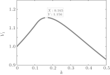
Generally, Vdc is half of the break down voltage, so Vd, max cannot be greater than the breakdown voltage whose value is 2. Let Vd, max be equal to 2, the fundamental voltage V1 will be a function of k. Figure 3 shows how V1 varies with k. Obviously, V1 is 1 without the third harmonic voltage. It can be seen from Fig. 3 that the normalized fundamental voltage amplitude V1 achieves its maximum value of 1.156 when k is 0.165, while the normalized third harmonic voltage V3 is 0.19. We can find from Fig. 3 that a suitable out-phase third harmonic voltage contributes to an improvement of the fundamental voltage, thus improving the output power and the drain efficiency.
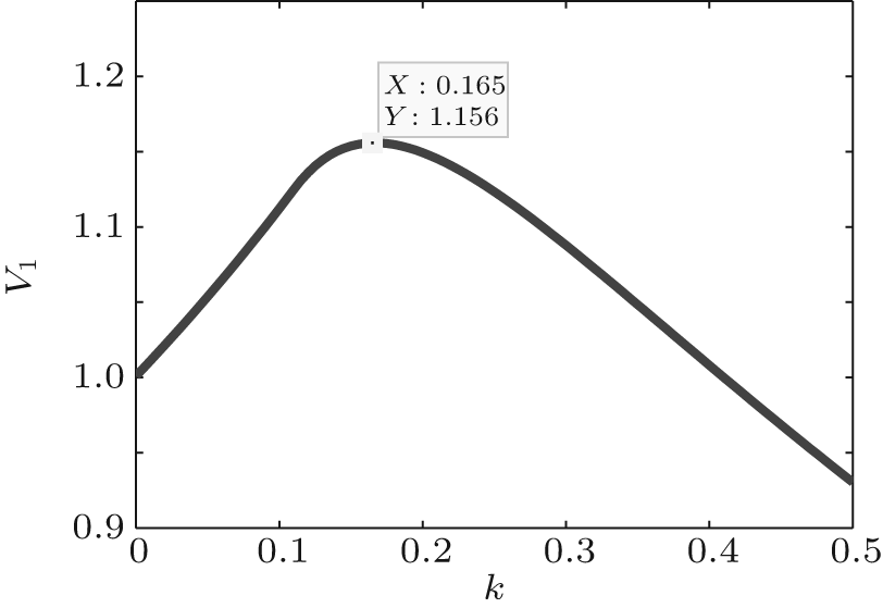 | Fig. 3. Curve between the relative third harmonic voltage k and the fundamental voltage V1. |
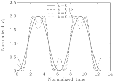
The relationship between the voltage waveform and k is shown in Fig. 4. It can be seen that as k increases, the voltage waveform is closer to a square wave. However, the waveform will have a serious distortion if the value of k becomes too large.
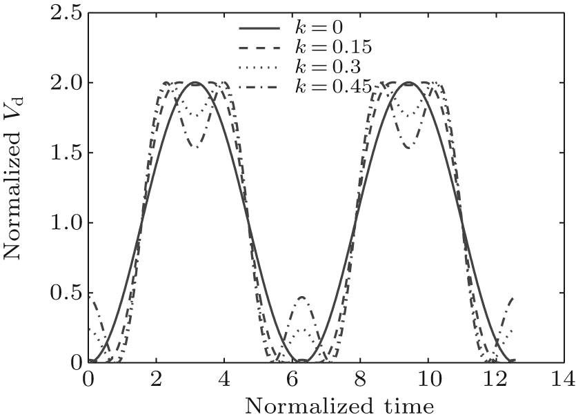 | Fig. 4. Drain voltage waveform at diffident values of k. |
As known to all, the drain current of the ideal class-B PA can be written as

where Iq is the normalized quiescent drain current, and Imax is the normalized maximum radio frequency (RF) current. Since the drain voltage is positive and the input voltage is less than a threshold value, the drain current is also above 0. The drain current almost has the same wave shape as the input voltage, and is not related to the output voltage. However, in practice, when a high-efficiency PA is designed, the I– V knee effect cannot be ignored, so the drain current is not only a function of the input voltage but also a function of the output voltage, which can be corrected by

where Vknee is the voltage at which the drain current reaches 67% of its saturated value, [13] and Vd is given by Eq. (3). The influence of the I– V knee effect on the waveform can be seen in Fig. 5. It can be seen that the current wave will be seriously compressed when Vd is lower than Vknee, so the influence of the I– V knee effect on the PA performance cannot be neglected.
 | Fig. 5. Influence of the I– V knee effect on a waveform. |
According to the Fourier expansion of Eq. (8), because the current waveform is an even function, the DC and the n-th harmonic component of the drain current can be given by


Since the current and voltage are normalized, the output power of the ideal class-B PA is given by

The above equation shows that the fundamental voltage of the ideal class-B V1, idealClass− B is 1, and the fundamental current I1, idealClass− B is 0.5, which are obtained by using the Fourier expansion of Id, ideal. The normalized output power with the I– V knee effect is then given by

The drain efficiency reads
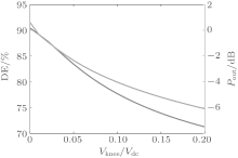
According to Eqs. (7)– (13), both the drain efficiency and the output power have relativity to Vknee, whose relationship is shown in Fig. 6. The drain efficiency and the output power will decrease as Vknee increases. Suppose that Vknee is less than 1/5 of Vdc, then the drain efficiency of the class-F PA will reduce from 90% to about 70%, while the output power will decrease by 6 dB.
 | Fig. 6. Influence of the I– V knee effect on the drain efficiency and the output power. |
As mentioned in Section 3, the third harmonic voltage of the class-F PA has an influence on the fundamental voltage, and the I– V knee effect has an influence on the drain efficiency and the output power. In the following, we first discuss whether the best third harmonic impedance of the class-F PA is open without the I– V knee effect, and then discuss the optimized third harmonic when Vknee has different values.
Without the I– V knee effect, the relative third harmonic voltage amplitude k = V3/V1 is regarded as an independent variable. According to Eqs. (4)– (13), the variations of drain efficiency and output power with k are shown in Fig. 7. When k is equal to 0.17, the drain efficiency will achieve its maximum value of 90.77% and the output power will be 0.63 dB higher than that of the ideal class-B PA. In this situation, we can find that the fundamental voltage amplitude equals 1.157, and the third harmonic voltage amplitude equals 0.197 according to Eqs. (5) and (6). However, the third harmonic current is 0 according to Eq. (10), and the third harmonic impedance is equal to

We can conclude from the above analysis that the optimized third harmonic impedance of a class-F PA is open without the I– V knee effect.
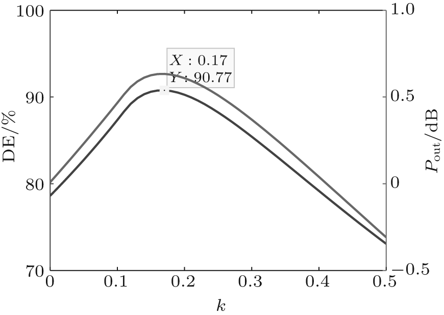 | Fig. 7. Variations of drain efficiency and output power with k without the I– V knee effect. |
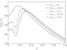
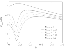
With the I– V knee effect, according to Eqs. (4)– (13), the variations of drain efficiency and output power with k for different Vknee are shown in Figs. 8 and 9. As shown in Figs. 8 and 9, for different Vknee, there is one optimized third harmonic voltage which makes the drain efficiency achieve its maximum value with little power compression. On the one hand, both the drain efficiency and the output power decrease with Vknee; while on the other hand, the optimized relative third harmonic voltage k increases and then the optimized third
 | Fig. 8. Variation of drain efficiency with k for different Vknee. |
 | Fig. 9. Variation of output power with k for different Vknee. |
harmonic impedance changes. The influence of Vknee on the performance of a class-F PA is shown in Table 1.
| Table 1. Optimized third harmonic impedance for different Vknee. |
We can see from Table 1 that as Vknee increases, the drain efficiency and output power decrease, the third harmonic voltage fluctuates a little, and the third harmonic current is no longer 0. Correspondingly, the optimized third harmonic impedance is no longer open. The above analysis leads to the following conclusion: the optimized third harmonic impedance is not open with the I– V effect.
Based on the preceding few chapters, we verify our results by the Loadpull technique in the ADS environment. CGH40010F high-power amplifier model of the CREE is selected. It can be seen from the data sheet that the working frequency is 2 GHz, Vdc is 28 V, the maximum drain current is 3.5 A, and Vknee is 3 V.
We simulate the model with the Loadpull technique where the fundamental matches and second harmonic shortens. In theory and simulation, the optimized third harmonic impedance, the drain efficiency with optimized third harmonic impedance, and the drain efficiency with third harmonic open are shown in Table 2. The real part of the optimized third harmonic in simulation is close to the theoretical value, while the imaginary part in the simulation may be caused by the output capacity of the transistor. It can be seen that the drain efficiency in our simulation is lower than that in theory. This may be caused by a self-hearting effect, a current collapse effect, or other non-ideal effects except for the I– V knee effect. Both in theoretical and simulation results, the drain efficiency with optimized third harmonic impedance is higher than that with the third harmonic open by 3%– 4%.
| Table 2. Comparison of the theoretical results with the simulation results. |
We started with the principle of a class-F PA, regarded the third harmonic voltage as an independent variable, analyzed the influence of the third harmonic on fundamental, pointed out how the drain efficiency and output power vary with the third harmonic voltage with the I– V knee effect, and then found the corresponding third harmonic impedance in a theoretical way with the I– V knee effect. We conclude from the comparison between theoretical results and ADS Loadpull simulation results that: the optimized third harmonic impedance of a class-F PA is open in the ideal case, while it is not at open point with the I– V knee effect, and the drain efficiency with the optimized third harmonic impedance is 4% higher than that with the open third harmonic.
Since other nonlinear effects, such as self-hearting effect and current collapse effect, have a certain influence on class-F performance, we will do further research.
| 1 |
|
| 2 |
|
| 3 |
|
| 4 |
|
| 5 |
|
| 6 |
|
| 7 |
|
| 8 |
|
| 9 |
|
| 10 |
|
| 11 |
|
| 12 |
|
| 13 |
|