High frequency magnetic properties of ferromagnetic thin films and magnetization dynamics of coherent precession*
[Jiang Chang-Juna), b) , Fan Xiao-Longa), b) , Xue De-Shenga), b)†  ]
]
]
|
|


†Corresponding author. E-mail: xueds@lzu.edu.cn
*Project supported by the National Basic Research Program of China (Grant No. 2012CB933101), the National Natural Science Foundation of China (Grant Nos. 11034004 and 51371093), the Program for Changjiang Scholars and Innovative Research Team in University, China (Grant No. IRT1251), and the Specialized Research Fund for the Doctoral Program of Higher Education, China (Grant No. 20130211130003).
We focus on the ferromagnetic thin films and review progress in understanding the magnetization dynamic of coherent precession, its application in seeking better high frequency magnetic properties for magnetic materials at GHz frequency, as well as new approaches to these materials’ characterization. High frequency magnetic properties of magnetic materials determined by the magnetization dynamics of coherent precession are described by the Landau–Lifshitz–Gilbert equation. However, the complexity of the equation results in a lack of analytically universal information between the high frequency magnetic properties and the magnetization dynamics of coherent precession. Consequently, searching for magnetic materials with higher permeability at higher working frequency is still done case by case.
Investigating the dynamic characteristics of magnetization, searching for magnetic materials with high permeability at GHz, and consequently minimizing the size of electromagnetic devices are challenges in developing advanced electronic systems. Higher working frequency and higher integration density are persistent issues in the design of electronic devices, in order to increase the working efficiency and decrease the loss of energy.[1] However, minimization of the size and the energy consumption of electromagnetic devices, such as inductors, which are among the basic electronic devices, is becoming a bottleneck.[2] One of the effective approaches to this problem is to develop magnetic materials with high permeability in the GHz range, [3] which is far beyond the range of traditional high frequency magnetic materials with kHz or MHz working frequency.[4]
The high-frequency magnetic properties in the GHz range are determined by magnetization dynamics: coherent precession and standing spin waves.[5] Coherent precession was first observed in 1946 by ferromagnetic resonance[6– 8] and is closely related to the highly efficient response to microwaves in advanced electromagnetic devices[9– 12] and the high speed magnetization and reversal in high density magnetic recording.[13, 14] The spin wave suggested by Bloch in 1930[15] is intimately connected with the spin-flips, which is a key issue in spintronics[16, 17] and magnonic crystals.[18, 19] Here, we focus on the magnetization dynamics of coherent precession (MDCP), which is related to higher permeability at higher working frequencies of high frequency magnetic materials (HFMM).
HFMM are considered as the magnetic materials with high permeability μ (ω ) and small loss of energy at high working frequencies ω . The higher permeability means a bigger response of the magnetic density B = μ (ω )H to an applied magnetic field H, and the lower loss of energy means a more efficient driven effect of H. Certainly, both permeability and loss of energy are closely related to the dynamics of magnetization M, that is, the dynamic process of magnetization under an applied magnetic field H.
Below kHz, the main dynamic processes of magnetization are coherent rotation and the displacement of the domain wall, [20] which is quite similar to the static situation. Consequently, the permeability μ = B/H is almost constant, where B is determined by M. Therefore, soft magnetic materials with high saturation magnetization Ms are always the best choice. As the eddy loss can be depressed by decreasing the size or thickness and/or increasing the resistivity of the magnetic materials, Fe and FeSi based alloys, amorphous and nanocrystalline alloys as well as spinel ferrites have been widely investigated and used in electrical and electronic devices.[21]
In the MHz range, in order to avoid the huge eddy loss, ferrites seem to be the unique HFMM used in devices.[22] Relaxation and resonance curves can be obtained where a displacement of domain wall or a precession of magnetization may occur. The first well-investigated ferrite is the spinel with cubic symmetry, in which the product of the susceptibility and the resonance frequency is proportional to the saturation magnetization.[23– 25] This means it is impossible to increase the permeability and the working frequency at the same time. In seeking even better HFMM, the hexagonal ferrites are studied, in which the permeability of planar ferrites[26] is larger than that of axial ferrites, even though they have the same crystalline symmetry.
Beyond the 1 GHz range, besides the eddy loss, the significant challenge is to find materials with high permeability. Since the permeability of bulk magnetic materials is mainly determined by magnetocrystalline anisotropy, it is quite difficult to obtain bulk magnetic materials with permeability larger than 20 at the GHz range. Magnetic nanomaterials, such as nanoparticles, nanowires, and thin films, seem to be potential candidates for HFMMs. It has been found that spherical particles, nanowires, and their composites cannot reach the target, for either ferrites or metallic alloys.[27– 31] However, in quasi-two-dimensional systems, such as thin films[32– 40] and flake particles, [41, 42] high permeability in the GHz range has been realized, even if the composition is the same as that of the bulk materials.
Historically, by using the relationship between the magnetic moment m and the angular momentum L in terms of the gyromagnetic ratio γ , the dynamic equation of magnetic moment in a magnetic field H is written as[43]

Experience tells us that the moment eventually moves in the field direction. This fact underlies one of the earliest magnetic devices, the compass. An additional torque has to be introduced that is perpendicular to the precession torque and perpendicular to m. As early as 1935, Landau and Lifshitz (LL) considered the magnetization M in ferromagnetic material as a macro-moment that is a vector with fixed length, and they proposed an equation of the MDCP with damping terms as[44]

where Heff is the effective anisotropy magnetic field, and α L is the LL damping parameter.
In 1946, Bloch introduced two types of dissipative processes to investigate the nuclear magnetic resonance process.[45] One damping mechanism is due to the spin-flip transition, which is characterized by the so-called longitudinal relaxation time τ 1. The second damping mechanism arises from the interaction between different moments, in particular, the decay of their phase relationship as they precess about Heff, which is described by a characteristic transverse relaxation time τ 2. If the relaxation times are the same as τ , the equation of the MDCP can be written as

where χ is the static susceptibility. This equation was first used to describe the ferromagnetic resonance by Yager[7] and can be derived from the LL equations with a small precession angle.[46]
In 1955, Gilbert proposed another damping term to describe damping that may be quite large.[47] The equation of the MDCP with Gilbert damping (LLG) derived based on the Rayleigh dissipation function is given by[48]

where α G is the Gilbert damping parameter. In Eqs. (2)– (4), the first term describes the precession of M about the effective anisotropy field direction, and the second term describes the change of M due to the damping torque. Both the LL and the LLG equations describe the temporal evolution of the magnetization M of which the magnitude | M| remains constant in time.
In 1987, Mallinson wrote, [49] “ All the equations are termed phenomenological because the damping terms do not follow from basic principles. With the increasing academic interest in fundamental issues in magnetism, questions are being asked repeatedly concerning the differences and similarities of damping forms. Although Kikuchi[50] addressed and resolved these questions some thirty years ago, it seems that many of today’ s investigators are unaware of his work.” It has been found that the phenomenological LLG damping seems more reasonable, which is consistent with the origin of intrinsic Gilbert damping studied by Hickey and Moodera in 2009.[51]
This review is aimed at delivering a basic overview of the dynamics of magnetization and their applications in searching for HFMM, as well as the related measurement methods, in addition to providing insight into the dynamics of magnetization in the new frontier of micro-electromagnetic device research. This presentation is organized into three main sections: physics, materials, and related measurement methods. In the first part, we provide a brief review of the theory of high frequency magnetic properties that are described by the products of the permeability and the resonance frequency, which is solved analytically by the LLG equation. In the second part, we describe how to improve the high frequency magnetic properties of magnetic materials according to a newly developed theory: bianisotropy model. In the third part, we summarize the analytic methods for high frequency physical quantities in the thin films.
The key high frequency magnetic property in GHz range, the frequency dependence of permeability, is determined by the MDCP, which is described by the LLG equation. For a ferromagnetic system, if we know its density of free anisotropy energy F, the effective magnetic field Heff in the LLG equation (4) satisfies[52]

where μ 0 is the permeability of free space. By solving the LLG equation (4) with Eq. (5), the frequency dependence of permeability can be obtained. Generally, higher resonance frequency means higher working frequency, and higher initial rotational susceptibility means higher working permeability. Therefore, the high frequency magnetic properties of magnetic materials can be represented as the product of the initial rotational susceptibility and the resonance frequency.
It is known that the initial rotational permeability μ i is the sum of susceptibility χ and 1. Historically, several important simple models show clearly the relationship of the initial rotational permeability and the resonance frequency with the saturation magnetization and the anisotropy field. This relationship points out the ways to improve the high frequency magnetic properties and to find new HFMM. In the following, we summarize the results of these important models by solving the LLG equation (5) without the damping.
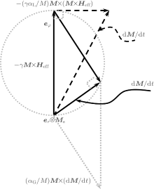
In order to obtain the initial rotational permeability and the resonance frequency, a coherent precession of magnetization is considered wherein the amplitude of magnetization is a constant, that is, M · d M / dt = 0. To satisfy the condition, the damping term in the MDCP has to be written as ∝ M × T, where T is a nonzero vector. Consequently, both T = M × Heff in the LL equation (2) and T = d M / dt in the LLG equation (4) are valid phenomenologically.
Since the introduction of the damping term is artificial, it is important to answer whether the LL or LLG equation is more reasonable. According to the idea of Kikuchi[50] and Mallinson, [49] the terms in the LL and LLG equations can be plotted in a vector frame as shown in Fig. 1. It is found that when increasing the damping constant, the damping torque term in the LLG equation rather than in the LL equation is always smaller than the precession torque term. This is why the LLG equation is more popular to describe the MDCP. Note that it should not be forgotten that the Gilbert formalism is not unique; to quote Kikuchi, “ a myriad conceivable forms” of damped gyromagnetic precession equations may be imagined.[49]
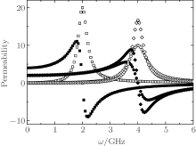
As the LLG equation is a nonlinear differential equation, it is difficult to obtain an analytical solution even if we know the effective anisotropic field, the damping, and the saturation magnetization. However, a numerical solution of the LLG equation, shown in Fig. 2, indicates that the precession torque term determines the main high frequency characteristics, the resonance frequency and the amplitude of permeability, but the damping torque term mainly changes the widths of the resonance peaks. This means a guiding idea of the high frequency characteristics can be obtained by neglecting the damping term.
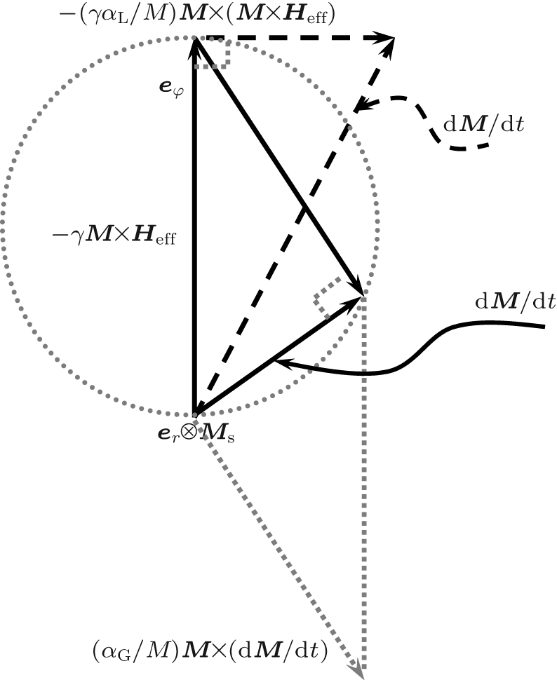 | Fig. 1. Vector diagram of the LL equation (dash line) and the LLG equation (solid line). |
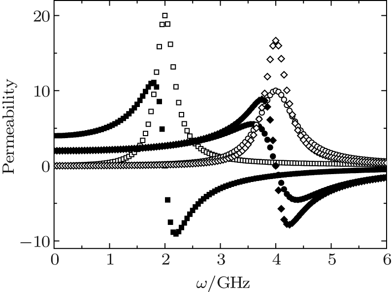 | Fig. 2. The frequency dependency of permeability with γ Ms = 8 GHz. Solid and open symbols represent the real and the image parts of the permeability. Square represents α = 0.1 and γ Heff = 2 GHz, circle represents α = 0.1 and γ Heff = 4 GHz, and diamond represents α = 0.06 and γ Heff = 4 GHz. |
Consider the simplest ferromagnet, a single domain spherical crystal with a uniaxial magnetocrystalline anisotropy. The density of the anisotropy energy is

where K0 and K1 are anisotropy constants, and θ is the polar angle away from the easy axis. By using Eq. (5), the effective anisotropy field can be written as

for a small angle precession, θ → 0, Heff = HK = 2K1/μ 0Ms is constant. From the LLG equation (4) without damping, the product of the initial rotational permeability μ i and the resonance frequency fr satisfies

where μ i = 1 + Ms/HK, and fr = γ HK. If the sample is composed of a series of single domain spherical crystals without interaction, supposing a randomly distributed anisotropic field, the famous Snoek’ s law[23, 24] can be obtained

It is found that the product of the initial rotational susceptibility and the resonance frequency is proportional to the saturation magnetization. This means that the only way to seek better high frequency magnetic materials is to fabricate materials with higher saturation magnetization.
Note that, although equation (8) or (9) well explains the high frequency characteristics of the ferrites with uniaxial anisotropy as well as the cubic anisotropy, the law has not been proven experimentally yet because of the difficulty of deriving the frequency-dependent rotational permeability and the complexity of angle-dependent resonance frequency for a real ferromagnet.
Besides the uniaxial anisotropy in the hexagonal ferrites, another typical magnetocrystalline anisotropy is the planar anisotropy, which corresponds to the planar ferrite called ferroxplana. The ferroxplana was first reported by Jonker et al., [53] and its density of anisotropic energy is[54]
With a process similar to Snoek’ s law, the product of the initial rotational permeability and the resonance frequency for a single domain spherical planar crystal can be derived as
where

and φ is the azimuthal angle.
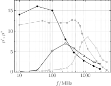
Compared to Snoek’ s law, in addition to the saturation magnetization, the anisotropy field has a strong effect on the high frequency properties. This is why Co2Z has much better high frequency properties compared with the spinel ferrite, as shown in Fig. 3.[53, 55] However, to change the magnetocrystalline anisotropy field of a crystal, we have to change the symmetry of the crystalline field and/or the content and distribution of elements in the magnetic materials. This implies the same difficulty as Snoek’ s law when searching for different magnetic materials with better high frequency properties.
If the single domain crystal is a non-spherical particle, the shape anisotropy is significant. In 1948, Kittle[46] considered an ellipsoid with principal axes parallel to the x, y, z axes of the Cartesian coordinates. The static magnetic field H is along direction z, and the radio frequency (rf) field h is along the x axis. The effective magnetic field components inside the materials are
where Nj and Mj (j = x, y, z) are the demagnetization factor and the component of magnetization along direction j, respectively. By substituting these components for Heff in the LLG equation (4) with α G = 0, the initial rotational permeability and the resonance frequency are obtained as


Considering some special cases (sphere, infinite circular cylinder, plane), it is found that only the plane with Nx = Ny = 0 and Nz = 1 has a better product of the initial rotational permeability and the resonance frequency, compared with Snoek’ s law. In 1999, Acher showed that the product of a thin film with in-plane uniaxial magnetic anisotropy (IPUMA) is[33]

In 2002, Buznikov[39] showed a similar product for a thin film with out-off anisotropy, and in 2000, Acher gave an integrated relationship beyond that.[56] Now, the key task is to find the underlying relation between Snoek’ s law (8), the ferroxplana (11), and Acher’ s law (15).
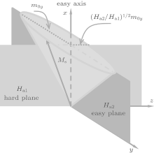
It is known that the anisotropy of a ferromagnet can be the magnetocrystalline anisotropy, the shape anisotropy, the stress anisotropy, the exchange interaction, or their mixture. Therefore, it is difficult to obtain the high frequency properties because of the complexity of the effective magnetic field. However, no matter what the precise origin of the anisotropy is, the precession of the magnetization around the easy axis in any magnetic material can be determined by the anisotropy magnetic fields acting on the magnetization. Consequently, suppose the magnetization along the x axis feels different anisotropy fields Ha1 and Ha2 in hard plane (xz) and easy plane (xy), respectively, as shown in Fig. 4. When a microwave magnetic field h with angular frequency ω is applied in the y direction, if a small magnetization deviation from the easy axis occurs, the LLG equation with no damping term in a component form is


From Eqs. (16a) and (16b), it is easy to obtain the initial rotational permeability and the resonance frequency in the y direction


Combining Eqs. (17) and (18), the product of the initial rotational permeability and the resonance frequency satisfies[32]
which characterizes the high frequency properties of the bianisotropy magnetic materials.
Compared with Snoek’ s law, the bianisotropy model indicates a new way to increasing the high frequency magnetic properties by adjusting the effective fields Ha1 and Ha2. The objective is to find magnetic materials in which the precession of the magnetization is an elliptical cone trace rather than a circular cone trace as in Snoek’ s model. An elliptic dynamic equation of magnetization components can be found by squaring Eqs. (16a) and (16b)
where 
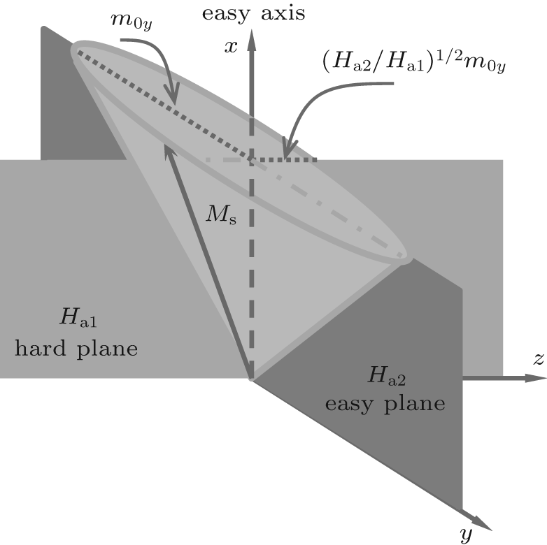 | Fig. 4. Scheme of the bianisotropy model.[32] |
From Eq. (19), it is easy to derive the formulae for the polycrystalline bulk materials represented by Snoek’ s law with uniaxial or cubic magnetocrystalline anisotropy field as Ha1 = Ha2 = HK, for the planar ferrites with Ha1 = HKθ (anisotropy field in θ direction) and Ha2 = HKφ (anisotropy field in φ direction), as well as for the in-plane uniaxial thin film described by Acher’ s law with Ha1 = Ms (out-of-plane demagnetization field) and Ha2 = Ha (in-plane anisotropy field). Clearly, the bianisotropy model is more universal to describe the high frequency characteristics of magnetic materials.
As the thin film is a bianisotropy system, significant progress has been made on the GHz magnetic properties with high working frequency and high permeability suitable for applications such as inductors, transformers, and other magnetic devices.[57– 62] Based on Eq. (19), it is found that the magnetic anisotropy is a key factor to adjust the high frequency characteristics for certain soft ferromagnetic thin films in which the saturation magnetization is fixed. Desirable high frequency characteristics with adjustable IPUMA are typically obtained after post-deposition magnetic heat treatments[63– 66] or by depositing thin films at 300– 600 ° C for nanocrystallization.[67– 71] In order to avoid the high temperature post heat treatment that complicates the processing of the devices, several techniques have been employed to realize adjustable high frequency characteristics of thin films; among the techniques are in-situ sputtering deposition with magnetic field, [72– 74] doping transition metals, [75– 77] oblique sputtering, [78– 87] depositing multiple layers, [38, 88– 91] covering with a layer of antiferromagnetic materials, [92– 97] and electric field induction.[98– 103] Here, we report a different approach to induce the IPUMA of magnetic films and to obtain better GHz magnetic properties.
In a single ferromagnetic thin film, the familiar shape anisotropy and exchange interaction favor alignment of magnetization with the film plane. The IPUMA of a polycrystalline ferromagnetic film formed by magnetocrystalline, dipole interaction, stress, and their cooperation can be adjusted by introducing a two-phase nanostructure, sputtering deposition with magnetic field, gradient sputtering or gradient-composition deposition, or oblique deposition, as well as their mixture.
In ferromagnetic metal films, nanocrystallization with doping nonmagnetic elements, such as CoM (M = Zr, Hf, TaN), [104– 106] FeM (M = B, Hf, Zr), [107– 110] FeCoM (M = B, Hf, Zr), [111– 113] are effective approaches to obtain IPUMA, which utilizes the dipole interaction between two phases with different magnetizations.[114, 115] In addition, the magnetic anisotropy of a granular system with doping nonmagnetic oxide materials, such as SiO2, [116] TiO2, [117] Al2O3, [118] is controlled by changing the effective magnetocrystalline anisotropy of the magnetic nanoparticles. For ferrite films, there is no significant effect to induce magnetic anisotropy by the above approaches, which can be obtained by applying a magnetic field during depositing or post-annealing.[119, 120]
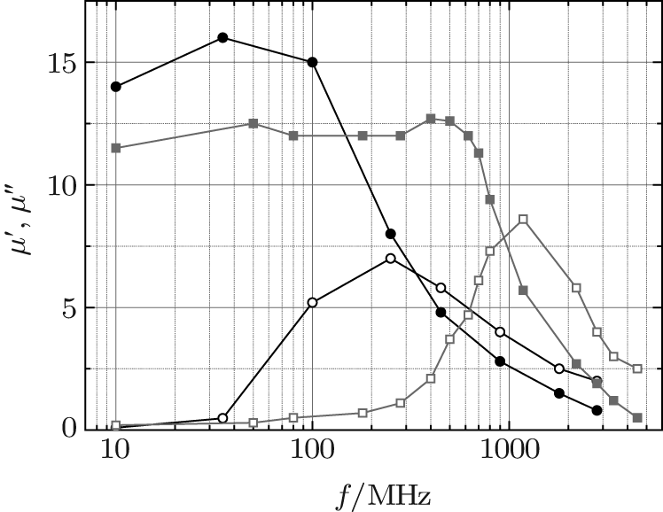
The simple method to adjust IPUMA is sputtering deposition under a magnetic field. By applying an external magnetic field during the deposition, all moments tend to align along the direction of the magnetic field, which forms an easy magnetization axis. The Co100− xZrx (40 nm) (x = 0, 4, 9, 12 at.%) films with IPUMA were obtained on Si substrates by rf magnetron sputtering at room temperature, [121] where a magnetic field of about 600 Oe was applied parallel to the film plane. Ge et al. reported that excellent soft magnetic properties are achieved in a wide metal-volume-fraction (x) range for the as-deposited (Fe65Co35)x(SiO2)1− x granular films fabricated by this method.[122] The magnetic hysteresis loop of the sample exhibits good IPUMA with an anisotropy field around 60 Oe. The real part of permeability μ ′ is constant at 170 below 1.3 GHz, while the imaginary part of permeability μ ″ is visible for f > 1 GHz.
Normally, the IPUMA field is low (< 100 Oe) after sputtering deposition with an external magnetic field. Hence, it is difficult to prepare ferromagnetic films with resonance frequency in excess of 3 GHz. Li et al. employed a gradient sputtering method to enhance the anisotropy field of FeCoHf films.[77] The FeCo target was faced to the geometric center of the samples, while the geometric center of the doping target Hf was outside of the samples. Thus, a geometrically uniform FeCo composition was doped with a radically increased Hf content. A high ferromagnetic resonance frequency fr up to 7.18 GHz and cut-off frequencies fcut − off between 4.35 GHz and 4.93 GHz were achieved. Ong’ s group investigated the behavior of the temperature dependence of magnetic anisotropy in FeCoHf thin films fabricated by gradient-composition deposition.[123] They found that the effective IPUMA field was increased as the temperature raised from 300 K to 420 K.
The IPUMA induced in magnetic thin films by oblique deposition was discovered in 1959 by Knorr[124] and Smith[125]et al., who showed that the magnetic anisotropy (even at zero applied field) can be induced in iron and permalloy films by making the metal vapor hit the substrate at an oblique deposition angle. First, the oblique deposition tends to produce a low-density film with columnar grains that are tilted toward the source, yielding an anisotropic easy axis in the plane of incidence. Second, in the plane of the film, oblique deposition tends to produce grains that are elongated perpendicular to the plane of incidence. This effect is primarily due to the fact that shadowing effects can break the film continuity more easily in the deposition direction than in the perpendicular in-plane direction. By changing the oblique deposition angle, for the Fe– SiO2 multilayer, the ferromagnetic resonance frequency can be effectively tuned from 1.7 GHz to 3.5 GHz.[83] Hirata et al. investigated the Ru(5 nm)/FeCoB (200) film with suitable conditions by the oblique sputtering.[126]
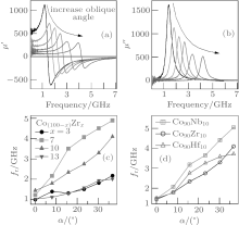
Our group developed an oblique sputtering method to form a two-phase nanostructure with which adjustable IPUMA field[114] and resonance frequency in Co-based films[76] were achieved. A Co target, on which several (Nb, Zr) chips were placed in a regular manner, was used. Thin films were deposited with an oblique angle between 0° and 38° , and the direction of the in-plane easy axis was found to be perpendicular to the deposition direction. The increase of the IPUMA field with increasing oblique angle resulted in a significant enhancement in the resonance frequency of these films, as shown in Fig. 5. The IPUMA field of the Co– Nb film with an oblique angle of 38° is about 280 Oe, which is almost seventeen times larger than 15 Oe for the film deposited without an oblique angle. The fr can attain a value as high as 4.9 GHz and the real part of permeability remains at 40 up to 4 GHz.
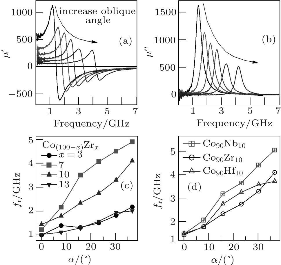 | Fig. 5. Modification in the high frequency properties by adjusting the deposition oblique angle: (a) real and (b) imaginary parts of the permeability of the Co90Zr10 thin film; plots of the resonance frequency fr against the oblique angle for (c) CoZr and (d) CoNb with different doping concentrations.[76] |
Compared to single-layer thin films, multilayer films have more origins of IPUMA because the existence of interfaces and the interaction between layers. The interface anisotropy, [127] the exchange coupling anisotropy in ferromagnet (FM)/antiferromagnet (AFM)[128] and ferromagnet/ferromagnet, [129] and the dipole interaction between different magnetic layers may introduce extra contributions to the IPUMA of a ferromagnetic layer in a multilayer film. The interface anisotropy energy is in-plane isotropy, which is somehow like the demagnetization energy. Thus, the interface anisotropy can increase the resonance frequency without decreasing the in-plane permeability of the films. In other words, Acher’ s law can be enhanced by introducing the interface energy.[38] In the FM/AFM multilayer systems, the exchange coupling between AFM and FM spins will introduce the unidirectional anisotropy and the rotatable anisotropy.[130] The exchange coupling and dipole interaction between FM layers can also result in a change of the IPUMA.[131]
In the FM/AFM system, the exchange bias between FM and AFM has been extensively studied in the past few decades because of their application in spin-valve-based sensors in the hard disk industry as well as the exchange bias’ s intriguing physical origin. When introducing an exchange bias field HE by an effect of FM– AFM coupling, the effective IPUMA of the FM layer is the sum of the exchange bias field and the IPUMA field HK of the FM layer without the exchange bias. As a result, the resonance frequency can be written as follows:

where Ms is the saturation magnetization of the FM layer. Equation (21) indicates that the resonance frequency can be increased when the exchange bias field is parallel to the IPUMA field HK. In the FeNi/FeMn exchange biased system, [132, 133] the FeNi/FeMn bilayers exhibit an exchange bias field HE = 37 Oe and an enhanced coercivity Hc = 6 Oe, while in the single FeNi layer, an anisotropy field HK = 5 Oe and a coercive field Hc = 3 Oe are observed. The imaginary part of permeability shows that the effect of the bias layer significantly increases the resonance frequency from 0.5 GHz of the unbiased sample to 1.8 GHz of the biased sample. Acher et al.[134] observed a large resonance frequency 2.7 GHz for the thinnest FM layer (thickness 15 nm) by changing the thickness of the FM film in the FeNi/IrMn system, which results from the largest exchange bias field.
In FM/nonmagnetic materials (NM) multilayer films, the interface anisotropy and exchange coupling between FM layers also affect the high frequency characteristics. The interface anisotropy is out-of-plane anisotropy for a positive interface anisotropy constant or in-plane anisotropy for a negative interface anisotropy constant. Hence, the FM/NM interface with the negative interface anisotropy Ku constant is employed to extend Acher’ s law, which can be revised as[38]
where t is the thickness of each ferromagnetic layer. For instance, [38] in order to maintain the saturation of magnetization and to eliminate the effect of the exchange interaction between CoZr layers, a series of (CoZr/Cu)n multilayer films was fabricated in which the thickness of the total CoZr layers is 180 nm and each Cu layer is 20 nm. The relationship between Acher’ s law and the number of periods n is linear rather than a constant. Besides the interface anisotropy, a stronger interlayer exchange coupling results in higher resonance frequencies in the CoNb/Ta multilayer system.[131] The thickness of each CoNb layer is 11.5 nm and the thickness of the Ta interlayers is changed for different samples, which affects the exchange coupling between adjacent CoNb layers. It was found that the values of fr and HK can be adjusted from 6.5 GHz and 520 Oe to 1.4 GHz and 12 Oe by increasing the Ta thickness from 1.8 nm to 8.0 nm, with small changes of damping parameters.
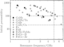
We summarize the high frequency properties of Co- and Fe-based thin films in Fig. 6. The plot of the initial rotational permeability against the natural resonance frequency reveals two results. 1) The higher the magnetization, the higher the permeability, and permeability exceeding 20 can be achieved in 1– 5 GHz range for most Co- and Fe-based thin films. 2) Finding thin films exceeding 100 above 5 GHz is still a challenge.
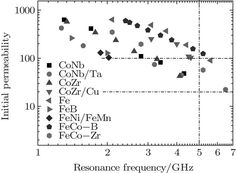 | Fig. 6. The high frequency characteristics of Co- and Fe-based thin films and multilayers measured at room temperature. |
Traditionally, the magnetization direction in ferromagnetic materials is controlled directly by the combination of the anisotropic field of the magnetic material itself and an external magnetic field or a current that produces a magnetic field. Recently, controlling magnetic anisotropy or magnetization direction in a ferromagnetic material directly by applying an electric field rather than a current has become a main issue in the fields of spintronics and multiferroics. Multiferroic materials and devices have attracted intensified interest recently due to the demonstrated strong magnetoelectric (ME) coupling in new multiferroic materials and devices with unique functionalities and superior performance.[135] Strong ME coupling at GHz frequencies and the combined high permeability and high permittivity in multiferroic composite materials provide great opportunities for future compact, light-weight, and power-efficient voltage tunable rf/microwave devices.[136]
The three main factors of electric-field-modulated magnetization are charge, strain, and exchange biased mediation. So far, the tuning of magnetization for microwave magnetic devices is induced by strain, and the in-plane magnetic anisotropy is manipulated through biaxial stress originating from piezoelectric and magnetostrictive effects. The voltage-induced effective anisotropy field can be expressed as[102]

where λ s is the magnetostriction constant of the magnetic material and σ E is the electric-field-induced biaxial stress. In 2009, Sun’ s group reported that strong magnetoelectric coupling (ME) and giant microwave tunability were demonstrated by an electrostatic field-induced magnetic anisotropic field change in Fe3O4/PZT multiferroic heterostructures.[137] A high electrostatically tunable ferromagnetic resonance (FMR) field is shifted up to 600 Oe. For FeGaB film with high magnetostriction, an applied electric field produces a large tunable frequency range, Δ f = 7.5 GHz, at low bias field Hb = 650 Oe.[138]
Due to the strain effect induced by an electric field, the magnetic anisotropy of the ferrite film can be tuned, which avoids the high temperature thermal treatment.[139– 141] Recently, we obtained linear electric modulation in anisotropy energy that arises from a strain-mediated magnetoelectric coupling across an interface.[142] We traced this effect back to the piezoelectric control of magnetic anisotropy. By adjusting the intensity of the electric field applied across the sample, the anisotropy direction and the magnitude of the Ni0.46Zn0.54Fe2O4/Pb(Mg1/3Nb2/3)O3-PbTiO3 film were found to be controlled, respectively. In addition, the natural resonance frequency of the Co film deposited on the Pb(Mg1/3Nb2/3)O3-PbTiO3 substrate can be modulated by an electric field.[143] Voltage-controlled magnetization switching was also found in an FeNi/piezoelectric actuator hybrid structure, where a film-thickness dependent in-plane magnetization easy axis rotation angle was observed and explained by the variation of magnetostriction.[144]
Since the MDCP was first investigated by FMR, by means of which the anisotropy field and the damping can be derived from the resonance frequency and the line width, respectively, [46, 145– 155] the utility of FMR has been enhanced by using a vector network analyzer (VNA).[156– 164] In order to obtain the permeability spectrum of thin film (PSTF), it was suggested that a wideband measurement can reveal the frequency dependence of permeability.[165– 171] After that, the measurement of the PSTF has been developed both in design[172, 173] and in static magnetic field modulation.[174, 175] More recently, the electric detection of FMR based on the spin rectification effect (SRE) was suggested, by which the dynamics of magnetization has been observed even at large cone angle.[176]
When a high frequency alternating magnetic field is applied to a substrate, certain resonance effects are observed at particular values of frequency and magnitude of the field, such as FMR occurring in ferromagnetic materials and electron paramagnetic resonance (EPR) (also called spin resonance (ESR)) occurring in non-ferromagnet materials except in diamagnetic materials. FMR associated with the motion of the total electron moment of the ferromagnet precesses about the direction of the static magnetic field, and the energy is absorbed strongly from the rf transverse field when its frequency is equal to the precession frequency.[145]
The basic setup for an FMR experiment is a microwave resonant cavity with an electromagnet. The resonant cavity is fixed at a frequency in the super high frequency band. A detector is placed at the end of the cavity to detect the microwaves. The magnetic sample is placed between the poles of the electromagnet, and the magnetic field is swept while the resonant absorption intensity of the microwaves is detected. When the magnetization precession frequency and the resonant cavity frequency are the same, the absorption intensity increases sharply, which is indicated by the decrease of the intensity at the detector. FMR is complicated by eddy-current effects in the sample. At the frequency of about 10 GHz, the eddy-current shielding of the interior of the specimen is so nearly complete that the depth of penetration of the alternating field is only about 100 nm or 300 atom diameters.[146]
The resonance frequency at a saturated field can reveal not only the g factor but also the effective anisotropy constants, or strictly the anisotropy fields HK. If the applied field is not large enough to saturate a ferromagnetic sample, resonance phenomena may still occur. Various nonuniform resonance modes may arise, by which different parts of the sample are magnetized in slightly different directions, each oscillating in resonance. There can also be domain wall resonance, associated with small-scale oscillatory motion of the domain walls. Many of these phenomena were discussed by Kittel.[147]
Energy loss at resonance frequencies, by which the oscillatory motion of the electron spin is converted to heat in the sample, determines the width of the resonance peak(s), from which the damping of the sample can be derived. The peaks in insulating samples can be very narrow: less than 1 Oe or 89 A/m. In metals, the peaks may be 1000 times broader. From the LLG equation, it is found that the energy losses also control the speed with which a ferromagnetic material can reverse its direction of magnetization.[146]
For a single domain particle, the angular dependence of the FMR frequency is well established for determination of the anisotropy energy constant in free energy F[148– 154]

which is also valid for the thin film with IPUMA. In 1955, the general cases of the free energy F with respect to the polar angle θ and the azimuthal angle φ of the equilibrium magnetization were published independently.[152– 154] Since then, it is considered to be a standard method. It is numerically correct but physically inconvenient, because the origin of the different terms in F is obscured by angular-dependent mixing. This mixing can be avoided by using the explicit expression[155]
Meanwhile, the line width exhibits an angular dependence with which the origin of the Gilbert damping is the intrinsic conduction mechanism with the angular dispersion of the uniaxial field for the thin film.[148]
Recently, the study of FMR had three new developments related with location in space, swept frequency, and time domain response. In 2006, Mechenstock et al. realized locally resolved FMR via scanning thermal near field microscopy (SThM-FMR).[156] It offers a lateral resolution of < 100 nm and a sensitivity of 106 spin. With SThM-FMR, local magnetism can be detected with both nanometer scale resolution and corresponding sensitivity, and a thermal response in the course of microwave absorption during FMR is revealed as well. The detection provides a strict separation of photon excitation and phonon detection, and it exhibits an exact correlation of the SThM-FMR image and the simultaneously taken atomic force microscope topography.[157]
The second new development utilizes a vector network analyzer FMR (VNA-FMR), which supplies a swept frequency function at a fixed static field, and a conversion of the basic S parameters so obtained into FMR absorption curves and extracted linewidths.[158, 159] The VNA is connected to a coplanar waveguide (CPW) having a characteristic impedance of 50 using coaxial cables and microwave probes. The VNA compares the input and the output signals on the CPW with respect to their amplitude and phase, allowing measurements of the absorption signal as a function of the frequency.[159– 161] Hence, in VNA, the detection of the transmitted and the reflected signals is phase sensitive. What is most useful about the measurements of the magnetic nanostructures is that the measurement of the phase enables the calculation of both the real and the imaginary parts of the susceptibility and, hence, to characterize magnetization dynamics in these nanostructures.[162]
The third new development involves the use of pulsed inductive microwave magnetometry (PIMM).[163, 164] The Fourier transform of the PIMM time domain response yields the FMR absorption profile in frequency and the corresponding linewidths. In the PIMM measurements, a short magnetic field pulse is applied to the CPW. The pulse excites a damped magnetization precession in a thin magnetic film placed on the CPW, and this dynamic response of magnetization is monitored as a function of time with a fast sampling oscilloscope. Having measured a set of such responses in various external fields (or its configuration), we can construct a dispersion relation to evaluate magnetic parameters of an investigated thin film and characterize its magnetization damping; i.e., we can actually obtain the same results as those from VNA-FMR. A systematic discussion of the PIMM method has been given by Silva et al., [163] and a comparison of frequency, field, and time domain ferromagnetic resonance methods was published by Neudecker.[161]
The permeability spectrum is the frequency dependency of permeability. In order to correctly obtain the dependence, a transverse electric and magnetic field (TEM) incident wave with single frequency which can be continuously modulated has to be used, uniform magnetic fields have to be applied on the sample, and a correct relation between the permeability and the impendence or the electromagnetic field has to be established. The peculiarity of permeability measurement techniques for ferromagnetic thin films at GHz is related to the plane structure, small amount of ferromagnet sensitivity, and high conductivity. The response of the film to the incident wave due to its conductivity is typically much higher than the response contributed by permeability. Because of this, uncertainties in the permeability measurements can be very large.
A conventional approach to PSTF is to place the sample in the vicinity of a measuring coil by employing a two-port pickup coil type permeameter, and derive the permeability from the variation in the impedance of the coil.[165, 166] The other opportunity for the measurement is based on the application of a test electromagnetic wave that propagates along the film surface by employing a one-port reflection method with the microstrip line technology.[167] This broadband complex permeability measurement has been developed, [168– 171] and PSTF in the frequency range of 0.5– 5.0 GHz can be obtained for a film with an IPUMA. However, this method needs a reference sample or the value of the saturation magnetization to determine the permeability of thin films, which increases the complexity of extraction.
In 2010, Wu developed a new method to determine the complex permeability of ferromagnetic thin films from 100 MHz to 15 GHz.[172] In this method, shorted microstrip transmission-line perturbation combined with conformal mapping method is used. In contrast with the previous methods to measure the thin films deposited on rigid substrates, this method requires neither a reference sample for calibration nor additional measurement to determine the saturation magnetization.
Recently, Sebastian develop an improved-accuracy thin film permeability extraction for a microstrip permeameter, in which the following issues faced in the conventional permeability extraction methods are overcome:[173] (i) the need of a known reference sample, (ii) the need for an external dc magnetic field biasing/saturation source, (iii) a priori knowledge of saturation magnetization Ms and anisotropy field HK, which are extremely difficult and error-prone to measure, (iv) the use of brute force complex optimization or simplified conformal mapping techniques. It is shown using full-wave simulations that several of the conventional assumptions made for extracting permeability data from a microstrip permeameter are not justified. In particular, the proportionality between the measured effective permeability in the device and the true permeability of the film is not a constant. In fact, it is a function of the permeability of the film, its geometry, and the dimensions of the microstrip permeameter. They proposed using a model exploiting the analyticity of the function relating the effective permeability to the true permeability to derive this proportionality function for their device, and the results were confirmed using full-wave simulations.
When the PSTF measured under different static magnetic fields H, the anisotropy field, the saturation magnetization, and the coercivity of the thin film can be derived. From Eq. (18), supposing the static magnetic field H and the IPUMA field Ha are both much smaller than Ms, the square of resonance frequency fr satisfies

Clearly, the IPUMA field Ha and the Ms can be obtained by fitting the experimental data for single-layer[121, 174] and multilayer[38] thin films. On the other hand, the linear field dependence of the square of resonance frequency fr indicates that the resonance is the natural mode resonance. This idea can be used in the exchange bias system in which both the anisotropy field and the exchange bias field can be determined as mentioned above.[132, 133] This is because the effective magnetic anisotropy field is considered as the total effects with exchange bias field and uniaxial anisotropy field Ha.[175] For the NiFe/FeMn/NiFe sample, [132] the resonance frequency shows a different shift with applying external magnetic field along the direction of easy and hard magnetization axes of the sample, respectively, indicating different magnetic reversal processes in the two ferromagnetic layers. Meanwhile, it is proven that the increase of the linewidth originated from the different interface exchange coupling.
The SRE has become a powerful tool which allows FMR to be electrically detected in ferromagnets, as was reviewed by Hu recently.[176] Originally, when a microwave incidents on a ferromagnet, an oscillating current is induced by the microwave electric field e, while an oscillating resistance is induced by the microwave magnetic field h via anisotropic magnetoresistance (AMR). SRE refers to the nonlinear coupling between the oscillating resistance and the oscillating current. Although the principle of converting microwaves into dc signals has been known for over 50 years, [177] early methods never attracted much attention due to the rather low sensitivities achieved (typically about 1 nV/mW) and the difficulty of producing microwave beams powerful enough for practical applications. In 2007, the first spin dynamo that could achieve sensitivities of 1 μ V/mW to 100 μ V/mW was fabricated, integrating ferromagnetic strips with coplanar waveguides.[178] Recently, an anomalous Hall effect (AHE) was rectified in a single Co90Zr10 ferromagnetic layer.[179, 180] Due to its high sensitivity and the multiple ways in which it can be measured, SRE has attracted intense interest in the areas of magnetism, spintronics, and microwave technologies. From a physics point of view, the SRE can be successfully applied to the study of magnetization dynamics.[181– 186]
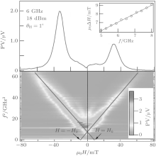
The saturation magnetization and the effective magnetic field can also be determined by this method.[187] It is known that the dynamic properties of the microstrip and the orientation of h induced by CPW can be measured through the photovoltage (PV) effect.[178] The PV signal, which appears as a resonant signal at FMR, is a manifestation of SRE.[185, 188] The resonance positions, indicated by the two solid lines shown in Fig. 7, are determined from Eq. (26). From the slopes and intercepts of these two lines, Ms = 1.07 T, Ha = 75 Oe, and γ = 2.85 MHz/Oe are determined, and the natural resonance frequency fr (FMR frequency at H = 0) of the permalloy (Ni80Fe20, Py) microstrip is estimated as 2.6 GHz. In addition, through a further analysis of the lineshape of the PV signal, the Gilbert damping parameter of the microstrip aG = 0.027 and the h vector configuration induced by the CPW have also been determined (not shown here).[189] Ratios of the amplitudes of the h components along the x, y, and z directions are | hx| /| hy| = 0.062 and | hz| /| hy| = 0.016; these indicate that h inside the microstrip is almost linearly polarized along the y direction.
 | Fig. 7. (a) The FMR of Py represents by the PV signal. Insert: the frequency dependence of the line width of the PV signal. (b) 2D mapping of the PV signal as a function of microwave frequency and applied static magnetic field at θ = 1° . Solid lines indicate the position of FMR.[187] |
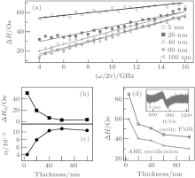
Moreover, the nature of the FMR linewidth Δ H can be analyzed in detail.[180] At low power, linewidth Δ H presents a linear dependence on frequency as Δ H = Δ H0 + α Gω /γ , where Δ H0 is the extrinsic contribution to the FMR linewidth.[190– 192] The frequency dependent linewidths of five samples with different thicknesses are shown in Fig. 8(a). The Δ H0 is found to decrease with the thickness, as shown in Fig. 8(b), which is consistent with the previous reports.[193] The Δ H0 is empirically related to the “ magnetic roughness, ” which is caused by the surface quality in the ultra thin films.[194] Therefore, the extrinsic contribution to the linewidth would be roughly treated as a linear frequency dependent case, wherein the interception gives birth to the “ zero-frequency linewidth” and the slope results in an additional effective Gilbert damping term. Based on this picture, it is reasonable to predict that the effective α G of the Co90Zr10 film should decrease with the film thickness as the surface gets smoother. However, the data in Fig. 8(c) show an inverse trend, which means there are other mechanisms affecting α G while the film is getting thick rather than the two-magnon scattering mechanism.[195]
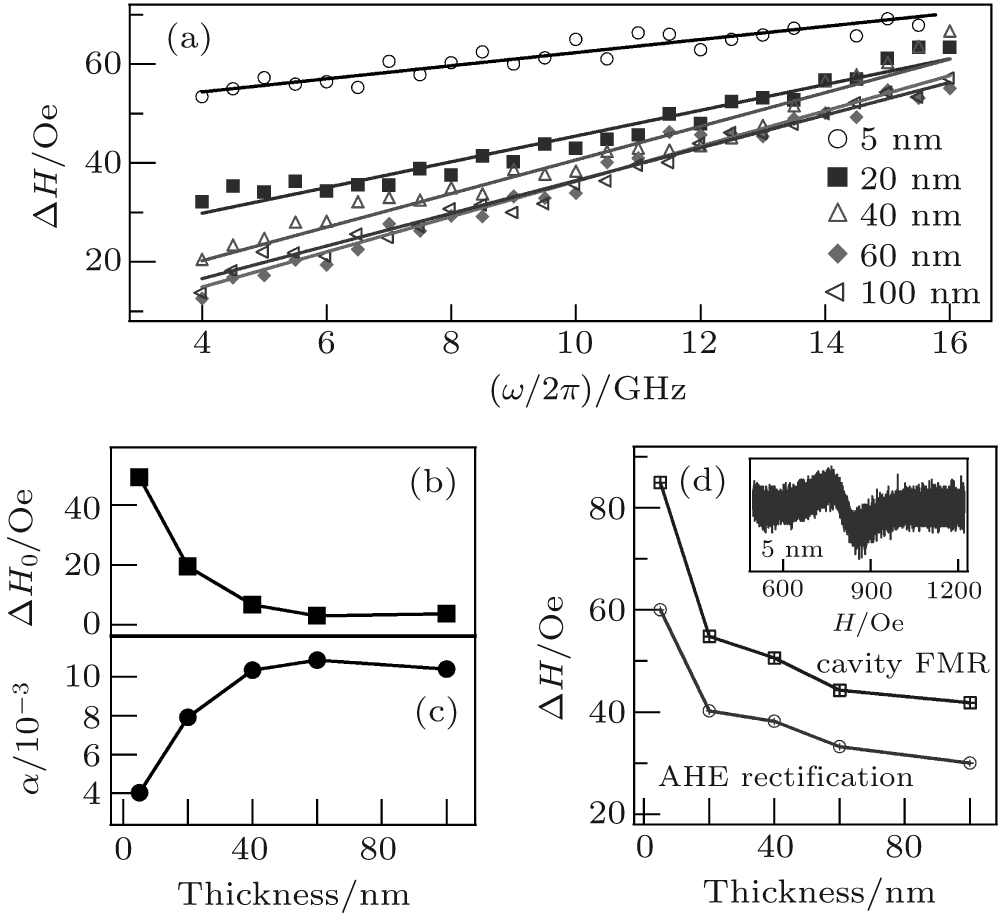 | Fig. 8. (a) Frequency dependent FMR linewidth Δ H for the Co90Zr10 thin films with different thicknesses. (b), (c) The thickness dependence of zero-frequency linewidth Δ H0 and the Gilbert damping α G. (d) Comparision of the linewidth Δ H measured with the cavity FMR and the AHE rectification. The inset in panel (d) shows the cavity FMR spectrum of the sample with thickness 5 nm.[180] |
The values of Δ H obtained by the AHE rectification and by the cavity FMR were plotted in Fig. 8(d). The larger the sample area that contributes to the signal, the more the inhomogeneities would be involved in extrinsic contribution to the linewidth. Two methods reveal a similar thickness dependence, which indicates the validity of the AHE rectification in studying the magnetic damping. On the other hand, the values of Δ H measured with the AHE rectification are smaller than those measured in the cavity FMR. The discrepancy results from the difference of the origin of the measurement signal. In the cavity FMR, the signal comes from the entire thin film sample with an area of a few square millimeters; however, the AHE rectified electric signal comes from a much smaller area (0.01 mm2) defined by the Hall bar structure. Moreover, because the signal of the cavity FMR is directly proportional to the sample volume, the FMR amplitude of the 5 nm sample (100 μ m in width and 3 mm in length) almost meets the sensitivity limit of the equipment, as shown in the inset of Fig. 8(d). In contrast, the AHE rectified voltage is independent of the sample volume and is related to the width of the strip. With fixed current amplitude, the reduction in width would enhance the current density and result in a geometry independent voltage. Therefore, the AHE rectification is more suitable for studying the dynamic properties of local magnet moment.
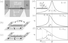
At high power of microwave, a nonlinear dynamic of magnetization, such as nonlinear damping[196] and foldover resonance lineshape, [197, 198] can be observed based on determining the precession cone angle of magnetization.[199] Figure 9(a) shows a top view micrograph of the device, viz., a Py microstrip, 300 μ m long, 100 nm thick, and 5 μ m wide, deposited on a SiO2(2 μ m)/Si substrate via standard electron beam lithography and thermal evaporation. A shorted CPW Cu(200 nm)/Cr(20 nm) was deposited on top of the sample, separated from it by a 200 nm SiO2 isolating layer. In this geometry, the Py microstrip is located directly below the shorted ground (G) and signal (S) strips. The amplitude of the microwave magnetic field h generated by such a CPW is thus able to reach 70 Oe, and its orientation lies in-plane, perpendicular to the Py microstrip. A static magnetic field H was applied perpendicular to the device plane and saturated the Py microstrip. Two different measurement techniques were used: in the first, the sample was irradiated by continuous microwaves as shown in Fig. 9(b); in the second, the microwave intensity was 100% modulated by an 8.33 kHz square wave at low power, as shown in Fig. 9(c). Solving the LLG equation yields the following expression of the cone angle near the position of FMR[197]
where Hr is the resonance magnetic field, Ms the saturation magnetization of the Py microstrip (μ 0Ms∼ 1 T), and Δ H0 the linewidth of the FMR. In the limit h → 0, usually adopted to solve the LLG equation, the FMR peak is centered at H = Hr, as shown in Fig. 9(d). However, as h increases, there are two notable effects. One is the shift in the resonance peak location to low field; the other is the emergence of a foldover lineshape when h exceeds a critical value hth, as illustrated in Figs. 9(e) and 9(f). Meanwhile, the nonlinear damping

is found at large cone angle precession of magnetization.[196]
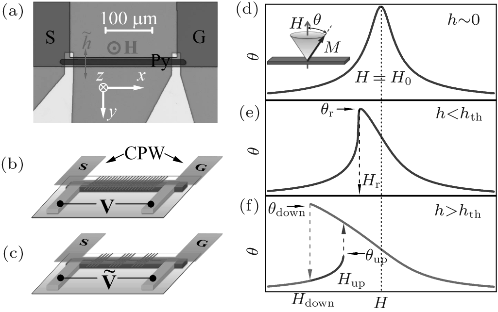 | Fig. 9. (a) Top view micrograph of device, wherein the key component is the Py microstrip embedded under a shorted CPW. Two methods are used to drive spin precession in the Py microstrip, (b) one is by continuous wave, (c) the other is by modulated waves excitation. (d), (e), (f) Theoretical FMR curves for different microwave magnetic field levels.[199] |
Over the past twenty years, the HFMM with high permeability has gained momentum due to the requirements of applications and the systematic studies of several groups (including our group). In this paper, we have briefly reviewed our understanding of the theory, materials, and the related measurement approaches. However, some important questions are still open from the viewpoints of theory and applications, such as 1) What is the best symmetry of anisotropy for the HFMM? 2) How to improve the high frequency properties with an external electrical field? 3) How to extend the resonance frequency of the HFMM (with 100 permeability) over 7 GHz? 4) How to obtain a rotational high permeability of the HFMM? 5) How to determine the permeability and the permittivity of the HFMM at the same time? 6) How to measure the space cone of the magnetization precession of the HFMM?
The authors would like to thank our group members Chai Guo-Zhi, Guo Dang-Wei, and Gao Mei-Zhen for their contributions. We would also like to thank the groups of Li Fa-Shen, Hu Can-Ming, Lu Huai-Xian, and Cheng Zhao-Hua for their collaboration.
| 1 |
|
| 2 |
|
| 3 |
|
| 4 |
|
| 5 |
|
| 6 |
|
| 7 |
|
| 8 |
|
| 9 |
|
| 10 |
|
| 11 |
|
| 12 |
|
| 13 |
|
| 14 |
|
| 15 |
|
| 16 |
|
| 17 |
|
| 18 |
|
| 19 |
|
| 20 |
|
| 21 |
|
| 22 |
|
| 23 |
|
| 24 |
|
| 25 |
|
| 26 |
|
| 27 |
|
| 28 |
|
| 29 |
|
| 30 |
|
| 31 |
|
| 32 |
|
| 33 |
|
| 34 |
|
| 35 |
|
| 36 |
|
| 37 |
|
| 38 |
|
| 39 |
|
| 40 |
|
| 41 |
|
| 42 |
|
| 43 |
|
| 44 |
|
| 45 |
|
| 46 |
|
| 47 |
|
| 48 |
|
| 49 |
|
| 50 |
|
| 51 |
|
| 52 |
|
| 53 |
|
| 54 |
|
| 55 |
|
| 56 |
|
| 57 |
|
| 58 |
|
| 59 |
|
| 60 |
|
| 61 |
|
| 62 |
|
| 63 |
|
| 64 |
|
| 65 |
|
| 66 |
|
| 67 |
|
| 68 |
|
| 69 |
|
| 70 |
|
| 71 |
|
| 72 |
|
| 73 |
|
| 74 |
|
| 75 |
|
| 76 |
|
| 77 |
|
| 78 |
|
| 79 |
|
| 80 |
|
| 81 |
|
| 82 |
|
| 83 |
|
| 84 |
|
| 85 |
|
| 86 |
|
| 87 |
|
| 88 |
|
| 89 |
|
| 90 |
|
| 91 |
|
| 92 |
|
| 93 |
|
| 94 |
|
| 95 |
|
| 96 |
|
| 97 |
|
| 98 |
|
| 99 |
|
| 100 |
|
| 101 |
|
| 102 |
|
| 103 |
|
| 104 |
|
| 105 |
|
| 106 |
|
| 107 |
|
| 108 |
|
| 109 |
|
| 110 |
|
| 111 |
|
| 112 |
|
| 113 |
|
| 114 |
|
| 115 |
|
| 116 |
|
| 117 |
|
| 118 |
|
| 119 |
|
| 120 |
|
| 121 |
|
| 122 |
|
| 123 |
|
| 124 |
|
| 125 |
|
| 126 |
|
| 127 |
|
| 128 |
|
| 129 |
|
| 130 |
|
| 131 |
|
| 132 |
|
| 133 |
|
| 134 |
|
| 135 |
|
| 136 |
|
| 137 |
|
| 138 |
|
| 139 |
|
| 140 |
|
| 141 |
|
| 142 |
|
| 143 |
|
| 144 |
|
| 145 |
|
| 146 |
|
| 147 |
|
| 148 |
|
| 149 |
|
| 150 |
|
| 151 |
|
| 152 |
|
| 153 |
|
| 154 |
|
| 155 |
|
| 156 |
|
| 157 |
|
| 158 |
|
| 159 |
|
| 160 |
|
| 161 |
|
| 162 |
|
| 163 |
|
| 164 |
|
| 165 |
|
| 166 |
|
| 167 |
|
| 168 |
|
| 169 |
|
| 170 |
|
| 171 |
|
| 172 |
|
| 173 |
|
| 174 |
|
| 175 |
|
| 176 |
|
| 177 |
|
| 178 |
|
| 179 |
|
| 180 |
|
| 181 |
|
| 182 |
|
| 183 |
|
| 184 |
|
| 185 |
|
| 186 |
|
| 187 |
|
| 188 |
|
| 189 |
|
| 190 |
|
| 191 |
|
| 192 |
|
| 193 |
|
| 194 |
|
| 195 |
|
| 196 |
|
| 197 |
|
| 198 |
|
| 199 |
|