

Magnetic and mechanical properties of Ni–Mn–Ga/Fe–Ga ferromagnetic shape memory composite*
[Tan Chang-Longa)†  , Zhang Kun
a) , Tian Xiao-Huaa) , Cai Weib) ]
, Zhang Kun|
|


†Corresponding author. E-mail: changlongtan@hrbust.edu.cn
*Projects supported by the National Natural Science Foundation of China (Grant Nos. 51271065 and 51301054), the Program for New Century Excellent Talents in Heilongjiang Provincial Education Department, China (Grant No. 1253-NCET-009), the Youth Academic Backbone in Heilongjiang Provincial Education Department, China (Grant No. 1251G022), the Projects of Heilongjiang, China, and China Postdoctoral Science Foundation.
A ferromagnetic shape memory composite of Ni–Mn–Ga and Fe–Ga was fabricated by using spark plasma sintering method. The magnetic and mechanical properties of the composite were investigated. Compared to the Ni–Mn–Ga alloy, the threshold field for magnetic-field-induced strain in the composite is clearly reduced owing to the assistance of internal stress generated from Fe–Ga. Meanwhile, the ductility has been significantly improved in the composite. A fracture strain of 26% and a compressive strength of 1600 MPa were achieved.
Ni– Mn– Ga based ferromagnetic shape memory alloys (FSMAs), which exhibit giant magnetic-field-induced strain (MFIS) in the martensitic phase, have attracted considerable attention due to their potential applications in new generation actuation and transduction devices.[1– 5] A large MFIS of up to 10% has been reported in Ni– Mn– Ga.[6– 8] The mechanism of giant MFIS is a reorientation of martensitic twin variants under an applied magnetic field by twin-boundary motion. So far, Ni– Mn– Ga FSMAs still have several characteristic shortcomings that greatly limit their potential applications. First, a larger threshold field (depending on sample shape, exact composition, and processing history) is required to activate twin boundary motion and achieve full actuation.[2, 9, 10] In addition, the high brittleness also significantly hampers application of Ni– Mn– Ga FSMAs.[11– 13] Therefore, it is desirable to decrease the threshold field, and significantly improve the ductility. To reduce the threshold field and achieve greater strain under a smaller magnetic field, previous studies[10, 14, 16] demonstrated the application of acoustic energy to assist a magnetic field in driving twin boundary motion in a Ni2MnGa crystal. Acoustic-assisted magnetic-field-induced actuation of Ni– Mn– Ga single crystals has been shown to reduce the threshold fields by up to 1 kOe. The strain can be increased dramatically depending on the magnetic field strength. However, additional facilities are required, adding complications to the device design and fabrication.
In this study, we report an approach for decreasing the threshold field, which is to combine the Ni– Mn– Ga alloys with a low-magnetic field drive magnetostrictive material Fe– Ga to form composites. Compared to the Ni– Mn– Ga alloy, the threshold field in the composite is clearly reduced due to the assistance of internal stress generated from Fe– Ga. In the meantime, the composite exhibits significantly enhanced ductility.
The Ni– Mn– Ga/Fe– Ga composites were fabricated by using a spark plasma sintering method. A Ni50Mn30Ga20 alloy was prepared with high-purity elements melted in an arc-melting furnace under an argon atmosphere. The arc-melted alloy was mechanically crushed and followed by ball milling to achieve Ni– Mn– Ga powder. The Fe– Ga powder was prepared by the atomization method. Subsequently, the prepared powder of Ni– Mn– Ga was mixed with the powder of Fe– Ga in a volume ratio of 10 vol%. The mixture was sintered by the spark plasma sintering technique, sintering being performed at 1073 K for 8 min in a vacuum of 6 Pa under a pressure of 40 MPa in a graphite die. In order to compare the properties between Ni– Mn– Ga/Fe– Ga composites and Ni– Mn– Ga materials, part of the Ni– Mn– Ga powder mentioned above was sintered with the same parameters to form Ni– Mn– Ga sintered samples. Phase identification and crystal structures were determined by means of x-ray powder diffraction (XRD) using Cu Kα radiation. Microstructures of the specimens were studied in an MX2600FE scanning electron microscopy analysis system. Chemical compositions of the samples were measured by x-ray energy dispersive spectrum (EDS) equipped on scanning electron microscopy. The compositions of the Ni– Mn– Ga sintered sample and the Ni– Mn– Ga/Fe– Ga composite were Ni50.2Mn29.6Ga20.2 and Ni50.2Mn29.6Ga20.2/Fe84Ga16, respectively. The martensitic transformation behavior was measured by means of differential scanning calorimetry (DSC) with a cooling/heating rate of 20 K/min. Compression testing was conducted at ambient temperature on an Instron-1186 machine at a strain rate of 0.05 mm· min− 1 using specimens with a rectangular shape of about 3 × 3 × 5 mm3. The MFIS was measured by standard strain gauge techniques. Samples with a dimension of 4 × 3 × 2 mm3 were cut for the measurement of the MFIS. The magnetic threshold field of MFIS is defined to be an average of the magnetic fields at which MFIS begins and completes.
Figure 1(a) shows the room temperature XRD pattern of Ni– Mn– Ga/Fe– Ga composite. The XRD pattern shows the polycrystalline nature well and clearly reveals two sets of diffraction patterns corresponding to Ni– Mn– Ga and Fe– Ga phases without any impurity patterns. These confirm that there is no chemical reaction which has occurred between Ni– Mn– Ga and Fe– Ga. The typical Martensite peaks of Ni– Mn– Ga can be seen clearly. According to the XRD results, the crystal structures of Ni– Mn– Ga in composite can be indexed by the five-layer orthorhombic Martensite with the lattice parameters a = 0.608 nm, b = 0.572 nm, and c = 0.526 nm. Figure 1(b) shows the microstructure of Ni– Mn– Ga/Fe– Ga composite. It is observed that the Fe– Ga particles are dispersed in the Ni– Mn– Ga matrix and they are of irregular shape and size. Moreover, it can be seen that only a small amount of fine pores is observed in the composite. This indicates that the sintering temperature of 1073 K is sufficient to obtain a high density.
Figure 2 shows the DSC curves of the Ni– Mn– Ga/Fe– Ga composite in comparison with that of the Ni– Mn– Ga sintered specimen during heating and cooling. In the case of the Ni– Mn– Ga/Fe– Ga composite, it is found that exothermic and endothermic peaks appear in the cooling and heating curves clearly, corresponding to the martensitic transformation. This indicates that the Ni– Mn– Ga/Fe– Ga composite maintains the characteristics of the typical one-step thermoelastic martensitic transformation of the Ni– Mn– Ga alloy. The martensitic and austenitic transformation starting and finishing temperatures are determined to be Ms = 56.8 ° C, Mf = 23.1 ° C, As = 29.4 ° C, and Af = 69.6 ° C, respectively. In addition, previous studies[17] showed that for the as-sintered Ni– Mn– Ga-based FSMA samples, the martensitic transformation does not occur after sintering, and recovers only after annealing. This phenomenon is attributed to the fact that the stress-induced lattice distortion has led to the inhibition of the martensitic transformation. However, in this study, the martensitic transformation could be observed in an as-sintered state. The reason for these different martensitic transformation behaviors can be deeply understood from the view of microstructure. Previous studies[17] showed that the as-sintered Ni– Mn– Ga alloys exhibited the broadened XRD peaks. Such broadening arises from the simultaneous variation of lattice strain and grain size, which is due to the grinding-induced stress. Compared to previous results, the narrower XRD peaks in our studied sintered Ni– Mn– Ga/Fe– Ga specimens show that lower lattice strain has been produced in the SPS process. This indicates that the appropriate SPS process can eliminate the stress effect in powder thoroughly, which benefits the practical application of this material.
 | Fig. 1. (a) XRD pattern and (b) microstructure of the Ni– Mn– Ga/Fe– Ga composite. |
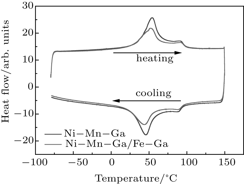 | Fig. 2. DSC curves of the Ni– Mn– Ga/Fe– Ga composite and Ni– Mn– Ga sintered specimen. |
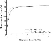
Figure 3 illustrates the magnetization curves of the Ni– Mn– Ga/Fe– Ga composite and the Ni– Mn– Ga sintered specimen measured at room temperature. It can be seen that the magnetization curve of the Ni– Mn– Ga/Fe– Ga composite is quickly increased until saturation for an applied magnetic field close to 7 kOe. The saturation magnetization of the Ni– Mn– Ga/Fe– Ga composite is 63 emu/g, which is higher than that of the Ni– Mn– Ga sintered specimen. The high saturation magnetization is favorable to the MFIS. Moreover, according to the XRD results, the crystal structure of Ni– Mn– Ga/Fe– Ga at room temperature is five-layer orthorhombic Martensite. Therefore, the magnetization curve indicates that the martensitic phase of sintered Ni– Mn– Ga/Fe– Ga exhibits the typical ferromagnetic behavior, which is the basic condition for observation of MFIS in ferromagnetic shape memory alloys.
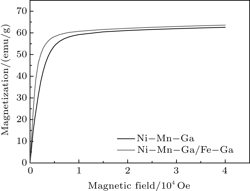 | Fig. 3. Magnetization curves of Ni– Mn– Ga/Fe– Ga composite and Ni– Mn– Ga sintered specimen. |
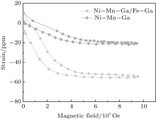
Figure 4 shows the results of the MFIS measurements in the Ni– Mn– Ga/Fe– Ga composite and Ni– Mn– Ga sintered specimen. In the case of Ni– Mn– Ga/Fe– Ga composite, the MFIS reaches a strain of 70 ppm at 0.3 T approximately. As the field returns to zero, the strain is not reversed because there is no restoring force. Since twin boundary motion is irreversible, a bias stress is required to reset FSMA samples as the magnetic field approaches zero. It is worth noting that compared to the Ni– Mn– Ga alloy, the threshold field for magnetic-field-induced strain in the Ni– Mn– Ga/Fe– Ga composite is clearly reduced, which is as much as a 50% reduction. The physical mechanism for the decrease of the threshold field is discussed in the following. The giant MFIS of Ni– Mn– Ga is based on the rearrangement of martensitic twin variants by the twin boundary motion under an applied magnetic field. The high magnetocrystalline anisotropy of the ferromagnetic twinned Martensite in this material cause the twin structure to reorient due to the applied external field, simultaneously changing the shape of the material, since the twinning stress (σ tw) is low enough to allow the twin boundary motion. In Ni– Mn– Ga alloys, the preferred direction of magnetization changes in the neighboring twin, thus the application of a magnetic field results in a difference in the Zeeman energy across the twin boudndary. This energy difference imposes a magnetic stress (σ mag) on the twin boundary. Increasing the magnetic field increases further the σ mag. When the σ mag is larger than σ tw, the twin boundary moves and the whole twin structure has changed. Actually, twin-boundary motion in Ni– Mn– Ga-based FSMAs may be induced by the application of either a magnetic field or a mechanical stress. Thus, applying mechanical stress to assist a magnetic field in driving twin boundary motion in Ni– Mn– Ga-based FSMAs may reduce the threshold field. In this study, the magnetostrictive material Fe– Ga in the composite just provides an internal stress to the FSMA sample so that twin boundary motion becomes easier. Therefore, the threshold field is decreased in the Ni– Mn– Ga/Fe– Ga composite.
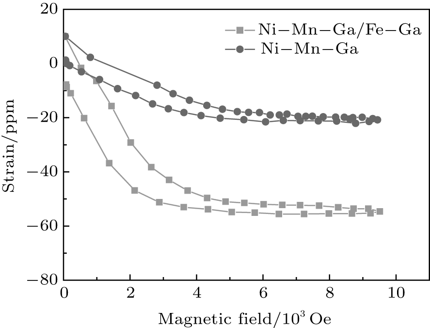 | Fig. 4. MFIS of Ni– Mn– Ga/Fe– Ga composite and Ni– Mn– Ga sintered specimen. |
Moreover, it is obviously found that the obtained MFIS is low and comparable to that of the polycrystalline bulk alloy and ribbon.[18] On the other hand, it is noted that the dense sintered specimen is composed of the grains perfectly surrounded by neighboring grains. Thus, the low MFIS may be due to the incompatibilities across the grain boundaries and limited Martensite reorientation caused by the geometric constraints from surrounding grains during deformation. Recently, it has been reported that introducing pores in polycrystalline Ni– Mn– Ga drastically increases its MFIS by reducing the effect of constraints imposed by grain boundaries and thus enabling twin boundary motion.[19, 20] Therefore, we infer that introducing appropriate pores in the sintered Ni– Mn– Ga/Fe– Ga composite would make this material exhibit both large MFIS and low threshold field.
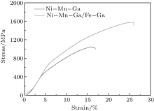
In order to investigate the ductility of the Ni– Mn– Ga/Fe– Ga composite and compare it with that of Ni– Mn– Ga sintered specimen, compression tests were carried out at room temperature. Both specimens were compressed to fracture. Figure 5 shows the compressive stress-strain curves at room temperature obtained from the Ni– Mn– Ga/Fe– Ga composite and Ni– Mn– Ga sintered specimen. It can be seen that the Ni– Mn– Ga sintered specimen is subject to 17% fracture strain. On the other hand, in the Ni– Mn– Ga/Fe– Ga composite, the fracture occurred at a strain of about 26%. Moreover, the compressive strength of 1600 MPa is obtained for the Ni– Mn– Ga/Fe– Ga composite, which is also significantly higher than that of the Ni– Mn– Ga sintered specimen. Therefore, both the compressive strength and fracture strain of the sintered specimen are far higher than those of the sintered and arc-melted specimen of Ni– Mn– Ga. This clearly demonstrates that the ductility of the Ni– Mn– Ga/Fe– Ga composite is significantly enhanced by powder metallurgy using the SPS technique. It is well known that grain refining is considered as the most effective method to improve compressive strength and fracture strain. The enhancement of the ductility for the sintered specimen compared to Ni– Mn– Ga melted alloy may be attributed to the strengthening of grain boundaries and reduction of the grain size, which has been reported in Cu-Al-Ni alloys.[21] However, the significantly enhanced ductility of the Ni– Mn– Ga/Fe– Ga composite compared to the Ni– Mn– Ga sintered sample cannot be explained by the effect of grain size because these two samples exhibit approximately the same average grain size of 50 μ m. On the other hand, it is known that Fe– Ga particle exhibits high ductility. Therefore, it can be inferred that the reason for the increasing ductility of the Ni– Mn– Ga/Fe– Ga compared to the Ni– Mn– Ga sintered sample is mainly attributed to the high ductility of the Fe– Ga particle.
 | Fig. 5. Stress-strain curves of Ni– Mn– Ga/Fe– Ga composite and Ni– Mn– Ga sintered specimen at room temperature. |
In summary, we have fabricated Ni– Mn– Ga/Fe– Ga ferromagnetic shape memory composite by using the spark plasma sintering method. The magnetic and mechanical properties of the composite have been investigated. It is found that compared to the Ni– Mn– Ga alloy, the threshold field for magnetic-field-induced strain in the composite is clearly reduced. This is attributed to the assistance of internal stress generated from Fe– Ga in driving twin boundary motion. Meanwhile, a fracture strain of 26% and a compressive strength of 1600 MPa were achieved in the composites, which are far higher than those of Ni– Mn– Ga alloy.
| 1 |
|
| 2 |
|
| 3 |
|
| 4 |
|
| 5 |
|
| 6 |
|
| 7 |
|
| 8 |
|
| 9 |
|
| 10 |
|
| 11 |
|
| 12 |
|
| 13 |
|
| 14 |
|
| 15 |
|
| 16 |
|
| 17 |
|
| 18 |
|
| 19 |
|
| 20 |
|
| 21 |
|