


Anisotropic transport properties of charge-ordered La5/8− yPr yCa3/8MnO3 ( y = 0.43) film*
[Liu Yuan-Bo, Wang Shuan-Hu, Sun Ji-Rong† , Shen Bao-Gen]
, Shen Bao-Gen]
|
|


†Corresponding author. E-mail: jrsun@iphy.ac.cn
*Project supported by the Knowledge Innovation Project of the Chinese Academy of Sciences and the National Basic Research Program of China.
The anisotropic resistances along [001] and [1-10] axes are investigated for an La5/8− yPr yCa3/8MnO3 ( y = 0.43) (LPCMO) film grown on (110)-oriented LaAlO3 substrate. It is found that the charge order (CO) transition is much stronger and the resistance is larger along the [001] direction than that along the [1-10] direction. Special attention has been paid to the different effects of a magnetic field on the resistances of the two axes. The resistance is more susceptible to the magnetic field along the [001] direction compared with that along the [1-10] direction. Our results demonstrate that the anisotropic transport properties can be ascribed to the intrinsic anisotropic strain field in the film, which changes the shape of metallic domains for the phase separation manganite film. We also provide a feasible method to rule out the Joule heat effect from the electric current effect. This could be useful for future construction and application of materials and devices.
The manganites have been extensively studied in the last decades due to the strong coupling among spin, charge, and orbital degrees of freedom in them.[1– 8] Generally, the striking aspects of manganites include the charge ordering, orbital ordering (OO), phase separation (PS), and metal– insulator transition (MIT), which are induced by external impacts, such as magnetic field, electric field, laser radiation, and strain.[9– 13] Especially, in the case of a thin film, which is different from the bulk material, the intrinsic strain resulting from the substrate provides an effective approach to manipulate the physical properties of the manganite film.[14, 15] For example, through tuning the orbital occupancy via lattice strains, the La1− xSrxMnO3 films can be driven from the ferromagnetic (FM) to antiferromagnetic (AFM) state.[16]
The magnetic and resistive properties related to the strain have been paid attention to. Manganite films with different strains show distinct magnetotransport behaviors. For instance, the La1− xCaxMnO3 film grown on SrTiO3 (STO) substrate suffers from a tensile strain, preferring the dx2− y2 orbital and the A-type antiferromagnetic spin ordering. Meanwhile, the in-plane Mn– O bond length is stretched under the tensile strain so that the overlapping between Mn 3d and O 2p orbitals is reduced, which in turn suppresses the metal– insulator transition temperature Tp. As a comparison, the film on LaAlO3 (LAO) substrate suffers from a compressive strain, preferring the d3z2− r2 orbital and the C-type AFM ordering.[17, 18] On the other hand, the anisotropic magnetic and transport properties have also been investigated. In Ref. [19], a large anisotropy of ∼ 1000 in the colossal magnetoresistance (CMR) effect was observed in Sm0.5Ca0.5MnO3 films grown on (110) STO substrates. Moreover, a much greater resistivity drop along the [1-10] direction was found compared to that along the [001] direction under a magnetic field, implying a significantly stronger spin– orbital coupling deriving from the intrinsic asymmetric strain along the [1-10] direction than that along the [001] direction.[19] Shen et al.[20] also found anisotropic magnetic and transport properties driven by anisotropic long-range elastic coupling between film and substrate in the LPCMO/NdGaO3 film. Preferential orientation of electronic phase domains formed along one axis more easily. Besides, the anisotropic resistivity triggered by anisotropic strain has also been reported by Wu et al.[21, 22] They claimed that the strain could stabilize a shear-mode deformation of the MnO6 octahedra in the La0.67Ca0.33MnO3 films, which may organize the competing phases into orientation-preferred phase separation patterns, thus leading to anisotropic resistivities.
So far, much work has been done to elucidate the effect of strain on transport and magnetic properties.[23] However, investigations on the anisotropic transport properties of the films are relatively limited, especially for those grown on the (110)-oriented LAO substrate. Meanwhile, no consensus in the anisotropic mechanism has been reached yet. Based on this consideration, in this work, we study the anisotropic transport behaviors in the (110)-oriented LPCMO/LAO film. Furthermore, we investigate the effects of a magnetic field on the resistances along [001] and [1-10] axes and find that the magnetic field can regulate the resistance along the [001] direction more easily compared with that along the [1-10] direction. In addition, the phase evolution is studied systematically. Our findings suggest that the anisotropy in the transport properties can be attributed to the intrinsic asymmetric strain field in the film, which strongly influences the shape of metallic domains in the manganite film.
A La5/8− yPryCa3/8MnO3 (y = 0.43) film was grown on the (110)-oriented LAO substrate by pulsed laser deposition using a KrF excimer laser (λ = 248 nm). During deposition, the substrate temperature and oxygen pressure were kept at 700 ° C and 45 Pa, respectively. After deposition, the sample was slowly cooled down to room temperature under an oxygen pressure of 103 Pa. The film thickness is 300 nm. To obtain the anisotropic resistances, namely, the resistances along the in-plane [001] and [1-10] directions, the LPCMO film was patterned by the conventional photolithography and chemical etching technique (shown in the inset of Fig.2). The transport measurements were performed in a vibrating sample magnetometer (VSM) made by Quantum Design. Since the resistance of the sample is very high at low temperatures, we had to measure it using a Keithley 6517B electrometer with the two-probe method, which can extend the measurement of resistance to 1010 Ω or higher. Moreover, as we checked, the contact resistance in our sample is minor and can be neglected. However, to study the electric current effect of the film, a standard four-probe configuration was also adopted using a Keithley 2400 SourceMeter and a 2182 Nanovoltmeter.
Figure 1(a) shows the XRD linear scan around LAO (110) reflection for the LPCMO film. A clear LPCMO (110) peak is observed and its full width at half maximum (FWHM) is narrow, implying that the film is uniform with high crystalline quality. To investigate the in-plane strain behavior, we measured reciprocal space maps (RSM) around the LAO (130) and (222) Bragg reflections in the LPCMO film, see Figs. 1(b) and 1(c). The doped LPCMO has a similar structure to LCMO, which can be indexed in Pbnm symmetry with aOr = 0.5472 nm, bOr = 0.5457 nm, and cOr = 0.7711 nm. It is often represented by a pseudo-cubic lattice with a lattice parameter of 0.3856 nm. For the pseudocubic LAO substrate, the lattice constants are the same 0.3788 nm. As a result, epitaxial deposition of LPCMO film on LAO substrate can give rise to an in-plane compressive strain of − 1.76% when the strain is not relaxed. From the results in Fig. 1, d[001] is 0.383 nm (0.3788 nm for LAO substrate, 0.3856 nm for bulk LPCMO), whereas d[1− 10] is 0.271 nm (0.2678 nm for LAO, 0.2729 nm for bulk LPCMO), indicating a partial relaxation of the strain along [001] and [1-10] axes appears. What is more, the anisotropic strain can be deduced fromn = (dbulk − dfilm)/dbulk. The compressive strains are obtained, which are − 0.58% along the [001] axis and − 0.77% along the [1-10] axis. Therefore, the results suggest that the anisotropic compressive strain exists in our LPCMO film.
 | Fig. 1. (a) XRD linear scan around the (110) reflection for the LPCMO film. RSMs of asymmetric reflections (b) (130) and (c) (222) for the film. |
Figure 2 shows the resistances along the in-plane [001] and [1-10] directions of the sample as a function of temperature. Remarkably, the charge order transitions are observed at about 245 K along the two directions. It clearly demonstrates that the charge order transition along the [001] direction is stronger than that along the [1-10] direction, and the resistance is larger along the [001] direction below the charge order transition temperatureTco. The inset of Fig. 2 gives the schematic of the patterned sample.
To explore the different effects of the magnetic field on the resistances along the two directions, we measured R– T curves under different magnetic fields (2 T, 3 T, 4 T, 5 T, 6 T) along in-plane [001] and [1-10] directions, as shown in Figs.3(a)– 3(e). When the magnetic field increases to 3 T gradually (shown in Figs. 3(a) and 3(b)), the difference of resistances between the two directions decreases in the temperature range from 20 K to 70 K. Note that there appears a valley at 110 K during the process of temperature going up and the width of the hysteresis between warming and cooling cycles increases along the [001] direction. Furthermore, when the magnetic field is kept at 4 T, the insulator– metal transition is observed at about 70 K along [001] and [1-10] directions during cooling. And the resistance along the [001] direction becomes smaller than that along the [1-10] direction below the crossing temperature of 125 K during the cooling process and below 150 K during the warming process. Based on those reported previously, the depressed resistance could be attributed to the appearance of a ferromagnetic-metal (FM) state. For our sample, especially below the crossing temperature, the proportion of emerging FM state is much larger along the [001] direction. When the magnetic field further increases, the insulator– metal transition points shift towards the higher temperature and the transition points along [001] have a higher value, also further implying much more FM phase emerging along the [001] direction. This phenomenon suggests that the resistance is more susceptible to the magnetic field along the [001] direction belowTco, compared with that along the [1-10] direction.
We have already known that the magnetic field makes the resistances decline more seriously along the [001] direction. It is significant to clarify whether this effect is related to the direction of the magnetic field or not. Thus, we measured the resistances of the film with the magnetic field along [001] and [1-10] axes respectively, the results are shown in Figs.4(a) and 4(b). As seen in Fig. 4, the sample is cooled at zero field to 75 K, then is warmed at 3 T. Although the magnetic field along the [1-10] direction makes the resistances of [001] and [1-10] axes be smaller than that when the magnetic field is along the [001] direction, the relationship of resistances between the two axes keeps unchanged. The resistance of the [001] axis is still
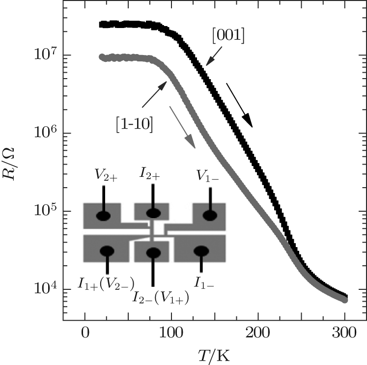 | Fig. 2. Resistances as a function of temperature for LPCMO film grown on (110) LAO substrate, with measuring current along [001] and [1-10] axes, respectively. The inset shows the sample structure and the electrode configuration. |
 | Fig. 3. Temperature dependence of the resistances for LPCMO film along both [001] and [1-10] directions (I| | [001] and I| | [1-10]) under various magnetic fields: (a) 2 T, (b) 3 T, (c) 4 T, (d) 5 T, (e) 6 T. The measuring voltage is set to 5 V. |
lower than that along the [1-10] axis below the cross point in low temperature. The results above indicate that the direction change of the magnetic field exerts an influence on the resistances of [001] and [1-10] axes, but the relative relationship of resistances along the two axes remains unchanged, implying that the direction of the magnetic field is not a critical factor in determining the anisotropic resistance changes.
 | Fig. 4. Resistances versus temperature for LPCMO/LAO film, measured with (a) H = 3 T and I, H| | [001], (b) H = 3 T and I, H| | [1-10]. |
The phase evolution is important to investigate the anisotropic transport properties in the film. We first cooled the sample to 20 K in zero field, then measured the resistances under different magnetic fields. From Fig. 5(a), with the change of the magnetic field from 0 T to 4 T, there is a steep drop of resistance between the frozen temperature (FT) and 110 K, subsequently the decline speed is slow as the temperature increases continuously. In other words, the curve shows a valley at about 110 K. While the magnetic field reaches 4 T and 5 T, the resistances decrease 3– 4 orders of magnitude in the low temperature. This phenomenon suggests that the magnetic field can convert the insulation state to the metallic state easily in low temperature, namely, the FM phase is dominant in low temperature, but soon afterwards the insulation phase reappears and prevails gradually under the magnetic field. It is noteworthy that the frozen temperature gradually reduces on increasing the magnetic field. Specifically, even under a magnetic field of 5 T, there still exists CO insulation state which keeps larger resistance. It is easy to understand since the PS is frozen partially due to the immovable phase boundaries in the low temperature after the zero-field-cooling (ZFC) process, and a higher magnetic field can destroy the frozen state more easily. The field-cooling (FC-6 T) zero-field-warming (ZFW) result is shown in Fig. 5(b). The sample was cooled to 20 K at 6 T, and then warmed at zero field. The resistance of the sample exhibits a sharp jump (nearly five orders) between 20 K and 44 K. It reflects that the magnetic field induced FM phase, which is unstable, can recover once the magnetic field is removed.
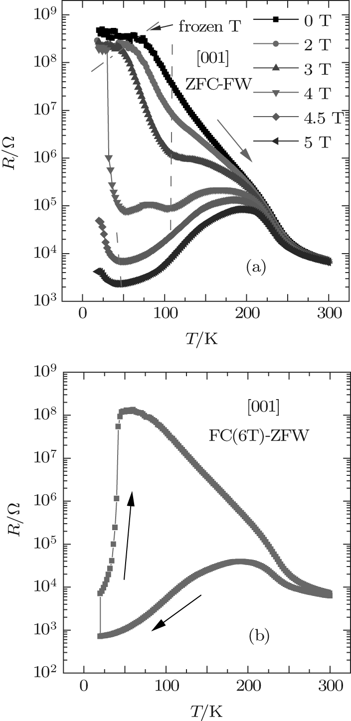 | Fig. 5. (a) The R– T curves measured along [001] direction during ZFC-FW under various magnetic fields as denoted. (b) Resistance– temperature curve measured along [001] direction during ZFW after the film was cooled to 20 K under a magnetic field of 6 T. |
Now, in order to investigate the phase instability under magnetic fields, we measured R– H curves after the film was cooled under zero field from 300 K to various target temperatures with the magnetic field along [001] and [1-10] axes, as shown in Figs.6(a) and 6(b). At 260 K, the curve is reversible. With the decreasing target temperature, the appearance of the CO phase gives rise to hysteretic R– H, typical of some PS manganites. As the temperature is at 20 K, closed loops are not observed with the magnetic fields along [001] and [1-10] axes. Clearly, when the magnetic field increases, the resistances descend, manifesting that the CO phase can be melted into FM phase under the magnetic field; subsequently with the decrease of the magnetic field, the resistances increase, the CO phase can reenter. It is seen that the area of the hysteresis loop is much smaller whenH keeps along the [1-10] axis than that when H is along the [001] axis. Furthermore, it is obvious that as H decreases, the temperatures of restoring CO phase with magnetic field along [1-10] is higher than that while the magnetic field remains along the [001] axis. These experimental results show that the CO phase is more robust along the [1-10] axis, implying that the phase competitions are anisotropic, which is consistent with the conclusion of Fig.3. Namely, the magnetic field can alter the resistance along the [001] direction more easily.
 | Fig. 6. The R − H curves measured after the film was cooled under zero field from 300 K to different target temperatures. The arrows indicate the directions of field cycling: (a) I| | [001], H| | [001]; (b) I| | [1− 10], H| | [001]. |
Generally, LPCMO is typical phase-separated, manganite-FM phase and CO insulating phase coexist below Tco.[24] In addition, the film grown on (110)-oriented LAO substrate exhibits clear anisotropic strain, resulting in obvious transport anisotropy along [001] and [1-10] directions.[25] For our film, the compressive anisotropic strains are obtained, − 0.58% along the [001] axis and − 0.77% along the [1-10] axis. The strain field along the [001] axis is smaller than that along the [1-10] axis. According to the previous model, the formation of the phase separation depends sensitively on the long-range elastic strain. Applying an anisotropic strain field from the substrate can change the formation and the orientation of metallic domains in the insulation domain background.[20] From our experiment result in Fig. 2, the measured resistance along the [1-10] axis is substantially lower. It is because the larger strain field brings about the elongated metallic domains along the [1-10] axis, the electric current travels across the metallic domains with least resistance more easily, leading to the smaller resistance along the [1-10] axis. However, in the following anisotropic magnetotransport investigations under different magnetic fields shown in Fig.3, we find that the resistance along the [001] axis becomes lower with the increase of the magnetic field. In Ref. [23], it was suggested that an in-plane easy axis is along the [001] axis. Furthermore, based on the result of Fig.6, the fraction of FM phase is much more along the [001] direction under the magnetic field. Therefore, we believe that with the increase of the magnetic field to 3 T and even larger, the magnetic field will dominate over the strain field and make the proportion of the FM domains larger along the [001] axis than that along the [1-10] axis, resulting in the smaller resistances along the [001] axis under magnetic fields for our LPCMO/LAO film. As a result, the anisotropic strain field leads to anisotropic resistances along the two axes and different responses ofR[001] and R[1− 10] with respect to the external magnetic fields. On the other hand, because the (110)-orient LAO substrate gives anisotropic compressive strain, the sample exhibits different anisotropic transport properties, in contrast to that of some manganites grown on STO (110) substrate with tensile strain.[19] However, further investigations are needed to reveal a more detailed mechanism underlying the anisotropic transport properties.
We wondered whether or not the electric current can produce different influences on the resistances along the two axes. We measured the temperature dependent resistances with 1 μ A and 8 mA currents respectively, the results are shown in Figs. 7(a) and 7(b). Evidently, the resistance above 190 K declines dramatically. After careful study, we find that the measuring current is lower than 8 mA below 190 K due to the measured voltage outside the limit of a 2400 SourceMeter. Hence, we speculate that this phenomenon correlates with the heating effect. To confirm this, we first thinned the substrate, then deposited a stripe-like Pt onto the backside of the film, next measured the resistances of the sample and Pt simultaneously, as shown in Figs. 7(a) and 7(b). We can obtain the temperature-revised resistance of the film through comparing two resistances of Pt, displayed in Fig. 6(c). The results show that the resistance measured with 8 mA coincides with that measured with 1 μ A, indicating that the current has no effect on the resistance. Here we have provided a feasible method to rule out the Joule heat effect from the electric current effect.
 | Fig. 7. Resistances as a function of temperature for the film and Pt when the electric current is along [001] direction. (a) Resistances measured with 1 μ A for the film and Pt, (b) the film was measured with 8 mA while Pt was measured with 1 μ A, (c) temperature-revised resistance for the film. The resistances measured with 1 μ A and 8 mA are also shown in panel (c). |
We have investigated the anisotropic resistances along [001] and [1-10] axes for an LPCMO/LAO film. The results showed that the CO transition is stronger and the resistance is larger along the [001] direction, compared with that along the [1-10] direction. Furthermore, we studied the different effects of a magnetic field on the resistances of the two axes. The magnetic field can influence the resistance along the [001] direction more easily than that along the [1-10] direction. These results demonstrated that the large anisotropy in the transport properties can be ascribed to the intrinsic asymmetric strain in the film, which plays an important role in tuning the shape of FM domains in manganite films. At last, we also provided a feasible tool for ruling out the Joule heat effect from the electric current effect, which could be useful for future study.
| 1 |
|
| 2 |
|
| 3 |
|
| 4 |
|
| 5 |
|
| 6 |
|
| 7 |
|
| 8 |
|
| 9 |
|
| 10 |
|
| 11 |
|
| 12 |
|
| 13 |
|
| 14 |
|
| 15 |
|
| 16 |
|
| 17 |
|
| 18 |
|
| 19 |
|
| 20 |
|
| 21 |
|
| 22 |
|
| 23 |
|
| 24 |
|
| 25 |
|