

Spin transport in a Zigzag normal/ferromagnetic graphene junction
[Shi Hao-Sheng† , Grigoryan Vahram L.]
, Grigoryan Vahram L.]
|
|


†Corresponding author. E-mail: 11210190010@fudan.edu.cn
We study magnetic proximity effect induced low-energy spin transport in the normal/ferromagnetic junction of a semi-infinite zigzag graphene nanoribbon. Due to the absence of a spin flip in a single interface, the spin transfer in this model can be described by the “two-spin channel” model. We identify each spin channel as either a perfect conducting or a non-conducting channel. This feature leads to spin filter in symmetric zigzag graphene nanoribbon and spin precession in antisymmetric zigzag graphene nanoribbon, and helps to directly determine the exchange-splitting intensity directly, even without an external auxiliary bias.
A two-dimensional lattice of graphene is the simplest form of carbon allotrope, such as fullerenes, carbon nanotubes, and graphite in a single layer.[1] These allotropes show strikingly different physical properties, which are principally the result of the dimensionality of their structures. Having the simplest honeycomb lattice, graphene attracted considerable research interest in theoretical study, even before being found experimentally.[2, 3] The primordial research focused on an infinite graphene sheet with a honeycomb lattice which has unique electron states, such as pseudo-spin[1, 2] and electron structure.[4– 6]
An infinite sheet exhibits intriguing tunable-scattering phenomena, [7] principally because the Dirac electron at two valleys forms a time-reversed pair in opposite chirality.[1, 8] Haugen, Yokoyama, and their coauthors studied spin transport in magnetic graphene sheet without a specific edge, which was induced by the magnetic proximity effect.[9– 12] In a normal/ferromagnetic/normal graphene junction, the proximity-induced exchange splitting can be observed by measuring the tunnelling conductance with the aid of an auxiliary barrier built on the top of the ferromagnetic region, or just in plane. In Yokoyama’ s model, [9] conductance in two spin directions has an oscillating behavior with respect to the chemical potential in a ferromagnetic ribbon, which helps to determine proximity splitting.
A finite nanoribbon with simple edges can be shaped as an armchair or as a zigzag.[1, 13] The presence of edge geometry has a strong influence on dispersion and electron transport properties. In pristine zigzag ribbons, the appearance of edge states contributes to a series of intriguing phenomena, such as zero-conductance Fano resonances, [14] valley filtering, valley valve effect, [15] and half-metallic conduction.[16– 19] Furthermore, ribbons with finite impurities always have one perfect conducting channel as long as inter-valley scattering is absent.[20] This feature, along with long mean free path and spin flip length in graphene, [12] facilitates measurement of proximity splitting from an experimental point of view without auxiliary bias in a ferromagnetic ribbon.
We study the spin transport in proximity-induced magnetic graphene junction with a zigzag edge. We show that the spin filter mechanism can be observed directly in an energy range within proximity splitting by measuring spin polarization. Proximity splitting can be directly studied by analyzing the width of the sink in charge conductance of a symmetric zigzag nanoribbon (ZGNR). Besides, an antisymmetric zigzag nanoribbon (AZGNR) displays energy-resolved in-plane spin precession, giving rise to the measurable oscillating spin torque exerted on magnetic nanoribbon. Such a distinct spin-transfer pattern may serve as a new method to distinguish symmetric and antisymmetric zigzag graphene nanoribbons.
This paper is organized as follows. In Section 2, we explain the model of a proximity-induced magnetic graphene junction and the model of spin-dependent transport.[21] In Section 3, we show spin current density and spin transfer torque[21] in ZGNR and AZGNR. We propose a new method to measure proximity splitting and distinguish ZGNR and AZGNR from the perspective of spin transport. In Section 4, we conclude our results.
We consider a normal/ferromagnetic junction composed of a zigzag graphene nanoribbon, which has both ZGNR and AZGNR geometries.[22] Two configurations are distinguished in terms of the symmetry about the central line. The external magnetism is induced by applying a magnetic insulator on top of the right-hand side of this ribbon (Fig. 1). The interface lies along the y axis at x = 0. All of the bonds of the graphene nanoribbon at the two zigzag edges are terminated by hydrogen atoms, and thus do not contribute to the electronic states near the Fermi level. Therefore, this model can be simply described with a continuum Dirac Hamiltonian[23, 24] plus boundary condition,

where the potential profile is U(r) = ± vθ (x), with θ (x) being a step function, and σ = (σ x, σ y) is the vector of Pauli matrices describing popularity of sublattices A and B (Fig. 1) in each unit cell. The basis is 

In Eq. (1), 2v is exchange splitting induced in ferromagnetic ribbon, and ± stands for spin alignment to external magnetism. Without off-diagonal terms in Hamiltonian, two valleys naturally decouple in the low excited energy spectrum and this may lead to a single bound chiral mode, which contributes to one perfect conducting channel (PCC).[20] For a system having translation symmetry in the x direction, the wave function[25] is separated to


where the valley index τ = ± 1 for two valleys at two K points (Kτ = τ 4π /3a), and ε τ = ± vFħ qcsc(qw) is the valley-independent dispersion. Wave number kτ = Kτ + τ qcot(qw) is also valley-independent and χ τ is pseudo-parity.[25] Here, a is the lattice constant and vF is the Fermi velocity. ZGNR and AZGNR can be distinguished by the pseudo-parity that plays a role of chirality. In addition, η τ has a constant value of 1 for ZGNR, except for the case of AZGNR when η τ = − τ .
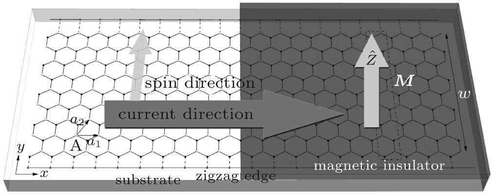 | Fig. 1. Normal/Ferromagnetic junction constructed with infinite N = 8 AZNGR. N is the number of honeycomb units in a primitive cell. The width  |
The band structure of ZGNR and AZGNR is shown above (Fig. 2). The exchange splitting caused by EuO could be very large.[26] Here we choose a relatively small one ∼ 200 × vFħ /e meV. Comparison of dispersion shows that the continuum model coincides well with tight-binding model, especially in a low energy regime. We illustrate parity change in Figs. 2(a) and 2(b), leading to prohibition or allowance of inter-valley scattering in each spin channel of ZNGR or AZGNR.
 | Fig. 2. Schematic illustration of two transport scenario: (a) N = 19-ZGNR, (b) N = 20-AZGNR. The panels from left to right correspond to the band structure for normal ribbon, magnetic ribbon for majority spins, and magnetic ribbon for minority spins. The gray dashed curves result from tight-binding approximation, and the solid red/blue curves are calculated from the Dirac Hamiltonian for continuum approximation. The red and blue denote the parity in bulk states. The green line depicts edge states. |
We study the spin transfer in the construction formed by two semi-infinite graphene nanoribbons. The ribbon on the right-hand side is attached with a magnetic insulator. We assume the chemical potential of left reservoir to be higher than that of right one, so a net charge current is constantly generated through the junction. In the presence of single interface in graphene, spin flipping in vicinity of interface is negligible. We apply “ two conducting channel” model which assumes that coherence of spin-up and spin-down states is preserved at each wave number on Fermi level.[21, 27] The wave number of each band is denoted by transverse part qn and longitudinal part kn, where n is the band index. Due to the inter-valley scattering, we consider both intra-valley and inter-valley back-scatterings. By matching the wave function at the interface, and including evanescent states, we have Ψ L| x= 0 = Ψ R| x= 0,

where Ψ L/R describes the left-hand or right-hand side wave function, 


Furthermore, we study the spin current density and spin transfer torque in the ZGNR and AZGNR junction. The spin current density tensor is

By neglecting spin flip near the interface, spin transport can be approached by a spin-dependent transport which considers that the coherence of spin-up and spin-down current is maintained at each wave number on the Fermi level.[21, 27] Spin transfer torque is usually generated in the bulk due to nonconservation of spin flux in an arbitrary region. More accurately, it emerges from net flux of spin current into and out of a closed surface of a volume, nc = − f∇ · Q. Spin transfer torque can also lead to discontinuity in the spin current near the interface. The two mechanisms to achieve this are the spin filter and spin rotation, reflecting transverse spin back. In addition, the precession-induced averaging effect that wipes out the out-going transverse component of the spin current also creates spin transfer torque. Particularly, for a 1D system, when purely parallel or antiparallel magnetic layers are considered, spin currents pass through the interface freely. Thus, only the transverse spin current generally contributes to the spin transfer torque in the ferromagnet, owing to the nonconservation of spin in this region. Before illustrating several typical patterns in ZNGR and AZNGR, we study spin current density and spin transfer torque analytically.
For spin transport in a 1D graphene junction, we mainly focus on spin current density Qx related to longitudinal component of current density, which is a spatial x-component of tensor Q (Eq. 9). In a linear response regime, we identify incident spin current density per unit chemical potential as

For a net charge current with small energy range, this result is accurate since the average effect is negligible. The rest components of either transverse current density Qy or longitudinal ones Qx for reflected and transmitted flux can easily be derived by such a straightforward technique. These fluxes in both directions cause spin torque.
In this section, we show the typical spin transfer pattern in both ZNGR and AZNGR. To analyze the spin transfer torque in this junction, the spin of incident current is aligned with the y direction (Fig. 1).
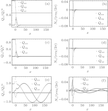
For low-energy spin transport, we concentrate on transfer within splitting range. We notice that the pseudo-parity plays a role of chirality in graphene junction differing in symmetry (see Fig. 3). Therefore, for electron-like states in spin-down channel, spin states can only tunnel from K valley to K’ valley. Due to conservation of chirality, transmission in spin-down channel in the ZNGR is completely depressed. Yet, the same mechanism preserves totally spin-up states in intra-valley scattering in spin-up channel, leaving it as a perfect conducting channel (see Fig. 3(a)). Similarly, the same mechanism suppresses the spin-up channel in hole-like incident states of ZGNR, while rendering a spin-down channel a PCC (see Fig. 3(c)). This leads to a spin filter of spin-down states for electron-like incident states and spin-up states for hole-like states. While the spin current aligned in the y direction is completely reflected before entering right terminal, the reflected current doubles total spin current in the left terminal aligned in the y direction (see Figs. 3(a) and 3(c)). The resulting spin current density is shown in Figs. 3(b) and 3(d). Due to total reflection of one of the spin states, in a region far from the interface, the spin torque is absent. Near the interface of the junction, it takes a short length of around ten lattice constants for spin to relax in the right terminal (see Figs. 3(b) and 3(d)).
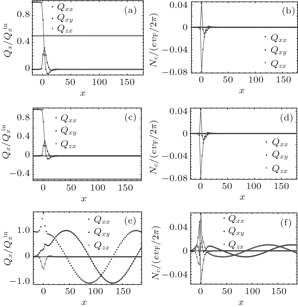 | Fig. 3. Typical spin transfer pattern in N = 19-ZGNR and N = 20-AZGNR, with exchange splitting 200vFħ /e meV. (a) ZGNR spin current at ε for N = 19; (b) ZGNR spin transfer torque at ε for N = 19; (c) ZGNR spin current at − ε for N = 19; (d) ZGNR spin transfer torque at − ε for N = 19; (e) ZGNR spin current at ε for N = 20; (f) ZGNR spin transfer torque at ε for N = 20. Each panel illustrates spin current or transfer torque in three spin directions induced by a charge current in the x direction. Results of electron-like incident state at ε = 50vFħ /e meV and hole-like state at − ε for ZGNR are shown in (a, b) and (c, d), respectively. For AZGNR, we only show electron-like states since there is no qualitative difference from hole-like states. |
In contrast, the spin filter is absent in AZNGR (Fig. 3(e)) since both spin channels are PCCs within the range of proximity splitting. The magnetic field also causes splitting in the Fermi surface, which leads to the distinct velocity of spin-up and spin-down transmission states. Therefore, the transmitted spin current precesses in the magnetic field. Owing to conservation of the z component of spin current through the interface, this precession is mostly in-plane, leading to a flat line in the z direction of spin current, except for the case near the interface, where spin accumulates. Consequently, spin transfer torque is not a constant in the far right terminal, which is formed in a similar oscillating pattern retarded to the spin current. Furthermore, if we tune chemical potential higher or lower outside of splitting, both spin channel in ZNGR or AZNGR are PCCs, which results in rapid in-plane precession, making it harder to distinguish ZGNR and AZNGR.
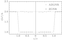
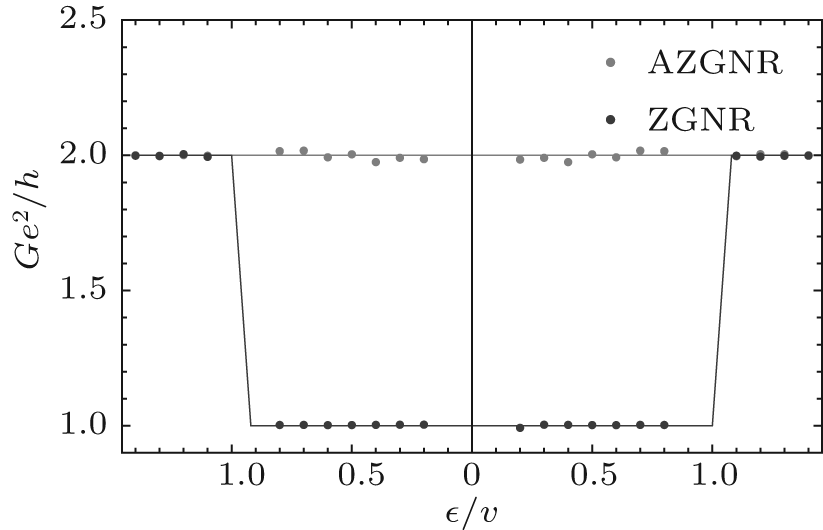 | Fig. 4. Conductance of N = 19-ZGNR in blue line and N = 20-AZGNR in green line via theoretical prediction. Numerical result is labelled in point. |
The spin transfer in the ZNGR and AZGNR has qualitatively different behavior in a low energy regime, which can be shown from conductance. Due to the absence of one spin transport channel, the conductance of ZNGR contains a sink with equal width to the exchange splitting. The width of this region alone displays the splitting intensity. This feature can help us to measure the proximity splitting. We can survey the spin filter via spin polarization on the figure. Along the bottom of this sink, non-zero spin polarization flips from spin-down (p = − 1) to spin-up (p = 1) at the interface, which identifies two spin-filter patterns in this energy range.
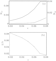
 | Fig. 5. Profile of energy-associated spin transfer torque and frequency for electron-like incident current. The energy is measured in 100vFħ /e meV within the same exchange splitting. (a) Energy-associated spin transfer torque at the interface for N = 19-ZGNR; (b) Frequencies of spin precession versus Fermi energy for N = 20-AZGNR. |
The energy-associated spin transfer torque of ZGNR and spin current frequencies of AZGNR are shown in Fig. 5. The torque is measured in the same unit system as in Fig. 3. The spin-precession frequency is defined as the inverse of precession periodicity. In close vicinity of interface of ZGNR junction, the peaks of spin transfer torque, along two transverse directions x and y, are illustrated in Fig. 5(a). In both transverse directions, the torque rises with the Fermi energy, mainly due to a stronger incident current detected at higher energy level, until it reaches its maximum value. For ZGNR, frequencies of spin precession in ferromagnetic graphene nanoribbon becomes lower when the energy of the electron in the incident terminal is higher. This happens because the itinerant electrons get higher energy and thus propagate faster than low-energy ones. Furthermore, spin accumulates in the vicinity of the interface because of band bending of the two ribbons attaching the interface.
We study the spin transport in a normal/ferromagnetic junction constructed by two semi-infinite zigzag edge graphene nanoribbons, which induced by magnetic proximity effect. Since each spin transport channel is either a perfect conducting or non-conducting channel, we identify spin-filter mechanism in symmetric ZGNR junction and spin precession in antisymmetric AZNGR junction. This gives rise to qualitatively the different spin transfer pattern in each junction. Due to this feature, the proximity splitting can easily be studied by analyzing the width of sink in charge conductance of ZNGR junction. The spin filter mechanism can be observed directly in the energy range within proximity splitting by measuring spin polarization. We show that the AZGNR displays energy-resolved in-plane spin precession, giving rise to similar measurable oscillating spin torque exerted on the magnetic nanoribbon. Such distinction in spin-transfer pattern may serve as a new method to distinguish symmetric and antisymmetric zigzag graphene nanoribbons, as well as offering a new way to generate pure spin current in the nano scale.
We would like to extend our greatest gratitude to our supervisor Prof. Jiang Xiao for his constant guidance and encouragement. We are also deeply debited to our group member Guo Wei, Lingjun Zhou, and Weichao Yu. Without their help, our research would never have run so smoothly.
| 1 |
|
| 2 |
|
| 3 |
|
| 4 |
|
| 5 |
|
| 6 |
|
| 7 |
|
| 8 |
|
| 9 |
|
| 10 |
|
| 11 |
|
| 12 |
|
| 13 |
|
| 14 |
|
| 15 |
|
| 16 |
|
| 17 |
|
| 18 |
|
| 19 |
|
| 20 |
|
| 21 |
|
| 22 |
|
| 23 |
|
| 24 |
|
| 25 |
|
| 26 |
|
| 27 |
|
| 28 |
|