


An improved transmitting multi-layer thin-film filter
[Zhang Yinga), b) , Qi Hong-Jia) , Yi Kuia) , Wang Yan-Zhia) , Sui Zhanc) , Shao Jian-Daa)†  ]
]
]
|
|


†Corresponding author. E-mail: jdshao@siom.ac.cn
The angular resolutions of the phase-shifted Rugate thin-film filters, the ultra-narrow bandpass filters, and a cutoff filter-combination device are discussed, and the electric field distributions of the filters are compared. The results show that the three transmitting multi-layer thin-film filters can realize the same angular resolution, but the electric field in the cutoff filter-combination device is the lowest. Because a lower electric-field distribution corresponds to a higher laser-induced damage threshold of the thin films, the cutoff filter-combination device may replace the traditional spatial filters in high power laser systems.
High-power lasers are widely used for measurements and are particularly important in health research and clinical diagnostics.[1– 6] These lasers have significant potential applications in military, industrial production, and other areas of daily life.[7, 8] The development of laser systems depends on the manufacturing improvement of optical devices, such as lenses, mirrors, and polarizers. A spatial filter is used to remove the high angular frequency components, and then improves the quality of the laser beam with an optical 4f system of two lenses and a pin-hole.[9, 10] However, this structure is complex and large. To decrease the size of the laser filter system in a high-power laser system, a new design is necessary.
Multi-layer thin film filters have been proposed, which have excellent performance, such as high angular selectivity, relative preparing feasibility, and moderate electric-field intensity. It also shows high flexibility in controlling the phase, polarization, and amplitude of electromagnetic waves. The spectral performance of the multi-layer thin films is generally sensitive to the incident angle, and a narrower bandwidth suggests a much better angular resolution. The Rugate thin films can suppress the ripple and adjust the bandwidth, [11– 18] so the design of Rugate thin films and optical resonator has been proposed.[19]
This paper studies the angular resolution and the electric field intensity of the Rugate thin-film filters and the Fabry– Perot multi-cavity ultra-narrow bandpass filters, and proposes an angular-resolution device with a combination of two cutoff filters to realize the spatial filtering function in high-power laser systems, which can largely decrease the electric-field intensity of the film and effectively improve the laser-induced damage threshold (LIDT) in the same angular resolution. The structures of the two cutoff filters are different from that of the traditional filter, and the electric-field intensity on the film is extremely effectively reduced in the applied field of the filter. So the combination of the two cutoff filters may be applied in practical laser systems.
The principle of the transmitting phase-shifted Rugate thin film filters has already been discussed.[19] In fact, the design of the transmitting phase-shifted Rugate thin film filters is based on a Fabry– Perot filter. The Rugate thin films are used as the mirror of the Fabry– Perot filter to suppress the transmitting ripples and achieve sharp and smooth transitions from the pass band to the stop band of the filter. The left and the right portions of the two Rugate films consist of a Fabry– Perot space layer that selects the angular spectrum. Figure 1 shows that the monochromatic plane wave is oblique incident upon the Rugate phase shift film, and a schematic diagram of transmission and reflection is given.
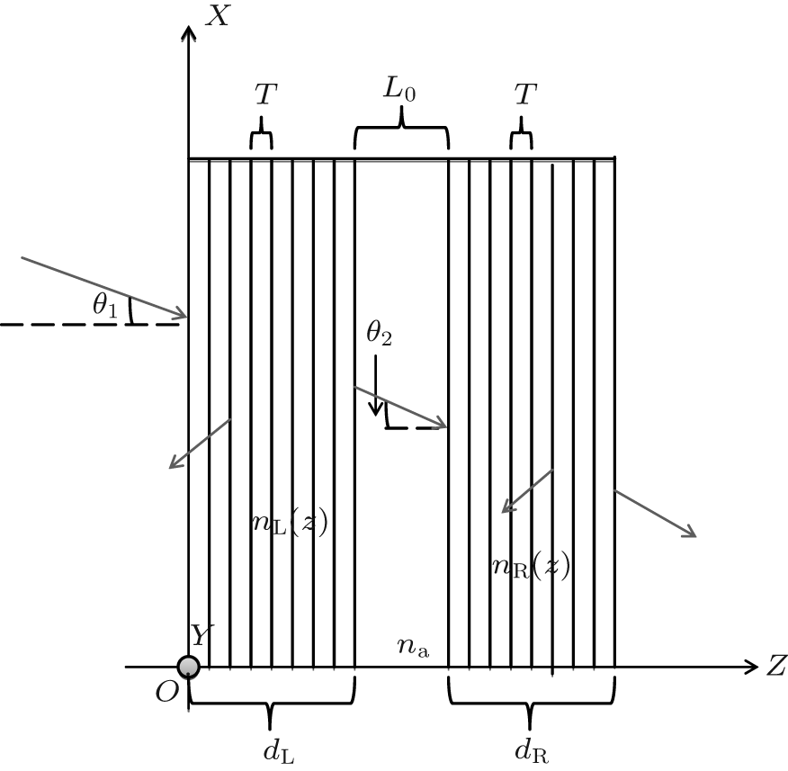 | Fig. 1. Schematic diagram of the transmission and reflection of a monochromatic plane wave on a phase-shifted Rugate spatial filter. |
The refractive index is expressed as


where np is the difference of the refractive index between the left and the right sides of the phase-shift film, Φ GL and Φ GR are the initial phases of the left and the right sides of the film, respectively, K denotes the grating’ s vector, whose module is 2π /T, dL and dR represent the left and right side film thicknesses, respectively, L0 represents the equivalent optical path causing phase hop, n0 and nG represent the refractive indices of the air and the substrate, respectively, and nL(z) and nR(z) denote the refractive indices of the left and the right films, respectively.
The transmittance spectrum and the angular spectrum of the phase-shift Rugate thin film spatial filter are calculated according to the parametric value of simulation phase-shift Rugate coating, which is listed in Table 1.
| Table 1. Parametric value of simulation phase-shift Rugate coating. |
In this study, we mainly analyze the relationship between the angular resolution and the electric-field intensity of the transmission filter and the period number of the film at different incidence angles. The film angular resolution is defined as the full-width at half maximum (FWHM) of the angular spectrum.
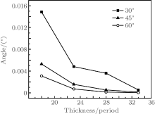
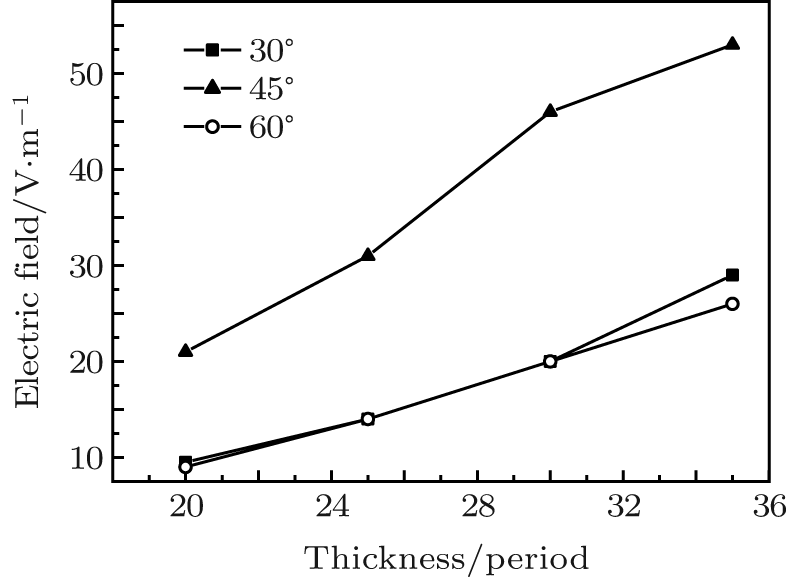
Figure 2 shows the angular resolutions of the transmitting phase-shifted Rugate thin film filters with different period numbers (n = 20, 25, 30, 35) at oblique angles of incidence (30° , 45° , and 60° ) and wavelength of 1064 nm. The angular resolution of the thin film increases with increasing oblique angles of incidence and period numbers of the left and right mirrors.
 | Fig. 2. Angular resolutions of transmitting phase-shifted Rugate thin-film filters with different period numbers (n = 20, 25, 30, 35) at oblique angles of incidence (30° , 45° , and 60° ). |
Figure 3 shows the electric field distributions of the transmitting phase-shift Rugate thin film filters with different period numbers (n = 20, 25, 30, 35) at oblique angles of incidence (30° , 45° , and 60° ). The electric field increases with increasing oblique angles of incidence and period numbers of the left and right mirrors. The filter with the best angular resolution shows the strongest electric field, up to 2.25 × 10⁷ V/m. The weakest electric field is 86 V/m.
 | Fig. 3. Electric field distributions of transmitting phase-shift Rugate thin film filters with different period numbers (n = 20, 25, 30, 35) at oblique angles of incidence (30° , 45° , and 60° ). |
The filter bandwidth depends on the ratio of the equivalent refractive high- and low-index layers at normal incidence according to the basic principle of the multi-layer thin films. The ratio of the equivalent refractive high- and low-index layers increases for an S-polarized wave and decreases for a P-polarized wave at the oblique incidence. Therefore, the oblique incidence can be used to decrease the filter bandwidth and improve the angular resolution.
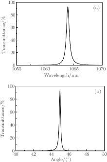
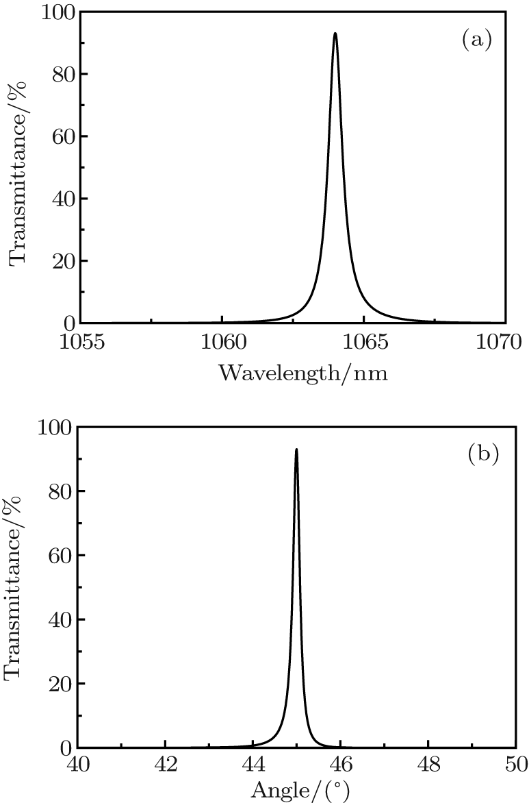
Stacks of transmitting ultra-narrow bandpass filters are indicated as sub| (HL)nH2L(HL)nHL(HL)nH2L(HL)nH| air, where sub denotes the substrate, and H and L denote Nb2O5 (2.20) and SiO2 (1.45) layers of the optical thickness of one-quarter wavelength at the wavelength of 1064 nm, respectively. The n can be 4, 6, 9, and 12. Figure 4 shows the transmittance spectrum and the angular spectrum of the transmitting ultra-narrow bandpass filter with n = 9 at oblique angle of incidence 30° .
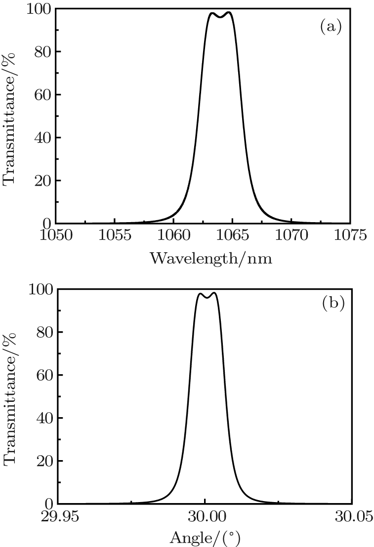 | Fig. 4. (a) Transmittance spectrum and (b) angular spectrum of the transmitting ultra-narrow bandpass filter with n = 9 at oblique angle of incidence 30° . |
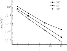
Figure 5 shows the angular resolutions of the designed transmitting ultra-narrow bandpass filters with different periods (n = 4, 6, 9, 12) at oblique angles of incidence (30° , 45° , and 60° ). The angular resolution of the thin-film filters increases with the increasing oblique angle of incidence and period number of the film.
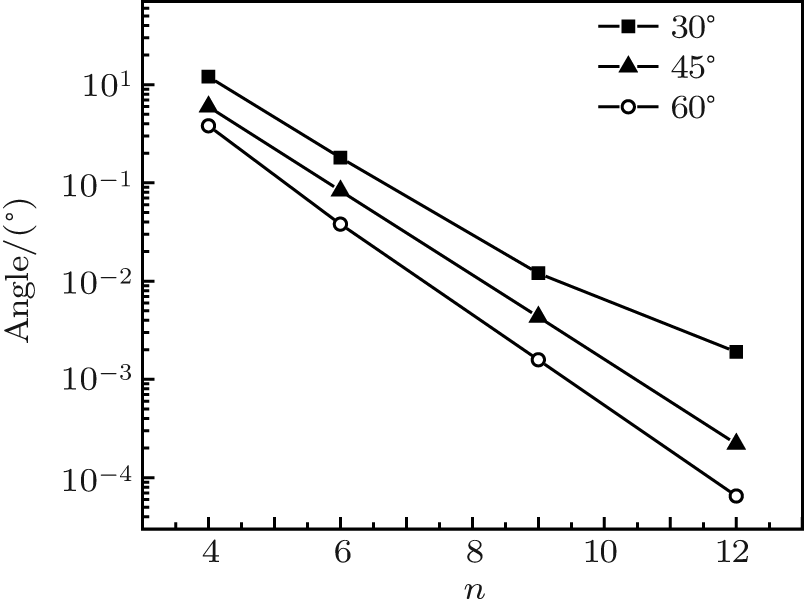 | Fig. 5. Angular resolutions of designed transmitting ultra-narrow bandpass filters with different period numbers (n = 4, 6, 9, 12) at oblique angles of incidence (30° , 45° , and 60° ). |
Figure 6 shows the electric-field distributions of the designed transmitting ultra-narrow bandpass filters with different periods (n = 4, 6, 9, 12) at oblique angles of incidence (θ = 30° , 45° , and 60° ). The electric field increases with increasing oblique angle of incidence and period number of the double-cavity filter. The strongest electric field at the central wavelength of 1064 nm is 8 × 10⁵ V/m, and the weakest one is 57 V/m.
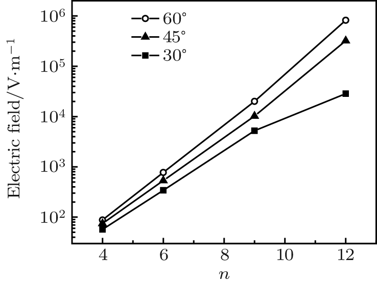 | Fig. 6. Electric-field distributions of transmitting ultra-narrow bandpass filters with different period numbers (n = 4, 6, 9, 12) at oblique angles of incidence (30° , 45° , and 60° ). |
Usually, the electric-field intensity in transmission ultra-narrowband filters is very high, so the laser-induced damage threshold can be greatly decreased. To overcome this problem, we propose a new design of combination device. In the traditional filters, the phase-shifted Rugate thin-film filters and the narrow-bandpass filters can use a transmission band, but the steep side of the minus filters can be used (Fig. 7). Shoulder points A and B have high transmittance near the stopband. The transmitting spectrum of the filter causes a blue shift of the center wavelength with increasing incident angle. If one increases the incident angle, point A shifts to stop the band region of the filter. This type of transmitting filter can block the wave with more oblique incidence. Point B works similarly, except that it blocks the wave with lower oblique incidence. Short and long wave-pass filters are used in the cases of points A and B, respectively, to obtain high transmittance.
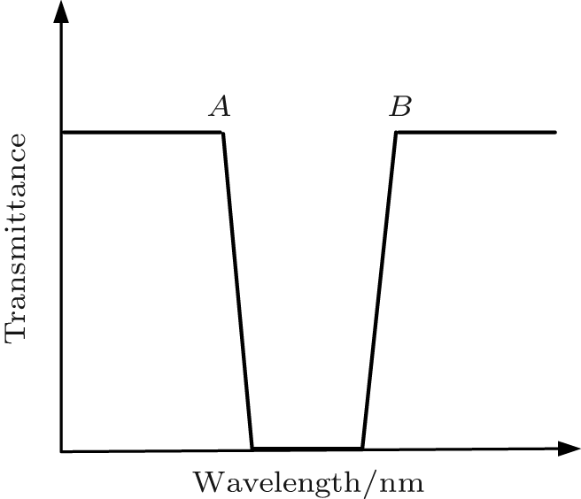 | Fig. 7. Schematic diagram of the transmission spectrum of the minus filters. |
Points A and B are located at a wavelength of 1064 nm for the filter working at the same wavelength. Figures 8(a) and 8(b) show the transmission spectra of the short wave-pass and the long wave-pass filters, respectively. Figure 8(c) is the combination transmission spectrum of the short and long wave-pass filters at a central wavelength of 1064 nm. The filter spectrum undergoes a blue or red shift for greater or less incident angle, and the wave is blocked except for the working incident angle. Therefore, the combined device of short wave-pass and long wave-pass filters presents the angular selectivity. The angular resolution of the filter is defined as the full-width at half maximum (FWHM) of the angular spectrum of the cutoff filter-combination device.
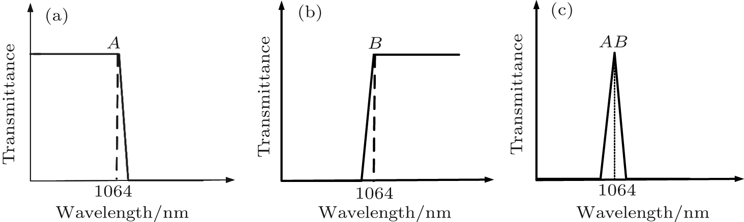 | Fig. 8. Transmission spectra of (a) short wave-pass, (b) long wave-pass, and (c) cutoff filter-combination filters. |
Figure 9 illustrates the schematic experimental setup of the combination device. Long and short wave-pass cutoff filters are inserted into the laser cavity in parallel with angle θ to the normal of the reflector mirror M. The oblique incidence beam is generated with the incident angle of 90° − θ for the long and the short-wave-pass cutoff filters. Sample 2 blocks the wave with less oblique incident angle, whereas the transmitting wave with greater oblique incident angle is blocked by sample 1. The incident angle is generally set to 45° .
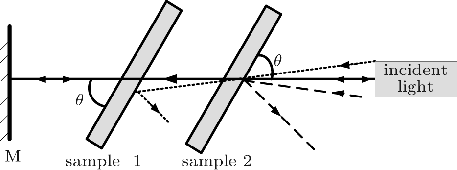 | Fig. 9. Schematic diagram of the experimental setup, where M is the reflector mirror; sample 1 is the long wave-pass cutoff filter, and sample 2 is the short wave-pass cutoff filter. |
The cutoff filter-combination device is designed with the following starting layer structures: glass/(HL)n/air, where n is the period number, and H and L are the quarter-wave layers of Nb2O5 and SiO2, respectively. The reference wavelength of the long wave-pass filter is slightly shorter than that of the short wave-pass filter.
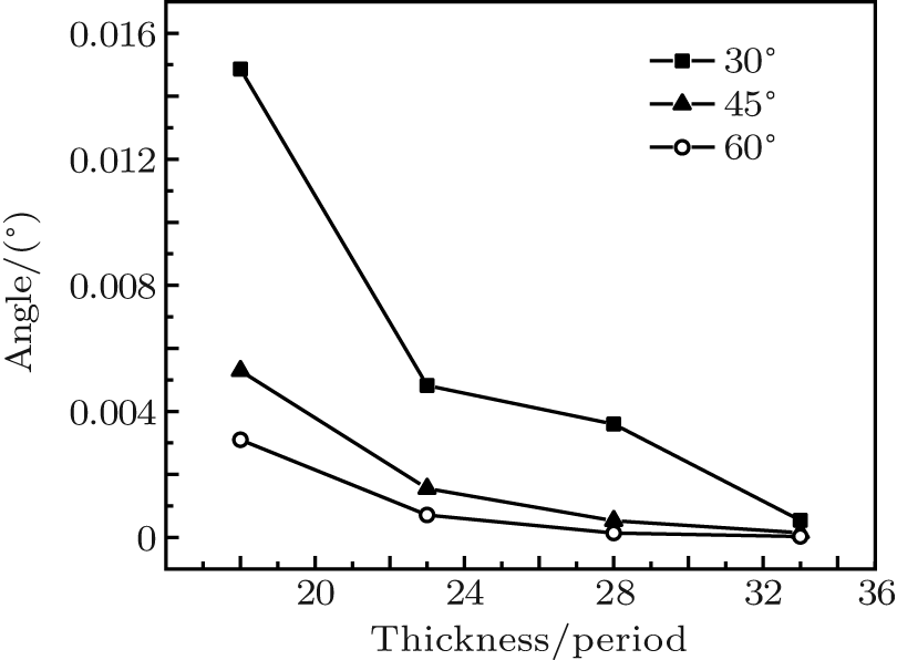
Figure 10 shows the angular resolution of the short and long wave-pass cutoff filter-combination device with different period numbers (n = 20, 25, 30, 35) and oblique angles of incidence (30° , 45° , and 60° ). The best angular resolution is 0.38° with a period number of 35 and an oblique angle of incidence of 45° .
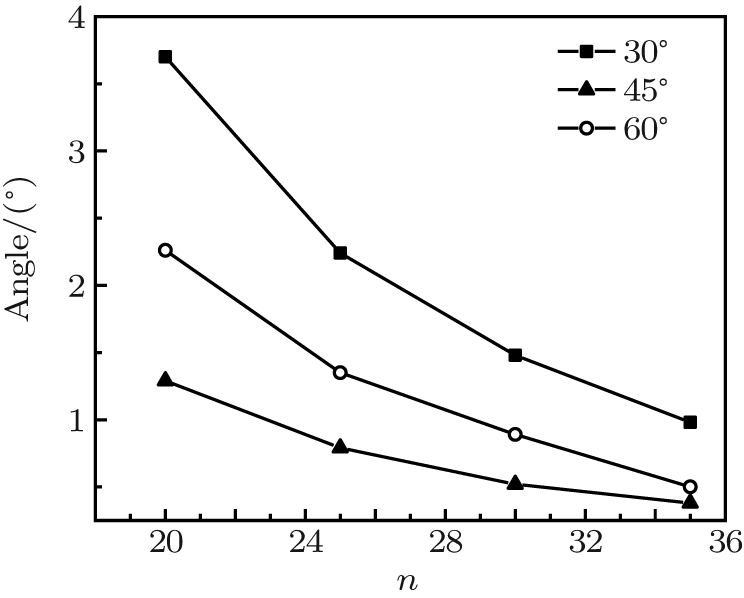 | Fig. 10. Angular resolution of short and long wave-pass cutoff filter-combination device with different period numbers (n = 20, 25, 30, 35) and oblique angles of incidence (30° , 45° , and 60° ). |
Figure 11 shows the electric field in the short and long wave-pass cutoff filter-combination device. The electric field corresponds to a period number of 35 and an oblique angle of incidence of 45° . The electric field is only 22 V/m at the central wavelength of 1064 nm.
 | Fig. 11. Electric field in short and long wave-pass cutoff filter-combination device with different period numbers (n = 20, 25, 30, 35) and oblique angles of incidence (30° , 45° , and 60° ). |
We apply the local optimization method to determine the best design of the short and long wave-pass cutoff filter-combination device. The front and back layers of the thin films are optimized, and the electric field distribution of the final design is obtained using TFCalc software (Fig. 12). The maximum electric field decreases from 50 V/m to 11 V/m, which is conducive to controlling the angular resolution of the film.
 | Fig. 12. Electric-field distribution of short and long wave-pass cutoff filter-combination device with a period number of 35 and an oblique angle of incidence of 45° : (a) before local optimization and (b) after local optimization. |
Figure 13 shows the transmission and angular spectra of the short and long wave-pass cutoff filter-combination device with a period number of 35 and an oblique angle of incidence of 45° after locally optimizing at a central wavelength of 1064 nm. An angular spectrum ranging from θ − 0.19° to θ + 0.19° is allowed to pass in the experiment, whereas the others are filtered. This process is used to select the angular spectrum.
 | Fig. 13. (a) Transmission and (b) angular spectra of short and long wave-pass cutoff filter-combination device with a period number of 35 and an oblique angle of incidence of 45° after local optimization. |
The phase-shifted Rugate thin-film filters, the ultra-narrow bandpass filters, and the short and long wave-pass cutoff filter-combination device can realize the same angular resolution, while the electric field intensities in these filters are quite different. For example, when the angular resolution of the three kinds of thin-film filters is set to 0.5° , the corresponding maximum electric field intensities are 300 V/m, 100 V/m, and 6 V/m, respectively. These data indicate that the electric field in the combined device is much lower than that in the phase-shifted Rugate thin-film filters and the ultra-narrow bandpass filters. The combined device has no resonance and does not yield a resonance field in the thin films, so the electric field intensity is greatly reduced. The electric field in the thin films is closely related to the laser-induced damage threshold, and the temperature field is also greatly reduced. So the laser-induced damage threshold of the thin films is improved in the high angular resolution laser system. Therefore, the combined device of long wave-pass and short wave-pass filters is promising to replace the large-size spatial filters in high-power laser systems.
We first analyze the angular resolution of the transmitting thin-film filters with different oblique angles of incidence and period numbers. The feasibility of the filter-combination device applied in a high power laser system is analyzed by comparing the electric field distributions of the filters. The results show that the filter-combination device exhibits a low electric-field intensity. When the local optimization design is adopted in the short and long wave-pass cutoff filter-combination device, the electric field inside the film can be further reduced. The device combining short and long wave-pass cut-off filters can potentially replace the large-size spatial filters in high power laser systems. Future studies should focus on realizing several excellent angle-resolution thin-film filter designs.
| 1 |
|
| 2 |
|
| 3 |
|
| 4 |
|
| 5 |
|
| 6 |
|
| 7 |
|
| 8 |
|
| 9 |
|
| 10 |
|
| 11 |
|
| 12 |
|
| 13 |
|
| 14 |
|
| 15 |
|
| 16 |
|
| 17 |
|
| 18 |
|
| 19 |
|