

Controllable optical response in hybrid opto-electromechanical systems*
[Jiang Chenga)†  , Cui Yuan-Shun
a) , Liu Hong-Xianga), b) , Li Xiao-Weia) , Chen Gui-Bina) ]
, Cui Yuan-Shun|
|


†Corresponding author. E-mail: chengjiang8402@163.com
*Project supported by the National Natural Science Foundation of China (Grant Nos. 11304110 and 11174101), the Natural Science Foundation of Jiangsu Province, China (Grant Nos. BK20130413 and BK2011411), the Natural Science Foundation of the Jiangsu Higher Education Institutions of China (Grant No. 13KJB140002).
We theoretically investigate the analog of electromagnetically induced absorption and parametric amplification in a hybrid opto-electromechanical system consisting of an optical cavity and a microwave cavity coupled to a common mechanical resonator. When the two cavity modes are driven by two pump fields, a weak probe beam is applied to the optical cavity to monitor the optical response of the hybrid system, which can be effectively controlled by adjusting the frequency and power of the two pump fields. We find that the analog of electromagnetically induced absorption and parametric amplification can appear in the probe transmission spectrum when one cavity is pumped on its red sideband and another is pumped on its blue sideband. These phenomena can find potential applications in optical switching and signal amplification in the quantum information process.
The rapidly developing research field of cavity optomechanics explores the nonlinear coupling between the electromagnetic and mechanical systems via radiation pressure, which allows for quantum control of the mechanical motion with light, and at the same time, controlling the optical response of optomechanical systems due to mechanical interactions.[1– 4] Depending on the frequency of the electromagnetic field, the fields of optomechanics and electromechanics have witnessed remarkable progress both in optical and microwave domains, including quantum ground state cooling of the nanomechanical resonators, [5, 6] quantum coherent coupling between light and mechanical degrees of freedom, [7, 8] normal-mode splitting, [9, 10] and opto-/electromechanically induced transparency (OMIT/EMIT).[11– 16] OMIT/EMIT is the analog of electromagnetically induced transparency (EIT), [17, 18] which has been first observed in atomic vapors[19] and has recently been observed in various solid state systems, such as quantum wells[20] and nitrogen-vacancy centers.[21] Likewise, OMIT/EMIT can be utilized for slowing or advancing electromagnetic signals, [13, 22] and for information storage and retrieval in long-lived oscillations.[23] In addition, the phenomena of electromechanically induced absorption (EMIA)[24] and amplification[25] with a blue-detuned pump field have also been demonstrated in a circuit nano-electromechanical system that consisted of a superconducting microwave resonator and a nanomechanical beam. Singh et al. have also demonstrated similar phenomena based on the optomechanical coupling between a graphene mechanical resonator and a superconducting microwave cavity.[26]
More recently, the ability of a mechanical resonator to couple to electromagnetic cavities of vastly different wavelengths has led to intensive investigation of double-cavity optomechanical systems. Such systems can serve as an interface to realize coherent transfer between two optical wavelengths, [27– 29] and between the microwave and optical domains.[30, 31] Bochmann et al. have demonstrated a nanomechanical interface between optical photons and microwave electrical signals using a piezoelectric photon crystal, where they observed electromechanically induced optical transparency.[32] In addition, by combing the technologies of electromechanics and optomechanics, Andrews et al. have successfully coupled a nanomechanical resonator to both a superconducting microwave cavity and an optical cavity, [33] which consists of a hybrid opto-electromechanical system.[34, 35] They experimentally demonstrated reversible and coherent conversion between microwave and optical light, which can find vital applications in modern communications networks. Li et al. have studied effective beam-splitter-like and two-mode-squeezing photon– photon interactions in this optomechanical interface by employing largely detuned driving lasers.[36] In the present paper, we investigate the optical switching between the analog of electromagnetically induced absorption and amplification in this hybrid system in the simultaneous presence of two strong pump beams and a weak probe beam. It should be noted that Qu and Agarwal have theoretically shown the existence of an absorption peak within the transparency window in the same double-cavity configuration when both cavities are driven at their respective red sidebands.[37] However, the regime, where the decay rate of the optical cavity κ o is larger than the damping rate the mechanical resonator γ m that is then larger than the decay rate of the microwave cavity κ e (i.e., κ o > γ m > κ e), should be reached to enable this phenomenon. This regime has seldom be realized in current experiment. Recently, Nunnenkamp et al. have explored for the first time the reversed dissipation regime, where the mechanical energy relaxation rate exceeds the energy decay rate of the electromagnetic cavity, which allows for mechanically-induced amplification of the electromagnetic mode.[38] Here, using the experimentally realizable parameters, [33] we show that the analog of electromagnetically induced absorption (EIA)[39] and amplification can exist when one cavity is driven by a blue-detuned pump field and another is driven at its red sideband. Therefore, we can switch conveniently from EIA to parametric amplification or vice versa by changing the power of the pump fields. This hybrid system could be utilized to realize quantum-limited amplification with unlimited gain-bandwidth product.[40]
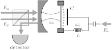
A schematic of the hybrid opto-electromechanical system is shown in Fig. 1, where a microwave cavity and an optical cavity are coupled to a common nanomechanical resonator. The optical cavity with resonance frequency ω o is driven by a strong pump beam Eo with frequency Ω o and a weak probe beam Ep with frequency Ω p simultaneously. The microwave cavity with resonance frequency ω e, denoted by equivalent inductance L and equivalent capacitance C, is only driven by a strong pump beam Ee with frequency Ω e. In a rotating frame at the pump frequency Ω o and Ω e, the Hamiltonian of the hybrid system reads H = H0+ Hint+ Hdrive, [12, 30, 31] where
Here, operators a, b, and c are the annihilation operators the of optical cavity, microwave cavity, and mechanical resonator, respectively. Δ o = ω o− Ω o and Δ e = ω e− Ω e are the corresponding cavity-pump field detunings. ω m is the resonance frequency of the mechanical resonator with damping rate γ m. go (ge) is the single-photon coupling rate between the mechanical mode and the optical (microwave) cavity mode. Hdrive describes the interaction between the input fields and the cavity fields, where Eo, Ee, and Ep are related to the power of the applied fields by 

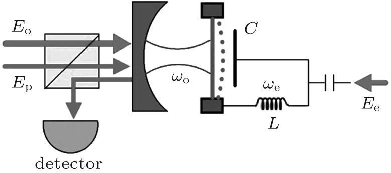 | Fig. 1. Schematic diagram of the hybrid opto-electromechanical system. A mechanical resonator c couples to both an optical cavity modes a and a microwave cavity mode b denoted by the equivalent inductance L and equivalent capacitance C. The optical cavity is driven by a strong pump beam Eo in the simultaneous presence of a weak probe beam Ep while the right cavity is only driven by a pump beam Ee. |
According to the Heisenberg equations of motion and the commutation relation [a, a† ] = 1, [b, b† ] = 1, and [c, c† ] = 1, the temporal evolutions of operators a, b, and Q (Q = c† + c) can be obtained. In addition, by introducing the corresponding noise and damping terms for the cavity and mechanical modes, we derive the quantum Langevin equations as follows:


where ain and bin are the input vacuum noise with zero mean value and ξ is the Brownian stochastic force with zero mean value.[42] We derive the steady-state solution to Eqs. (2)– (4) by setting all of the time derivatives to zero, which are given by
where 


where we have identified all operators with their expectation values and dropped the quantum and thermal noise terms.[12] The nonlinear terms δ a† δ a, δ b† δ b, δ aδ Q, and δ bδ Q can result in some interesting phenomena of optomechanical systems, such as second and higher-order sidebands.[43] When the pump power is strong enough, | as| ≫ 1 and | bs| ≫ 1. Therefore, one can safely neglect these nonlinear terms in the linearized equations (6)– (8).[42] In order to solve Eqs. (6)– (8), we make the ansatz[44] 〈 δ a〉 = a+ e− iδ t+ a− eiδ t, 〈 δ b〉 = b+ eiδ t+ b− eiδ t, and 〈 δ Q〉 = Q+ e− iδ t+ Q− eiδ t. By substituting the above ansatz into Eqs. (6)– (8), we can obtain the following solution:
where
Here, no = | as| 2 and ne = | bs| 2, approximately equal to the number of pump photons in each cavity, are determined by the following coupled equations:

The output field from the cavity can be obtained by using the standard input– output theory:[12, 45]
We can see from Eq. (13) that the output field contains two input components (Ω o and Ω p) and one generates four-wave mixing (FWM) component at the frequency 2Ω o− Ω p. Defining the transmission of the probe field as the ratio of the output and input field amplitudes at the probe frequency, [12] we have
To demonstrate the numerical results, we consider for illustration an experimentally realizable hybrid opto-electromechanical system. The parameters used are:[5, 14, 33]ω o = 2π × 282 THz, ω e = 2π × 7.1 GHz, κ o = 2 π × 1.65 MHz, κ e = 2π × 1.6 MHz, κ o, ext = 0.76κ o, κ e, ext = 0.11κ e, go = 2π × 27 Hz, ge = 2π × 2.7 Hz, ω m = 2π × 5.6 MHz, and γ m = 2π × 4 Hz.
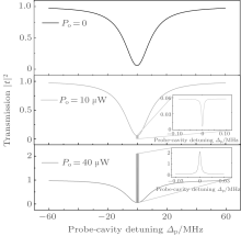
The optical response of this hybrid system is characterized by the transmission of the probe laser beam under the influence of two pump beams. We first consider the situation where the optical cavity mode is pumped on its blue sideband, while the microwave cavity is pumped on its red sideband, i.e., Δ o= − ω m and Δ e= ω m. In Fig. 2, the probe transmission | t| 2 is plotted as a function of the probe-cavity detuning Δ p = Ω p− ω o for Po= 0, 10, and 40 μ W, respectively. When the pump field is off, the probe transmission spectrum shows the usual Lorentzian line shape of the bare cavity, which can be seen from Fig. 2(a). However, when Po = 10 μ W, we can see that the cavity transmission is reduced in the resonant region compared with bare cavity minimum (Po = 0), which is referred to as the analog of the EIA. At even higher pump power, Po = 40 μ W for example, the system switches from EIA[13, 24] to parametric amplification, [25] where the probe transmission can be amplified significantly. In this case, the hybrid system can be used as a transistor[46] to amplify the weak optical or microwave signal. These phenomena can be understood in terms of constructive interference. The simultaneous presence of pump and probe fields induces a modulation at the beat frequency δ = Ω p− Ω o of the radiation pressure force acting on the common mechanical resonator. When this modulation is close to the mechanical resonance frequency ω m, the mechanical mode starts to oscillate coherently, giving rise to Stokes (Ω s = Ω o− ω m) and anti-Stokes (Ω as = Ω o+ ω m) scattering of light from the strong pump field. If the optical cavity is driven on its blue sideband (Δ o = ω o− Ω o = − ω m), then the highly off-resonant anti-Stokes scattering is suppressed and only the Stokes scattering builds up within the cavity. When the probe field is resonant with the optical cavity (Ω p = ω o = Ω o− ω m), constructive interference between the Stokes field and the probe field enhances the build-up of the intra-cavity probe field. The resulting increased feeding of probe photons into the cavity manifests itself as a reduced cavity transmission. When the pump power is strong enough, the number of down-converted pump photons is much larger than the probe photons sent to the cavity, and the probe transmission can exceed unity because of the parametric amplification of the probe beam by the hybrid opto-electromechanical system.
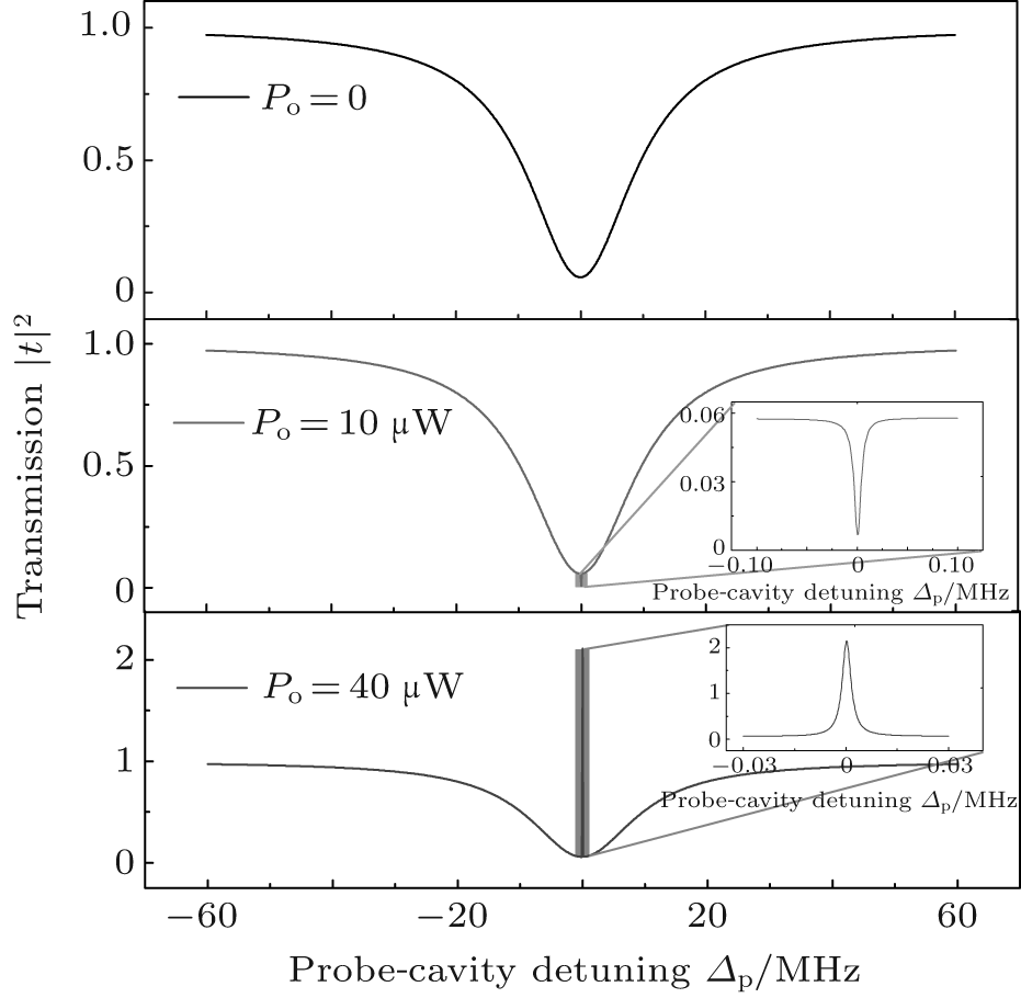 | Fig. 2. Probe transmission | t| 2 versus probe-cavity detuning Δ p = Ω p− ω o for Po = 0, 10, and 40 μ W, respectively. Here, the optical cavity is pumped on its blue sideband and the microwave cavity is pumped on its red sideband, i.e., Δ o = − ω m and Δ e = ω m. The inset of Figs. 2(b) and 2(c) show the probe transmission near the resonant region on an enlarged scale. Other parameters are Pe = 1 μ W, ω o = 2π × 282 THz, ω e = 2π × 7.1 GHz, κ o = 2π × 1.65 MHz, κ e = 2π × 1.6 MHz, κ o, ext = 0.76κ o, κ e, ext = 0.11κ e, go = 2π × 27 Hz, ge = 2π × 2.7 Hz, ω m = 2π × 5.6 MHz, and γ m = 2π × 4 Hz. |
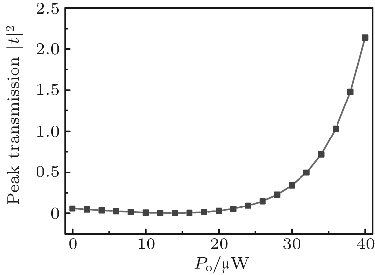 | Fig. 3. Peak probe transmission | t| 2 at the cavity resonance as a function of the optical pump power Po when Δ o = − ω m and Δ e = ω m. The microwave pump power Pe is equal to 1 μ W. Other parameters are the same as those of Fig. 2. |
The peak probe transmission | t| 2 versus the pump power is plotted in Fig. 3. It can be seen that the peak probe transmission decreases from a value for the bare cavity minimum (Po = 0) to a minimum value with the increasing pump power, representing the analog of EIA. By increasing the pump power further, the probe transmission begins to increase gradually and exceeds the initial value for the bare cavity. When the pump power is above about 37 μ W, | t| 2 > 1, the hybrid system enters the regime of parametric amplification, where the probe beam can be amplified significantly. Therefore, we can switch conveniently between EIA and parametric amplification by adjusting the power of the pump field.
 | Fig. 4. Probe transmission | t| 2 as a function of the probe-cavity detuning Δ p = Ω p− ω o when Δ o = ω m and Δ e = − ω m for Pe = 0, 20, 40, 60 nW, respectively. The inset shows the peak transmission as a function of the microwave pump power Pe when the probe field is resonant with the optical cavity. The optical pump power Po equals 5 μ W. Other parameters are the same as those of Fig. 2. |
The hybrid opto-electromechanical system enables more controllability of the optical response to the weak probe field. In the following, we consider the situation where the optical cavity is driven on its red sideband while the microwave cavity is driven on its blue sideband (Δ o = ω m, Δ e = − ω m). In Fig. 4, we plot the probe transmission | t| 2 as a function of the probe-cavity detuning Δ p for Pe = 0, 20, 40, 60 nW, respectively. When the microwave pump field is off, the radiation pressure of the microwave cavity on the mechanical resonator is negligible, and the hybrid system operates like a typical single cavity optomechanical system. Here the optical pump power is 5 μ W, and we can see that the probe transmission in the resonant region is nearly unity. The phenomenon of optomechanically induced transparency appears in this case, and the transparency window can be further broadened by increasing the optical pump power. However, if we turn on the microwave pump field, then the transmission of the probe field can exceed unity. For example, the transmitted probe field can be amplified by about 150% when Pe = 20 nW. The inset of Fig. 4 shows that the peak transmission of the probe field can be enhanced by increasing the pump power. The reason for this phenomenon can be explained as follows. When the microwave cavity is pumped on its blue sideband, the pump photons are converted to phonons and cavity photons by the Stokes process, leading to heating of the mechanical resonator. The generated phonons are then absorbed by the anti-Stoke process in the optical cavity driven on its red sideband. The increasing microwave pump field coherently enhances the vibration of the mechanical oscillator, leading to the parametric amplification of the probe field. Based on the above discussions, we can see that the optical response of this hybrid system can be effectively controlled by tuning the frequency and power of the two pump fields.
In conclusion, we have studied the mechanically-mediated optical response of a hybrid opto-electromechanical system that consisted of an optical cavity and a microwave cavity coupled to a common mechanical resonator. When the optical cavity is driven by a blue-detuned pump field and the microwave cavity is driven at its red sideband, constructive interference between the Stokes field and the probe field leads to the analog of electromagnetically induced absorption and parametric amplification, which can be switched from one to another easily by controlling the power of the optical pump field. Furthermore, when the optical cavity is driven by a red-detuned pump field and the microwave cavity is driven by a blue-detuned pump field, the microwave pump field can be used as a switch between optomechanically induced transparency and parametric amplification.
| 1 |
|
| 2 |
|
| 3 |
|
| 4 |
|
| 5 |
|
| 6 |
|
| 7 |
|
| 8 |
|
| 9 |
|
| 10 |
|
| 11 |
|
| 12 |
|
| 13 |
|
| 14 |
|
| 15 |
|
| 16 |
|
| 17 |
|
| 18 |
|
| 19 |
|
| 20 |
|
| 21 |
|
| 22 |
|
| 23 |
|
| 24 |
|
| 25 |
|
| 26 |
|
| 27 |
|
| 28 |
|
| 29 |
|
| 30 |
|
| 31 |
|
| 32 |
|
| 33 |
|
| 34 |
|
| 35 |
|
| 36 |
|
| 37 |
|
| 38 |
|
| 39 |
|
| 40 |
|
| 41 |
|
| 42 |
|
| 43 |
|
| 44 |
|
| 45 |
|
| 46 |
|