

Phase and direction dependence of photorefraction in a low-frequency strong circular-polarized plane wave*
[Huang Yong-Sheng† , Nai-Yan Wang, Tang Xiu-Zhang]
, Nai-Yan Wang, Tang Xiu-Zhang]
|
|


†Corresponding author. E-mail: huangyongs@gmail.com
*Project supported by the National Basic Research Program of China (Grant No. 2011CB808104) and the National Natural Science Foundation of China (Grant No. 11105233).
Contrary to the superposition principle, it is well known that photorefraction exists in the vacuum with the presence of a strong static field, a laser field, or a rotational magnetic field. Different from the classical optical crystals, the refractive index also depends on the phase of the strong electromagnetic field. We obtain the phase and direction dependence of the refractive index of a probe wave incident in the strong field of a circular-polarized plane wave by solving the Maxwell equations corrected by the effective Lagrangian. It may provide a valuable theoretical basis to calculate the polarization evolution of waves in the strong electromagnetic circumstances of pulsar or neutron stars.
In a vacuum, a photon can always metamorphose into an electron and a positron and then annihilate each other becoming a photon again within a short time mandated by the uncertainty principle. The process keeps on repeating itself. The electron and positron can also interact by exchanging a photon or more photons. Therefore, the vacuum is polarized and magnetized by strong fields and exhibits nonlinear optical characteristics.[1– 13] In a static or rotational magnetic field, the vacuum leads to birefringence[4, 5, 7, 8, 14] for the probe waves. Until now, the experimental results[5, 6] are so close to the birefringence predicted by the existing theories.[4, 7, 8] Heyl and Shaviv[5] calculated the direction dependence of the refractive index and the polarization evolution of a probe wave in a strong rotational magnetic field. Based on the Maxwell equations, accompanied with the rotational magnetic field Br, a strong rotational electric field Er exists. Due to the electric field Er, the phase velocity, the group velocity, and the refractive index of the probe wave depend on the angle between the wave vector and Er × Br and the phase of the strong electromagnetic field Br. To check the light– light diffraction experimentally, King, Piazza, and Keitel[16, 17] proposed a matterless double-slit scenario by using head-on collisions of a probe laser field with two ultra-intense laser beams. Kryuchkyan and Hatsagortsyan[9] predicted the “ brag scattering” rate of a probe wave by spatially modulated strong electromagnetic fields. The phase and direction dependence of the refractive index, the relative permittivity, and the relative permeability of a probe wave in a strong rotation electromagnetic field have not been discussed in detail, but they are significant for the calculation of the polarization evolution, which maybe helpful for observations to distinguish emissions from a pulsar and to deduce the structure of the magnetosphere.[15, 18– 20]
The photon polarization tensor is a powerful tool for describing the vacuum polarization in a homogeneity magnetic field, [21, 22] an electric field, [22] or an electromagnetic field.[23, 24] With the photon polarization tensor, researchers investigated the angle dependence of vacuum birefringence[25] in a homogeneous magnetic field, the amplitude for the scattering of a photon[26, 27] by an intense laser field, and the light diffraction.[28] However, the phase and direction dependence of photorefraction in a circular-polarized plane wave has not been discussed in detail.
Without using the photon polarization tensor, there is another simple and effective method to obtain the refractive index from the dispersion relationship by solving the Maxwell equations corrected by the effective Lagrangian 𝔏 eff[29] in a homogeneous[4, 7, 8] or slowly-varying field. By using this method, in this paper, the refractive index of a probe wave with an arbitrary incident angle in the presence of a rotational strong electric and a rotational strong magnetic field is studied. With the obtained dispersion relationship of the probe wave, the phase and direction dependence of the refractive index, the permittivity, and the permeability are calculated in detail. It may provide a valuable theoretical basis to calculate the polarization evolution of waves in the strong electromagnetic circumstances of pulsar[30] or neutron stars[19, 20, 31, 32] and to understand the atmospheric emission of neutron stars.[32– 37]
The external field is assumed to be a low-frequency strong circular-polarized electromagnetic wave,

where ϕ Ω = Ω t – krz, kr = Ω /c, the vacuum light velocity is c = 3.0 × 10⁸ m/s, and cB0 ≲ 1018 V/m, which is the critical Schwinger field of electron– positron pair production in the vacuum.
Now assume that the wave vector of the probe wave is kp = (k sin(θ )cos(ϕ ), k sin(θ )sin(ϕ ), k cos(θ )) in the rotation coordinate system (Ê r, B̂ r, ẑ ), where θ and ϕ are the angle between kp and ẑ and the angle between the projection of kp on the Ê r– B̂ r plane and Ê r, respectively.
Figure 1 shows four cases as follows. (i) There is no interaction between the parallel incident probe wave and the rotational magnetic and electric field. (ii) The refractive indices of the parallel polarized probe wave and the perpendicular polarized probe wave are 1+ 14ξ and 1 + 8ξ , respectively, with 


where ϕ 0 − π /2 is the angle between the projection of kp on the x̂ – ŷ plane and the x axis. Set
in the rotational coordinate system. Therefore, (x̂ p, ŷ p, k̂ p = kp/kp) is a new unit orthogonal basis. After some algebra, we obtain

in the laboratory system (x̂ , ŷ , ẑ ). Therefore, the electromagnetic field of the probe wave satisfies

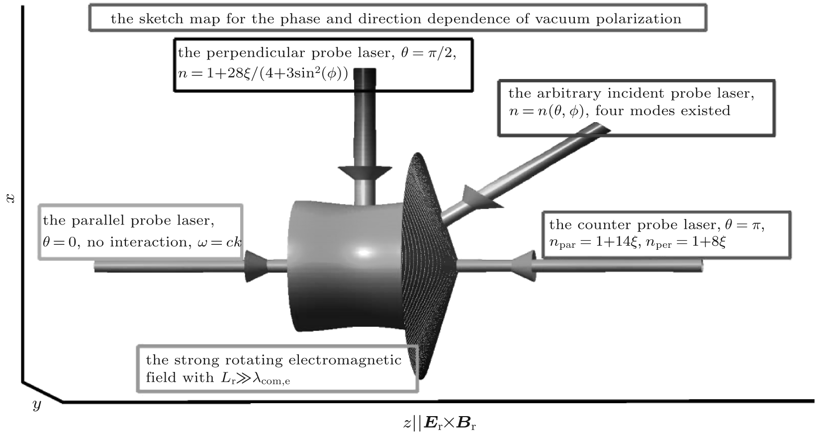 | Fig. 1. The sketch map for the phase and direction dependence of vacuum polarization of a probe wave in a strong rotating electromagnetic field with the scaling length  |
where the components in the rotational system (x̂ p, ŷ p, k̂ p) and the components in the laboratory system (x̂ , ŷ , ẑ ) satisfy the rotational transformation, 
With E3 = 0, we obtain

With the effective Lagrangian 𝔏 eff, [29] the nonclassical electric displacement field Dp = D − ε 0Er and magnetic field strength 


where the tensors ϵ r, μ – 1, r in the rotational system and those in the laboratory system satisfy ϵ r = ϵ LR and μ – 1, r = μ – 1, LR. The ϵ r and μ – 1, r are expressed as


where n = ck/ω is the refractive index.
With the wave assumption and the linearization of the Maxwell equations corrected by the effective Lagrangian 𝔏 eff, the dispersion relationship is obtained after some straightforward algebra

It contains three special cases for θ = 0, θ = π , and θ = π /2.
If θ = 0, the dispersion relationship becomes two second-order equations with roots of 1, − 1− 14ξ for the parallel polarization and roots of 1, − 1− 8ξ for the perpendicular polarization. The − 1− 14ξ and − 1− 8ξ correspond to the back-propagation waves. Therefore, there is no interaction between the forward-propagating wave and the rotational field.
If θ = π , the dispersion relationship has roots of – 1, 1 + 14ξ for the parallel polarization and roots of – 1, 1 + 8ξ for the perpendicular polarization. The refractive indices are the same as those in the static strong magnetic field.[4, 7]
If θ = π /2, the dispersion relationship becomes

therefore, the refractive index is 
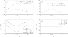
Figure 2 shows the direction dependence of the refractive indices. There are four modes for an arbitrary incident angle. The n1 satisfies n1 ≤ − 1 and decreases with increasing θ for θ ∈ [0, π /2) and increases for θ ∈ (π /2, π ]. The n2 satisfies n2 < − 1 for θ ∈ [0, π /2) and n2 > 1 for θ ∈ (π /2, π ]. The n1 and n2 cannot reach a finite value at θ = π /2. The n3 satisfies n3 ≤ 1 for θ ∈ [0, π /2) and n3 > − 1 for θ ∈ (π /2, π ], and becomes zero at θ = π /2. The n4 increases with increasing θ for ϕ ≤ 3π /4 and reaches the maximum value at θ ≈ 3π /5 for ϕ > 3π /4. For θ = π /2, 
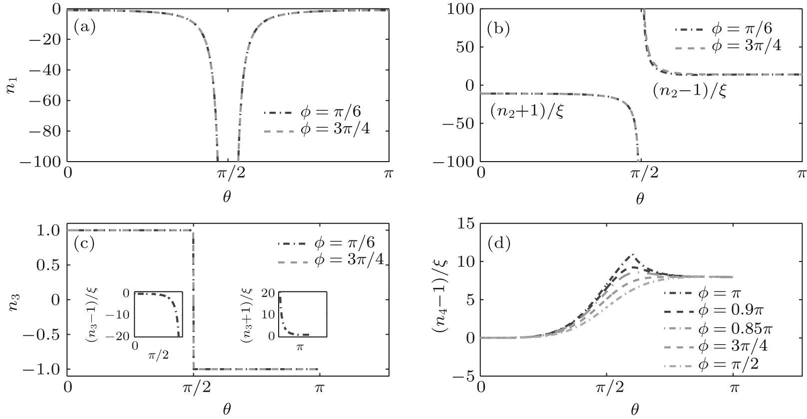 | Fig. 2. The direction dependence of the refractive indices of a probe wave in a strong circular-polarized electromagnetic field. There are four modes for θ ≠ π /2. (a) Negative n1; (b) (n2 + 1)/ξ for θ ∈ [0, π /2) and (n2 − 1)/ξ for θ ∈ (π /2, π ]; (c) n3; (d) (n4 − 1)/ξ . |
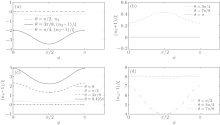
Figures 3 and 4 show the phase dependence of the refractive indices. The n1 satisfies n1 ≤ − 1 and reaches the maximum value at the axis of symmetry, ϕ = π /2. The n2 reaches the minimum (maximum) value at the symmetry axis for θ < π /2 (θ > π /2). The n3 satisfies n3 ≤ 1 and reaches the minimum value at the axis of symmetry for θ < π /2. For θ > π /2, n3 ≥ − 1 and reaches the maximum value at the axis of symmetry for θ < π /2. The n4 reaches the minimum value at the symmetry axis.
 | Fig. 3. The phase dependence of the refractive indices of a probe wave in a strong circular-polarized electromagnetic field: (a), (b) n1; (c), (d) n2. |
 | Fig. 4. The phase dependence of the refractive indices of a probe wave in a strong circular-polarized electromagnetic field: (a), (b) n3; (c), (d) n4. |
With the refractive indices and Eqs. (9) and (10), the phase dependence of the permittivity ε L and the permeability μ L corresponding to the four refractive indices can be obtained. Since the four components, 


We have obtained the dispersion relationship of a probe wave propagating in a strong circular-polarized electromagnetic field with an arbitrary incident angle. Three special cases for θ = 0, π /2, π have been discussed in detail. The phase and direction dependence of the refractive index, the permittivity, and the permeability in the laboratory system have been obtained. The relationships have some symmetries. For the perpendicular incident probe wave with θ = π /2, there is only one permissible mode with the refractive index 
Until now, in the laboratory, the tightly focused strong circular-polarized laser pulse is the only way to generate the rotating electromagnetic field. However, if the probe wave is not propagating parallel to the focused pulse, the optical path is about several micrometers. Comparing the probe wave propagating through the strong field of the pulse and a probe wave with the same frequency propagating in a vacuum without any field, the phase shift of interference fringes, Δ ϕ p, could be used to reveal the refractive index in the strong field. For a strong laser with an intensity of 1020 W/cm2, wavelength of 1 μ m and the probe wave with a wavelength of 1 μ m, we have | Br| ≈ 105 T and Δ ϕ p ≈ 10− 13. Therefore, it needs quite a precise measurement that we cannot realize currently.
We are grateful to Felix Karbstein for many interesting and enlightening discussions.
| 1 |
|
| 2 |
|
| 3 |
|
| 4 |
|
| 5 |
|
| 6 |
|
| 7 |
|
| 8 |
|
| 9 |
|
| 10 |
|
| 11 |
|
| 12 |
|
| 13 |
|
| 14 |
|
| 15 |
|
| 16 |
|
| 17 |
|
| 18 |
|
| 19 |
|
| 20 |
|
| 21 |
|
| 22 |
|
| 23 |
|
| 24 |
|
| 25 |
|
| 26 |
|
| 27 |
|
| 28 |
|
| 29 |
|
| 30 |
|
| 31 |
|
| 32 |
|
| 33 |
|
| 34 |
|
| 35 |
|
| 36 |
|
| 37 |
|