Wang Jin-Ze, Huang Qing-Li, Xu Xin, Quan Bao-Gang, Luo Jian-Heng, Zhang Yan, Ye Jia-Sheng, Li Dong-Mei, Meng Qing-Bo, Yang Guo-Zhen. Realizing high photovoltaic efficiency with parallel multijunction solar cells based on spectrum-splitting and -concentrating diffractive optical element* . Chinese Physics B, 2015, 24(5): 054201
Permissions
Realizing high photovoltaic efficiency with parallel multijunction solar cells based on spectrum-splitting and -concentrating diffractive optical element*
Wang Jin-Zea),b),c), Huang Qing-Lia),b),c), Xu Xina),b),c), Quan Bao-Ganga),d), Luo Jian-Henga),b),c), Zhang Yane), Ye Jia-Shenge), Li Dong-Meia),b),c), Meng Qing-Boa),b),c)†, Yang Guo-Zhena),f)‡
Beijing National Laboratory for Condensed Matter Physics, Institute of Physics, Chinese Academy of Sciences, Beijing 100190, China
Key Laboratory for Renewable Energy, Institute of Physics, Chinese Academy of Sciences, Beijing 100190, China
Beijing Key Laboratory for New Energy Materials and Devices, Institute of Physics, Chinese Academy of Sciences, Beijing 100190, China
Laboratory of Microfabrication, Institute of Physics, Chinese Academy of Sciences, Beijing 100190, China
Beijing Key Laboratory for THz Spectroscopy and Imaging, Key Laboratory of THz Optoelectronics, Ministry of Education, Beijing 100048, China
Laboratory of Optical Physics, Institute of Physics, Chinese Academy of Sciences, Beijing 100190, China
*Project supported by the National Natural Science Foundation of China (Grant Nos. 91233202, 21173260, and 51072221) and the National Basic Research Program of China (Grant No. 2012CB932903).
Abstract
Based on the facts that multijunction solar cells can increase the efficiency and concentration can reduce the cost dramatically, a special design of parallel multijunction solar cells was presented. The design employed a diffractive optical element (DOE) to split and concentrate the sunlight. A rainbow region and a zero-order diffraction region were generated on the output plane where solar cells with corresponding band gaps were placed. An analytical expression of the light intensity distribution on the output plane of the special DOE was deduced, and the limiting photovoltaic efficiency of such parallel multijunction solar cells was obtained based on Shockley–Queisser’s theory. An efficiency exceeding the Shockley–Queisser limit (33%) can be expected using multijunction solar cells consisting of separately fabricated subcells. The results provide an important alternative approach to realize high photovoltaic efficiency without the need for expensive epitaxial technology widely used in tandem solar cells, thus stimulating the research and application of high efficiency and low cost solar cells.
The state-of-the-art efficiency (28.8%)[1] of single-junction solar cells is very close to the maximum theoretical efficiency of 33% decided by the Shockley– Queisser limit, [2] and efficiencies of emerging third generation solar cells such as hot carrier, intermediate band, up/down conversion, and quantum dot solar cells are still low.[3] Further developing high-efficiency and cost-effective solar cells is of vital importance to the large-scale photovoltaic application. Multijunction solar cells that absorb different spectral bands of the solar spectrum by semiconductors with corresponding band gaps have been proved to be an effective and practical approach to dramatically improve the efficiency.[4– 9] However, solar cells with efficiencies greater than 40% are dominated by series-connected tandem multijunction solar cells under high concentration, which have to meet current matching and lattice matching simultaneously and be fabricated with complex and expensive epitaxial growth technology.[8, 10, 11] As a result, current tandem multijunction solar cells are 2-junction and 3-junction with limited combinations, such as InGaP/GaAs/InGaAs, GaInP/GaAs/GaInNAs, GaInP/ GaInAs/Ge, AlInGaP/GaAs/Ge, and GaInP/GaAs.[1, 8] To overcome the shortcomings of the tandem multijunction solar cells, parallel multijunction solar cells have been proposed. In this kind of solar cells, the sunlight is split into different spectral bands by dispersive optical elements[12, 13] such as the dichroic mirror, [14] and absorbed by the corresponding solar cells. A photovoltaic efficiency higher than 34% has been achieved under unconcentrated sunlight.[12] Besides, concentration is needed to offset the high cost and increase the efficiency.[15] Holographic systems, which can split and concentrate the sunlight by volume phase modulation of the wave front, have also been proposed by researchers.[16– 19] The holographic optical element is implemented by recording the interference field of laser beams. However, a high diffractive efficiency over wide spectral regions is hard to achieve, and doubly exposed holograms, which extend the band width, restrain the effectiveness and replication of the device.[16– 20] Recently, a single prismatic structure, which splits and concentrates light based on the dispersive behavior of the employed material, has been designed and fabricated, and its optical properties were discussed. The optical efficiencies and spectrum-splitting performance of the structure still need to be improved.[20] A structure composed of a blazed grating and a cylindrical lens designed for the space was also proposed.[21] A single thin planar diffractive optical element (DOE), which can implement the function of sunlight splitting and concentrating in one direction synthetically by designing its surface-relief structure, was proposed in our recent work.[22, 23] The optical efficiency of the DOE under visible light was also discussed. However, to achieve a reasonable photovoltaic efficiency considering all factors, including the sunlight divergence and the optical efficiencies of the DOE under the wide spectrum of sunlight, co-design of the optical element and the photovoltaic system still needs to be investigated.
In this paper, we present a special DOE which can split and concentrate the sunlight efficiently. We deduce an analytical expression for the light intensity distribution on the output plane, which facilitates the investigation of the co-design of the parallel multijunction solar cells based on the DOE proposed in our previous work. Based on the rainbow pattern generated on the output plane, several solar cells are chosen and placed laterally to absorb the split sunlight. The limiting efficiency of such parallel multijunction solar cells under AM1.5G sunlight is calculated using Shockley– Queisser’ s theory. We discuss several important issues that influence the total photovoltaic efficiency of the parallel multijunction solar cells, including the beam divergence, the splitting and concentrating performance over the wide spectrum of sunlight, as well as the co-design of DOE with solar cells.
2. Design of highly efficient spectrum-splitting and -concentrating DOE
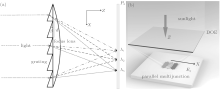
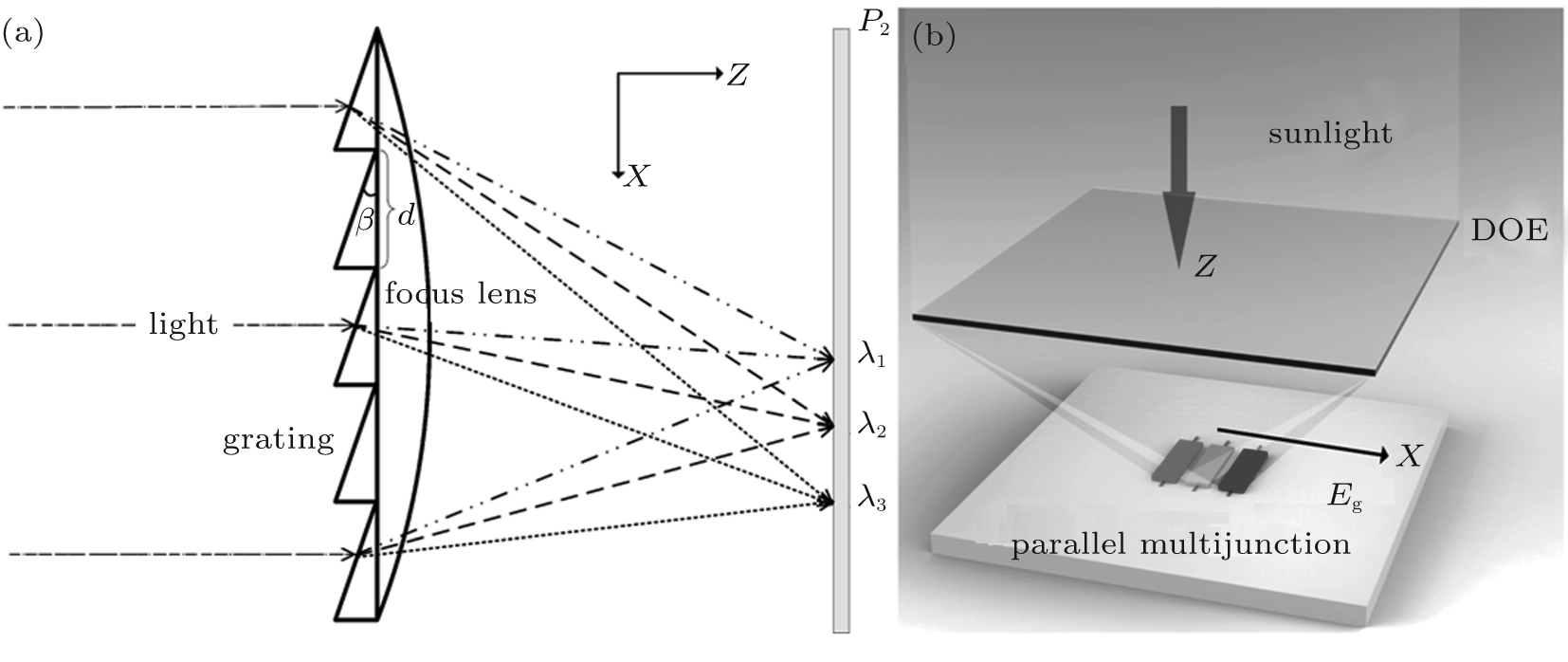
The DOE is a kind of optical element which can realize various optical functions such as dispersion, concentration, and beam reshaping by designing its surface-relief structure. The design and fabrication of DOE have been extensively developed in the last 40 years.[24– 30] In this paper, the DOE with the functions of spectrum splitting and concentrating is concerned for photovoltaic application. As is well known, the diffraction grating and the focus lens can be used to split the spectrum and concentrate the light, respectively. To split the waves efficiently, the diffraction grating should be designed as blazed grating with which most energy is located in the nonzero-order diffraction. Figure 1(a) presents the scheme of the design which consists of a special blazed grating and a thin focus lens. In our previous work, [23] a thickness distribution of the DOE has been proposed as follows:
where x1m is the size of the DOE in the X direction, x1 is the coordinate which ranges from – x1m/2 to x1m/2 with x1 = 0 at the center of the DOE, n is the refractive index of the DOE whose dispersive effect is ignored[31] (Supplementary information, [32] Figs. S1 and S2), f is the focal length of the lens, λ 0 is chosen as the average wavelength considering the wavelength range, β is the angle of the refractive blazed grating, and d is the grating constant which is chosen to be λ 0cot(β )/(n – 1) so that most energy of wavelength λ 0 is diffracted into its first-order diffraction, as shown in Fig. 1(a). The mod(a, b) is the modulus function and its value lies between 0 and b for any positive real numbers a and b.
Fig. 1. (a) Scheme of special DOE which implements spectrum spliting and concentrating functions in the X direction. The Y direction is perpendicular to the paper and sunlight is shed along the Z direction. (b) Scheme of the parallel multijunction solar cells architecture with a DOE to split and concentrate sunlight in the X direction, and concentrate sunlight in the Y direction. Solar cells with increasing band gaps (Eg) are laterally placed along the X direction in sequence according to the spectrum distribution on the output plane (P2).
To facilitate the fabrication of the prototype of the DOE in our lab, we have proposed a thickness optimization algorithm to attenuate hx(x1) to a reasonable value[22, 23, 33] while still maintaining the functions of spectrum-splitting and concentrating (Fig. S1 in Supporting information). To increase the concentration, a thin focus lens is designed in the Y direction as
where y1m and y1 have similar meaning with x1m and x1, respectively. Consequently, the thickness distribution of the DOE can be written as
and the field distribution U1(x1, y1, λ ) on the input plane P1 is expressed as
where k = 2π /λ is the wave vector and ρ 1(x1, y1, λ ) is the amplitude of the input light of wavelength λ . The intensity | ρ 1(x1, y1, λ )| 2 can be energy flux or photon flux. If we consider normal incidence of sunlight with a uniform distribution on P1, ρ 1(x1, y1, λ ) is simplified as ρ 1(λ ). The field distribution U2(x2, y2, λ ) on the output plane (P2) can be calculated by the following equation:[34]
where G(x1, y1; x2, y2; f, λ ) is the well-known transform kernel of light travelling in free space. In the Fresnel diffraction system where paraxial approximation is applied, it has the form[24]
The intensity I2 (x2, y2, λ ) = | U2 (x2, y2, λ )| 2 is calculated accordingly and an analytical expression is obtained as
where N is the grating period, and
Since the factors in the Y direction perform energy redistribution only in the Y direction, the line intensity is defined as
where I0X = d2(ρ (λ ))2/(λ f). In this paper, a rectangular region is written as [a, b] × [c, d], which means that for the region, x is between a and b, and y is between c and d. equals to ∫ regionI2 (x2, y2, λ )dx2 dy2 in the region [x2a, x2b] × [− ∞ , ∞ ] onP2. To evaluate the performance of the DOE, the optical efficiency η light(λ ) is defined as
By solving Eq. (9), the focal positions of the waves are found. Here, the DOE is designed to diffract most energy of wavelength λ to the first-order diffraction, thus the focal position xfoc (λ ) is obtained based on the grating equation
In our design, the following parameters are used: f = 60.0 cm, β = π /20 rad, λ 0 = 525 nm, n = 1.46, x1m = Nd = 2.000 cm, y1m = 4.000 cm.
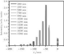
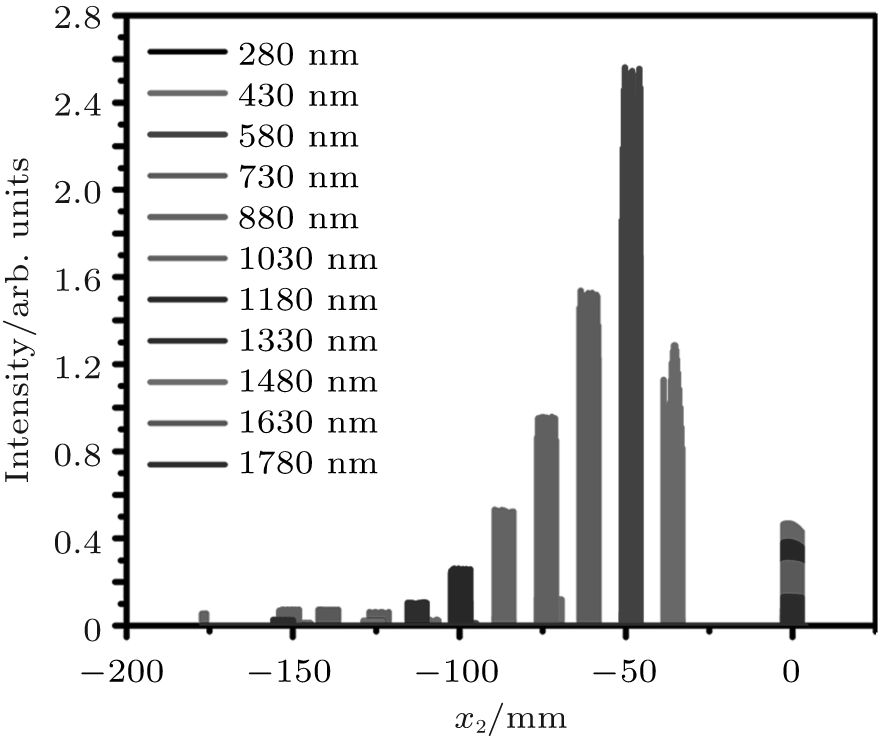
Figure 2 presents the light intensity distribution on P2 after the modulation of the DOE. It should be noted that the sunlight divergence angle of 2 × 0.266° has been considered, and a bigger β compared to our previous work[23] is chosen to counteract the divergence of the sunlight in this paper. It is obvious that different waves are well split and concentrated at different positions according to their wavelengths on P2 (Eq. (11)). The first rainbow region is defined as the region where x2 ∈ [xfoc(λ max), xfoc(λ min)] (λ min = 280 nm, λ max = 1930 nm). Besides, many waves lie in the region x2 ∼ 0, which is defined as the zero-order diffraction region. The parallel multijunction solar cells (Fig. 1(b)) discussed in the following sections will be designed based on the characteristics of the light intensity distribution here. The reflective losses have not been counted in yet and will be discussed in Supplementary information. Normal incidence of sunlight is considered because tracking systems are often employed in concentrated photovoltaic and multijunction solar cells.
Fig. 2. Light intensity distribution on P2 considering the divergence angle of sunlight (2 × 0.266° ).
3. Limiting efficiency of parallel multijunction solar cells based on highly efficient spectrum-splitting and -concentrating DOE
For solar cells with band gap Eg = hc/λ g, where h is the Planck constant, c is the speed of light in the vacuum, and λ g is the wavelength corresponding to the band gap, it is well known that the solar cells can only convert light with wavelengths λ < λ g. In order to achieve full-spectrum absorption, solar cells with different band gaps should be used to convert the corresponding parts of the sunlight. In this special case that the sunlight is manipulated by the DOE, a first rainbow region and a zero-order diffraction region are formed in the X direction, as presented in Fig. 2. In addition, as the formula implies, almost all the energy in the region of [x2a, x2b] × [− ∞ , ∞ ] is actually concentrated in the region of [x2a, x2b] × [− y2m/2, y2m/2]. Consequently, if we use M solar cells with increasing band gaps Eg(i) = hc/λ g(i) (i = 1, 2, 3, … , M) to convert the sunlight, cell i should be placed in the first rainbow region [xfoc(λ g(i)), xfoc(λ g(i + 1))] × [− y2m/2, y2m/2]. Moreover, in order to make full use of the energy on P2 without adding new solar cells, the solar cell with the smallest Eg, i.e. Eg(1), should also be placed in the zero-order diffraction region where most infrared light is concentrated (Fig. 2(b)).
Given the radiation flux Is(λ ) and band gap Eg, the limiting efficiency of the solar cell can be calculated (Detailed equations and discussion can be found in Supplementary Information). To calculate the limiting efficiency of such a photovoltaic system, the parameters in the equations should be changed as follows. The parameter (ρ 1(λ ))2 in Eqs. (4)– (10) should be replaced with the actual sunlight (AM1.5G) photon flux. And for a given region [x2a, x2b] × [− y2m/2, y2m/2] on P2 where the solar cell with band gap Eg is placed, Is(λ ) is given by
Using Eq. (12), we obtain the power output P(Eg) and efficiency η (Eg) of the solar cell. The photovoltaic conversion efficiency of the whole system is defined as
4. Results
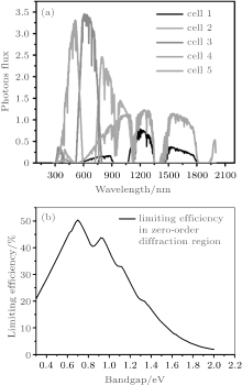
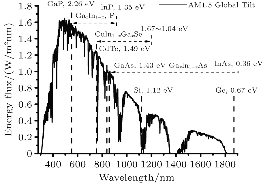
To verify the feasibility of this kind of parallel multijunction solar cells, M = 3– 5 junctions solar cells are used to absorb the sunlight on P2, and the optimum band gaps are 0.93 eV, 1.40 eV, 2.05 eV; 0.70 eV, 1.13 eV, 1.64 eV, 2.23 eV; and 0.69 eV, 0.98 eV, 1.38 eV, 1.81 eV, 2.40 eV, [36] respectively. III– V, Si, CdTe, and CuInGaSe solar cells with appropriate band gaps and highest IPCEs near these band gaps can be chosen from Fig. 3 and solar cell efficiency tables.[1] These solar cells can be fabricated separately and placed laterally (Fig. 1(b)). In order to give a typical value of the possible photovoltaic efficiency of the parallel multijunction solar cells based on such kind of DOE, we use the output pattern of the special DOE (Fig. 2). Detailed configurations and results are listed in Table 1. Solar cells with Eg = 0.7 eV are placed in two regions in their group. The last column is the total photovoltaic conversion efficiency η total (Eq. (13)) of the parallel multijunction solar cells. As can be seen from Table 1, a total efficiency up to 49.15% is expected based on this kind of parallel 4-junction solar cells. Additionally, the efficiency of each cell η (Eg) is high because the losses due to thermalization and lack of absorption, which play an important role in single junction solar cell, [7] are reduced dramatically. This result may be contributed to the fact that the sunlight is well split and concentrated by the designed DOE (Fig. 2(a)), and consequently enable the solar cells to absorb the corresponding parts of the spectrum, as shown in Fig. 4(a). It should be noted that the spectrum in each cell has overlapped spectral regions (Fig. 4(a)), because the sunlight divergence counteracts the splitting effect. Following the same procedure, we calculate the limiting efficiencies of parallel multijunction solar cells composed of solar cells with energy gaps of 0.93 eV, 1.40 eV, 2.05 eV; 0.70 eV, 1.13 eV, 1.64 eV, 2.23 eV; and 0.69 eV, 0.98 eV, 1.38 eV, 1.81 eV, 2.40 eV, and obtain total efficiencies of 46.91%, 48.03, and 50.53%, respectively. The previous works have shown that more junctions will lead to a higher efficiency.[4, 37, 38] As a result, six or more junctions may be an attractive and feasible way to further improve the theoretical efficiency to 50% without technical difficulties in tandem multijunction solar cells under this design due to the rainbow pattern on P2.
Fig. 4. (a) Photon flux spectrum on each solar cell on P2 of 4-junction solar cells. (b) Limiting efficiency versus band gap for radiation in zero-order diffraction region.
Table 1.
Table 1.
Table 1. Configurations and results of parallel 4-junction solar cells.
Cell
Eg/eV
Region/mm
η (Eg)/%
η total /%
1
[– 155.20, − 93.41] × [– 2.936, 2.936]
32.52
5
0.70
[– 3.1, 3.1] × [– 2.936, 2.936]
39.25
2
1.12
[– 93.41, − 63.38] × [– 2.936, 2.936]
52.28
49.15
3
1.64
[– 63.38, − 46.50] × [– 2.936, 2.936]
62.68
4
2.23
[– 46.50, − 20.50] × [– 2.936, 2.936]
64.92
Table 1. Configurations and results of parallel 4-junction solar cells.
5. Discussion
In our present work, the design of the DOE and the option of the solar cells have not been optimized yet in the following aspects. Firstly, the size of this special DOE is 20.0 mm × 40.0 mm, with a total maximum thickness of 910.0 μ m, which can be optimized and attenuated to facilitate the fabrications and applications. For instance, if y1m is too big, the focal lens in the Y direction can be manufactured at the other side of the DOE separately to reduce the difficulty in fabrication, and h1(x1) can be attenuated with thickness optimization algorithms[23, 33] (see supporting information for discussion of controlling the thickness optimization by applying the thickness optimization algorithms). Besides, according to the basic knowledge of phase modulation, we can use a reflective DOE structure to replace the aforementioned refractive DOE. With the same modulation thickness (Δ h) of the surface-relief structure, the reflective structure has the phase modulation Δ ϕ = 2π nF × 2Δ h/λ , much better in modulating the phase than refractive DOE whose Δ ϕ = 2π (n(λ ) − 1)Δ h/λ , that is about 2nF/(n(λ )– 1) times better in phase modulation. Here nF is the refractive index of the materials filled in the surface-relief structure of the reflective DOE to enhance the ability of phase modulation. Even for nF = 1 (air), a reflective DOE with the etching depth of 209.3 μ m (given by 910 μ m/(2nF/(n(λ 0)– 1))) would have the same optical functions of the 910 μ m refractive DOE. The obtained analytical expressions make optimization and analysis a much easier task. Secondly, the choice of solar cells is based on the assumption that the spectrum is ideally split, for instance, light with wavelengths 280– 557 nm is total absorbed by the solar cell with Eg = 2.23 eV and 557– 757 nm is totally absorbed by the solar cell with Eg = 1.64 eV, etc.[36] The previous works have shown that the optimum combination of band gaps is closely related to the intensity distribution.[4, 37– 39] Given that the spectrum on cell 5 is widely spread from 300 nm to 1800 nm, while the spectrum on cell 1 is from 1200 nm to 1800 nm (Fig. 4(a)), at least two proper cells can be found for these two regions other than the current one. Figure 4(b) shows that the solar cell with Eg = 0.7 eV is most efficient in absorbing light in the zero-order diffraction region. The 4-junction solar cells, which contain solar cells with band gaps of 0.7 eV and 1.13 eV (CuInGaSe or Si solar cell), may be an attractive option to achieve higher efficiency with less junctions and lower cost. In one word, co-design of the DOE and the solar cells is still needed to optimize the system and realize cost-effective and practical design of high efficiency solar cells. Lastly, the calculation is based on 100% incident photon-to-electron conversion efficiency (IPCE) of the solar cells, a 85%– 90% discount of the total efficiency should be estimated according to the actual IPCEs in the interested spectral regions.[1, 41] With more junctions and optimization of the DOE, an experimental photovoltaic efficiency over 40% can be achieved.
Nevertheless, compared to the tandem solar cells, the parallel multijunction solar cells proposed here have several advantages. Firstly, most harmful infrared light[16] is directed away from the cells in the rainbow region and utilized by narrow-band-gap solar cells, therefore the heat load is reduced and a higher concentration can be applied. Secondly, all the cells can be fabricated separately, thus the requirement of epitaxial growth technology is not necessarily needed while tandem multijunction solar cells still can be integrated in this design and would surely increase the final efficiency. Thirdly, more cells can be integrated in this parallel multijunction solar cells system, indicating even higher efficiency may be achieved, while only 2-junction and 3-junction are preferred in tandem solar cells due to the technical restraints.[8] Specifically, solar cells with wide band gap (Eg > 2.2 eV) or narrow band gap ( Eg < 0.9 eV), as well as solar cells with a good IPCE in a narrow spectral region, which were ignored previously due to their lack of absorption of the wide spectrum of sunlight, can be used in this design to absorb a proper part of the spectrum, especially in five or more junctions solar cells. [36, 42, 43] Lastly, the design parameters can be adjusted and optimized according to different conditions, so it can provide a flexible way for realization. Direct write technology is often used to fabricate the prototype of DOE. Since the DOE is a surface-relief structure on the substrate, once a hard mold with a complementary structure is manufactured, mass production of the DOEs can be realized by replication technology.[27, 43]
6. Conclusion
A special design of highly efficiency spectrum-splitting and -concentrating DOE is described, and the analytical expression of the output intensity distribution is obtained, which facilitates the investigation of the parallel multijunction solar cells based on such kind of DOE. A rainbow pattern and a zero-order diffraction region are generated by the DOE. An appropriate solar cell placed in the zero-order diffraction region is important in achieving high photovoltaic efficiencies. Existing solar cells, such as III– V, Si, CdTe, and other new-types of solar cells can be chosen to absorb the modulated sunlight without adding technical difficulties. A limiting efficiency over 40% of such a photovoltaic system can be achieved under AM1.5G radiation based on Shockley– Queisser’ s theory. The results would definitely provide an important alternative to implement cost-effective and practical design of high efficiency solar cells by using the existing solar cells effectively. Further work of economic evaluation and systematic optimizations of the photovoltaic system are needed to achieve cost-effective and high-efficiency multijunction solar cells.
GreenM A and Ho-BaillieA2010Prog. Photovolt. Res. Appl. 1842DOI:10.1002/pip.v18:1[Cited within:1]
6
KingR, SherifR, KinseyG, KurtzS, FetzerC, EdmondsonK, LawD, CotalH, KrutD, ErmerJ and KaramN H2005International Conference on Solar Concentrators for the Generation of Electricity or Hydrogen3040[Cited within:1]
7
PolmanA and AtwaterH A2012Nat. Mater. 11174DOI:10.1038/nmat3263[Cited within:1][JCR: 35.749]
LudmanJ E, RiccobonoJ, SemenovaI V, Reinhand N O, TaiW, LiX, SyphersG, RallisE, SlikerG and MartínJ1997Solar Energy601DOI:10.1016/S0038-092X(96)00148-X[Cited within:1][JCR: 2.475][CJCR: 0.2262]
GuB Y, YangG Z, DongB Z, ChangM P and ErsoyO K1995Appl. Opt. 342564DOI:10.1364/AO.34.002564[Cited within:1][JCR: 1.689]
29
HerbjønrødA, Schjøberg-HenriksenK, AngelskårH and LacolleM2009Journal of Micromechanics and Microengineering19125022DOI:10.1088/0960-1317/19/12/125022[Cited within:1][JCR: 1.79]
WangJ Z, YeJ S, HuangQ L, XuX, LiD M, MengQ B and YanG Z2014Chin. Phys. B23044211DOI:10.1088/1674-1056/23/4/044211[Cited within:2][JCR: 1.148][CJCR: 1.2429]
KimS MKimD MKangSAhnS2003Micromachining Technology for Micro-Optics and Nano-Optics63DOI:10.1117/12.472903[Cited within:2]
4
2013
0.0
0.0
... 8%)[1] of single-junction solar cells is very close to the maximum theoretical efficiency of 33% decided by the Shockley#cod#x2013 ...
... [1,8] To overcome the shortcomings of the tandem multijunction solar cells, parallel multijunction solar cells have been proposed ...
... [1] These solar cells can be fabricated separately and placed laterally (Fig ...
... [1,41] With more junctions and optimization of the DOE, an experimental photovoltaic efficiency over 40% can be achieved ...
1
1961
0.71
0.0
... Queisser limit,[2] and efficiencies of emerging third generation solar cells such as hot carrier, intermediate band, up/down conversion, and quantum dot solar cells are still low ...
1
2005
0.0
0.0
... [3] Further developing high-efficiency and cost-effective solar cells is of vital importance to the large-scale photovoltaic application ...
3
2007
5.024
0.0
... [4#cod#x2013 ...
... [4,37,38] As a result, six or more junctions may be an attractive and feasible way to further improve the theoretical efficiency to 50% without technical difficulties in tandem multijunction solar cells under this design due to the rainbow pattern on P2 ...
... [4,37#cod#x2013 ...
1
2010
0.0
0.0
1
2005
0.0
0.0
1
2012
35.749
0.0
... (Eg) is high because the losses due to thermalization and lack of absorption, which play an important role in single junction solar cell,[7] are reduced dramatically ...
3
2009
1.844
0.0
... [8,10,11] As a result, current tandem multijunction solar cells are 2-junction and 3-junction with limited combinations, such as InGaP/GaAs/InGaAs, GaInP/GaAs/GaInNAs, GaInP/ GaInAs/Ge, AlInGaP/GaAs/Ge, and GaInP/GaAs ...
... [1,8] To overcome the shortcomings of the tandem multijunction solar cells, parallel multijunction solar cells have been proposed ...
... [8] Specifically, solar cells with wide band gap (Eg > 2 ...
1
2011
0.71
0.0
... 9] However, solar cells with efficiencies greater than 40% are dominated by series-connected tandem multijunction solar cells under high concentration, which have to meet current matching and lattice matching simultaneously and be fabricated with complex and expensive epitaxial growth technology ...
1
2000
4.078
0.0
... [8,10,11] As a result, current tandem multijunction solar cells are 2-junction and 3-junction with limited combinations, such as InGaP/GaAs/InGaAs, GaInP/GaAs/GaInNAs, GaInP/ GaInAs/Ge, AlInGaP/GaAs/Ge, and GaInP/GaAs ...
1
2004
1.552
0.0
... [8,10,11] As a result, current tandem multijunction solar cells are 2-junction and 3-junction with limited combinations, such as InGaP/GaAs/InGaAs, GaInP/GaAs/GaInNAs, GaInP/ GaInAs/Ge, AlInGaP/GaAs/Ge, and GaInP/GaAs ...
2
2010
0.0
0.0
... In this kind of solar cells, the sunlight is split into different spectral bands by dispersive optical elements[12,13] such as the dichroic mirror,[14] and absorbed by the corresponding solar cells ...
... [12] Besides, concentration is needed to offset the high cost and increase the efficiency ...
1
2010
1.844
0.0
... In this kind of solar cells, the sunlight is split into different spectral bands by dispersive optical elements[12,13] such as the dichroic mirror,[14] and absorbed by the corresponding solar cells ...
1
2008
0.0
0.0
... In this kind of solar cells, the sunlight is split into different spectral bands by dispersive optical elements[12,13] such as the dichroic mirror,[14] and absorbed by the corresponding solar cells ...
1
1979
0.0
0.0
... [15] Holographic systems, which can split and concentrate the sunlight by volume phase modulation of the wave front, have also been proposed by researchers ...
3
2004
0.0
0.0
... [16#cod#x2013 ...
... [16#cod#x2013 ...
... Firstly, most harmful infrared light[16] is directed away from the cells in the rainbow region and utilized by narrow-band-gap solar cells, therefore the heat load is reduced and a higher concentration can be applied ...
1
1997
2.475
0.2262
1
1982
1.689
0.0
1
1982
0.782
0.0
... 19] The holographic optical element is implemented by recording the interference field of laser beams ...
2
2012
3.546
0.0
... 20] Recently, a single prismatic structure, which splits and concentrates light based on the dispersive behavior of the employed material, has been designed and fabricated, and its optical properties were discussed ...
... [20] A structure composed of a blazed grating and a cylindrical lens designed for the space was also proposed ...
1
2013
0.0
0.0
... [21] A single thin planar diffractive optical element (DOE), which can implement the function of sunlight splitting and concentrating in one direction synthetically by designing its surface-relief structure, was proposed in our recent work ...
2
2013
1.689
0.0
... [22,23] The optical efficiency of the DOE under visible light was also discussed ...
... To facilitate the fabrication of the prototype of the DOE in our lab, we have proposed a thickness optimization algorithm to attenuate hx(x1) to a reasonable value[22,23,33] while still maintaining the functions of spectrum-splitting and concentrating (Fig ...
5
2013
1.148
1.2429
... [22,23] The optical efficiency of the DOE under visible light was also discussed ...
... In our previous work,[23] a thickness distribution of the DOE has been proposed as follows: ...
... To facilitate the fabrication of the prototype of the DOE in our lab, we have proposed a thickness optimization algorithm to attenuate hx(x1) to a reasonable value[22,23,33] while still maintaining the functions of spectrum-splitting and concentrating (Fig ...
... compared to our previous work[23] is chosen to counteract the divergence of the sunlight in this paper ...
... For instance, if y1m is too big, the focal lens in the Y direction can be manufactured at the other side of the DOE separately to reduce the difficulty in fabrication, and h1(x1) can be attenuated with thickness optimization algorithms[23,33] (see supporting information for discussion of controlling the thickness optimization by applying the thickness optimization algorithms) ...
2
1998
0.0
0.0
... [24#cod#x2013 ...
... In the Fresnel diffraction system where paraxial approximation is applied, it has the form[24] ...
1
1972
0.524
0.0
1
1993
1.689
0.0
1
1997
1.224
0.0
... [27,43] ...
1
1995
1.689
0.0
1
2009
1.79
0.0
1
1990
0.0
0.0
... 30] In this paper, the DOE with the functions of spectrum splitting and concentrating is concerned for photovoltaic application ...
1
1965
2.21
0.0
... 0 at the center of the DOE, n is the refractive index of the DOE whose dispersive effect is ignored[31] (Supplementary information,[32] Figs ...
1
0.0
0.0
... 0 at the center of the DOE, n is the refractive index of the DOE whose dispersive effect is ignored[31] (Supplementary information,[32] Figs ...
2
2014
1.148
1.2429
... To facilitate the fabrication of the prototype of the DOE in our lab, we have proposed a thickness optimization algorithm to attenuate hx(x1) to a reasonable value[22,23,33] while still maintaining the functions of spectrum-splitting and concentrating (Fig ...
... For instance, if y1m is too big, the focal lens in the Y direction can be manufactured at the other side of the DOE separately to reduce the difficulty in fabrication, and h1(x1) can be attenuated with thickness optimization algorithms[23,33] (see supporting information for discussion of controlling the thickness optimization by applying the thickness optimization algorithms) ...
1
1986
1.689
0.0
... ) on the output plane (P2) can be calculated by the following equation:[34] ...
1
2008
0.0
0.0
3
2008
0.0
0.0
... 40 eV,[36] respectively ...
... [36] The previous works have shown that the optimum combination of band gaps is closely related to the intensity distribution ...
... 2 eV) or narrow band gap (Eg [36,42,43] Lastly, the design parameters can be adjusted and optimized according to different conditions, so it can provide a flexible way for realization ...
2
1980
0.71
0.0
... [4,37,38] As a result, six or more junctions may be an attractive and feasible way to further improve the theoretical efficiency to 50% without technical difficulties in tandem multijunction solar cells under this design due to the rainbow pattern on P2 ...
... [4,37#cod#x2013 ...
1
1996
0.0
0.0
... [4,37,38] As a result, six or more junctions may be an attractive and feasible way to further improve the theoretical efficiency to 50% without technical difficulties in tandem multijunction solar cells under this design due to the rainbow pattern on P2 ...
1
2008
0.0
0.0
... 39] Given that the spectrum on cell 5 is widely spread from 300 nm to 1800 nm, while the spectrum on cell 1 is from 1200 nm to 1800 nm (Fig ...
1
2012
0.0
0.0
1
2011
3.794
0.0
... [1,41] With more junctions and optimization of the DOE, an experimental photovoltaic efficiency over 40% can be achieved ...
1
2010
0.0
0.0
... 2 eV) or narrow band gap (Eg [36,42,43] Lastly, the design parameters can be adjusted and optimized according to different conditions, so it can provide a flexible way for realization ...
2
2003
0.0
0.0
... 2 eV) or narrow band gap (Eg [36,42,43] Lastly, the design parameters can be adjusted and optimized according to different conditions, so it can provide a flexible way for realization ...
... [27,43] ...
Realizing high photovoltaic efficiency with parallel multijunction solar cells based on spectrum-splitting and -concentrating diffractive optical element*
[Wang Jin-Zea),b),c), Huang Qing-Lia),b),c), Xu Xina),b),c), Quan Bao-Ganga),d), Luo Jian-Henga),b),c), Zhang Yane), Ye Jia-Shenge), Li Dong-Meia),b),c), Meng Qing-Boa),b),c)†, Yang Guo-Zhena),f)‡]


 , Yang Guo-Zhen