
Piezoelectricity in K1− xNa xNbO3: First-principles calculation*
[Li Qiang, Zhang Rui† , Lv Tian-Quan‡, Zheng Li-Mei]
, Lv Tian-Quan‡, Zheng Li-Mei]
|
|


†Corresponding author. E-mail: ruizhang ccmst@hit.edu.cn
‡Corresponding author. E-mail: ltq@hit.edu.cn
*Project supported by the National Basic Research Program of China (Grant No. 2013CB632900).
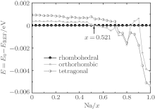
The piezoelectric properties of K1− xNa xNbO3 are studied by using first-principles calculations within virtual crystal approximation. To understand the critical factors for the high piezoelectric response in K1− xNa xNbO3, the total energy, piezoelectric coefficient, elastic property, density of state, Born effective charge, and energy barrier on polarization rotation paths are systematically investigated. The morphotropic phase boundary in K1− xNa xNbO3 is predicted to occur at x = 0.521, which is in good agreement with the available experimental data. At the morphotropic phase boundary, the longitudinal piezoelectric coefficient d33 of orthorhombic K0.5Na0.5NbO3 reaches a maximum value. The rotated maximum of
Lead-based piezoelectric materials have been widely used in sensors, actuators, and accelerometers.[1] However, due to Pb’ s toxicity, there is an increasing attention in the development of high-performance lead-free piezoelectric materials. Environmentally friendly (K, Na)NbO3 (KNN) and its solid solutions show the superior piezoelectric properties at a K/Na ratio of around 50/50, and are the potential substitutes for lead-based piezoelectrics.[2– 7] It is well known that the piezoelectric response is enhanced for piezoelectrics at the morphotropic phase boundary (MPB).[1, 8] Therefore, a great deal of experimental effort has been devoted to search the MPB composition in the K1− xNaxNbO3 system. Studies[9– 12] on the phase transition process in the KNN system suggested that an MPB lies near the composition with 50 mol.% NaNbO3. In those studies, the Na content intervals are too large to verify the accurate K/Na ratio at the MPB. The small intervals in K1− xNaxNbO3 ceramics have been derived by Dai et al.[13] Their results suggested that a typical morphotropic phase boundary exists at x = 0.52– 0.525. Although the accurate MPB in K1− xNaxNbO3 has been confirmed experimentally, some fundamental problems still need to be solved, such as the dominant factor for the high piezoelectric response in K1− xNaxNbO3, the effect of K– O (or Na– O) and Nb– O bonding on the piezoelectric performance, and the effect of Na substitution on the polarization rotation. First-principles calculations can predict various properties well, [14– 18] such as the phase transition and thermodynamic properties, which have been adopted for the purpose of this report.
In this paper, we use first-principles density functional theory within the virtual crystal approximation to predict the MPB in K1− xNaxNbO3 and evaluate its piezoelectric response behaviors. Moreover, the mechanism of a high piezoelectric response and the effect of the domain-engineering method on polarization rotation in K1− xNaxNbO3 near the MPB are also investigated. To the best of our best knowledge, it is the first time that the MPB of KNN has been obtained theoretically. This paper is organized as follows. Theoretical methods are described in Section 2. The results for the structural parameter, bulk modulus, band gap, Born dynamical charge, and piezoelectric property are discussed in Section 3. Finally, the conclusions are given in Section 4.
The first-principles calculations are conducted using the density functional theory (DFT) and plane wave pseudopotential method implemented in the ABINIT software package.[19– 22] In order to quantitatively investigate the MPB and related phenomena, the virtual crystal approximation (VCA)[23] is adopted because it has been successfully applied to some perovskite solutions (e.g., PZT, [24, 25] NBT-BT, [26] PSN, [27] and LNTO[28]). The exchange correlation potential is described by the local-density approximation within the Hartwigsen– Goedecker– Hutter (HGH) pseudopotentials.[29] We treat 9 valence electrons for K (3s23p64s1) and Na (2s22p63s1), 6 for O (2s22p4), and 13 for Nb (4s24p64d45s1). The Brillouin zone (BZ) is sampled by a 5 × 5 × 5 Monkhorst– Pack mesh of k points for cubic, rhombohedra, orthorhombic, and tetragonal K1− xNaxNbO3. To achieve high accuracy in the total energy calculation and ionic relaxation, we use a very high plane-wave energy cutoff of 3591 eV, and the convergence for the maximum tolerance on the wave function squared residual is set to 10− 18. Firstly, the appropriate cell parameters of K1− xNaxNbO3 are obtained after optimizing the lattice constants and internal atom coordinates based on the maximal force tolerance (0.0257 eV/Å ). Secondly, the total energy, piezoelectric constant, Born effective charge, and elastic property calculations for K1− xNaxNbO3 are performed by the density functional perturbation theory (DFPT).[30]
Above the Curie temperature (around 624 K), KNbO3 (KNO) is a typical perovskite structure with the cubic symmetry. Cooling KNO from the Curie temperature leads to a continuous phase transition in a cubic-tetragonal-orthorhombic-rhombohedral sequence. The calculated lattice parameter, bulk modulus, and band gap for these phases are presented in Table 1. The lattice constant a and the cell volume V of the cubic phase are calculated to be 3.968 Å and 62.46 Å 3, respectively, which are in good agreement with the experimental values (4.021 Å and 65.01 Å 3).[32] The calculated c/a ratio for the tetragonal KNO is 1.034, which agrees with the available experimental result (1.017).[36] According to the present DFT calculations, the unit-cell parameters of a = 5.629 Å , b = 3.959 Å , and c = 5.633 Å are predicted for the orthorhombic KNO. The rhombohedral KNO with the space group R3m only exists below room temperature.
| Table 1. Lattice parameter, volume, bulk modulus, band gap, and piezoelectric constant of the cubic, tetragonal, orthorhombic, and rhombohedral KNbO3, compared with experimental and theoretical data. For each phase, the error of lattice parameter with respect to the experimental data is given. |
Compared with the reported experimental data, [32, 36, 37] our calculated cell parameters listed in Table 1 have an accuracy with a relative error of ± 1.6%. The predicted bulk modulus for the cubic and orthorhombic KNO are 132 GPa and 185 GPa, respectively, which are consistent with the experimental data (138 GPa and 172 GPa).[34, 38] The calculated piezoelectric coefficients d33 are also in reasonable agreement with the experimental and theoretical data.[33, 39]
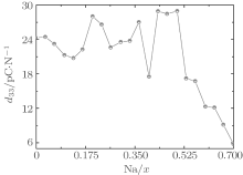
At the MPB, the piezoelectric materials would show the high piezoelectric properties. In order to further verify our prediction, we calculate the piezoelectric coefficients (d33 and d15). Figure 2 only shows d33 of the orthorhombic K1− xNaxNbO3 in the range of x = 0.0– 0.7, because the elastic constant calculations suggest that the orthorhombic K1− xNaxNbO3 becomes mechanically instable in the range of x > 0.7. The d33 of the orthorhombic structure shows a maximum value at x = 0.5. This result is in agreement with the experimental measurements.[9– 12] The reason for the peak value at x = 0.2 is unclear yet. There may be another MPB or phase boundary. Similarly, the d33 also shows a maximum at x = 0.2 in both BiFe1− xCoxO and (NBT)1− x-(K1/2BiTiO3)x, which has been thoroughly verified by the experimental[41– 43] and theoretical[44] studies.
 | Fig. 2. d33 of the orthorhombic K1− xNaxNbO3 as a function of x. |
The shear piezoelectric coefficient d15 is also very important for piezoelectrics. Therefore, we calculate d15 as a function of x for the orthorhombic K1− xNaxNbO3. As shown in Fig. 3, there are three peaks located at x = 0.2, 0.464, and 0.7. Although d15 at x = 0.7 is the highest among the three peaks, the corresponding d33 is the lowest. At x = 0.464, d15 is calculated to be 153.52 pC/N, which further identifies the MPB in K1− xNaxNbO3.
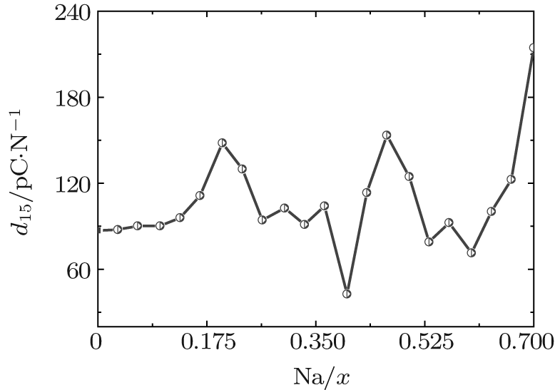 | Fig. 3. d15 of the orthorhombic K1− xNaxNbO3 as a function of x. |
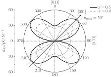
According to the suggestion of Davis et al., [45] the largest longitudinal piezoelectric response would be found away from the polar direction when the ratio d15/d33 is larger than 1.5, and the crystals can be categorized into “ rotator” ferroelectrics with d15/d33 > 1.5 and “ extender” with d15/d33 < 1.5. According to the predicted piezoelectric coefficients d33 and d15, the d15/d33 value is 7.29 for the orthorhombic K0.5Na0.5NbO3. Thus, the orthorhombic K0.5Na0.5NbO3 belongs to “ rotator” ferroelectrics and is highly anisotropic. The large anisotropy is also observed in other single-domain relaxor-PT-based crystals near their MPBs.[8] It is necessary for investigating the crystal orientation dependence of the piezoelectric properties. From the calculated single-domain data of the orthorhombic K1− xNaxNbO3 with x = 0.5 and 0.0, the orientation dependence of the intrinsic piezoelectric coefficient 


 | Fig. 4. Orientation dependence of piezoelectric coefficient  |
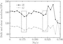
For the orthorhombic K1− xNaxNbO3 with x = 0.5, there are nine independent elastic constants (c11, c22, c33, c44, c55, c66, c12, c13, and c23), which are obtained using DFPT. From the calculated elastic constants, both the bulk modulus (B) and shear modulus (G) can be derived using Voigt– Reuss– Hill (VRH) approximation, [48] and the results are presented in Fig. 5. The VRH bulk modulus is defined as the average B = (BV + BR)/2 between the Voigt upper and Reuss lower bounds


The VRH shear modulus G = (GV + GR)/2 is taken from the average between the Voigt upper GV and Reuss lower GR bounds

From Fig. 5, three minimum value of the bulk B and shear G modulus are located at x = 0.2, 0.464, and 0.7. The bulk B and shear G modulus at x = 0.7 are the smallest among the three minimum values. The corresponding d33 is also the smallest, as shown in Fig. 2. This implies that the small bulk and shear modulus would not necessarily give rise to a high piezoelectric response. Otherwise, the exceptionally high bulk and shear modulus are also not conducive to a high piezoelectric response. Therefore, the moderate bulk and shear modulus are better for the piezoelectric response.
 | Fig. 5. Bulk and shear modulus of the orthorhombic K1− xNaxNbO3 as a function of x. |
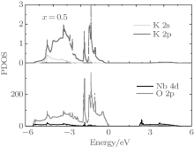
The first-principles studies have suggested that the orbital hybridization between the Pb 6s state and O 2p states plays a crucial role for large ferroelectricity in tetragonal PbTiO3.[49] The prediction is later verified experimentally, [50] i.e., the Pb– O bonds in tetragonal PbTiO3 show rather strong covalency. In order to investigate the interaction between Nb– O and K– O bonds, we plot the partial density of state (PDOS) of the Nb, K, and O orbitals for the orthorhombic K1− xNaxNbO3 with x = 0.5. As shown in Fig. 6, the K 2s and 2p, O 2p orbits are mainly located in the range from − 5.6 to 0 eV, indicating that the K– O bonds are mainly ionic. The calculated Born effective charge of K is 1.13, which is close to its oxidation state, further confirming the characteristic of ionic interaction between K and O ions. The Nb 4d orbits mixed with O 2p orbits are located in the valence band and conduction band, suggesting that the Nb– O bonds are both ionic and covalent. The calculated average Born effective charge of Nb is 8.79, larger than its oxidation state (+ 5), indicating that the Nb– O bonds are not purely ionic. Thus, the high piezoelectric for orthorhombic K1− xNaxNbO3 with x = 0.5 is related to the Nb– O covalency. This agrees with the recent theoretical study.[51]
 | Fig. 6. Partial density of state of the orthorhombic K1− xNaxNbO3. |
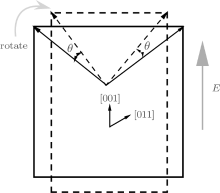
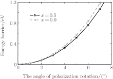
To understand the physical mechanism of the high piezoelectric response for the orthorhombic K1− xNaxNbO3, we calculate the energy barrier on polarization rotation paths along the [001] direction through a simple approach: E(θ ) = E0(θ ) − E0(0), where E(θ ) is the energy barrier with θ being the angle of polarization rotation, E0(θ ) is the total energy of the orthorhombic K1− xNaxNbO3, and E0(0) denotes the total energy with θ = 0° . The adopted model for the energy barrier calculations is illustrated in Fig. 7, and the results are depicted in Fig. 8. As shown in Fig. 8, the energy barrier of the orthorhombic K1− xNaxNbO3 with x = 0.0 and x = 0.5 increases with the increase of the angle θ . However, the energy barrier of the orthorhombic K1− xNaxNbO3 with x = 0.5 increases more slowly than the one with x = 0.0, indicating that at MPB, the phase instability of the orthorhombic K1− xNaxNbO3 with x = 0.5 is enhanced and the polarization rotation becomes easier than the pure KNO, i.e., the flat free energy profile is the most important factor for inducing a high piezoelectric response.
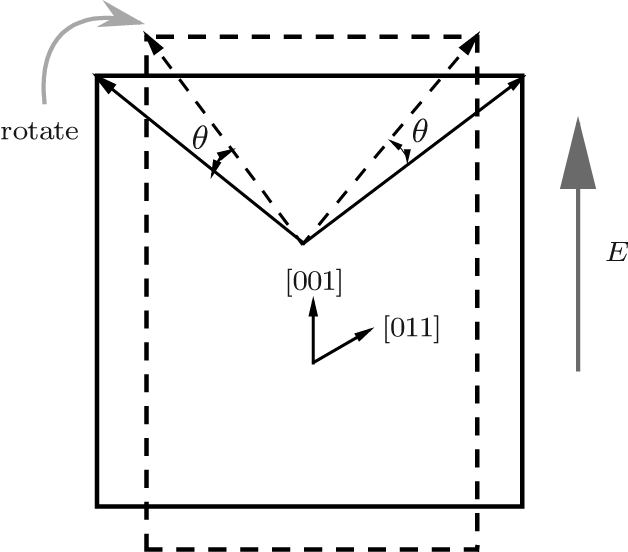 | Fig. 7. Schematic of polarization rotation of the orthorhombic K1− xNaxNbO3 resulting from [001] electric field. |
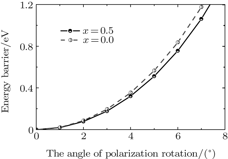 | Fig. 8. Energy barrier of the orthorhombic K1− xNaxNbO3 with x = 0.5 and 0.0 on polarization rotation paths along the [001] direction. |
First-principles density functional theory within the virtual crystal approximation is applied to investigate the morphotropic phase boundary and piezoelectric properties of K1− xNaxNbO3. The structure parameter, bulk modulus, band gap, and piezoelectric coefficients have been calculated. The MPB in K1− xNaxNbO3 is predicted to be located at x = 0.521, which is in good agreement with the experimental data. The dependence of the longitudinal piezoelectric coefficient on the polarization orientation proves that the highest value of the piezoelectric coefficient 
| 1 |
|
| 2 |
|
| 3 |
|
| 4 |
|
| 5 |
|
| 6 |
|
| 7 |
|
| 8 |
|
| 9 |
|
| 10 |
|
| 11 |
|
| 12 |
|
| 13 |
|
| 14 |
|
| 15 |
|
| 16 |
|
| 17 |
|
| 18 |
|
| 19 |
|
| 20 |
|
| 21 |
|
| 22 |
|
| 23 |
|
| 24 |
|
| 25 |
|
| 26 |
|
| 27 |
|
| 28 |
|
| 29 |
|
| 30 |
|
| 31 |
|
| 32 |
|
| 33 |
|
| 34 |
|
| 35 |
|
| 36 |
|
| 37 |
|
| 38 |
|
| 39 |
|
| 40 |
|
| 41 |
|
| 42 |
|
| 43 |
|
| 44 |
|
| 45 |
|
| 46 |
|
| 47 |
|
| 48 |
|
| 49 |
|
| 50 |
|
| 51 |
|