Li Chen, Tan Qiu-Lin, Xue Chen-Yang, Zhang Wen-Dong, Li Yun-Zhi, Xiong Ji-Jun. Wireless contactless pressure measurement of an LC passive pressure sensor with a novel antenna for high-temperature applications* . Chinese Physics B, 2015, 24(4): 048801
Permissions
Wireless contactless pressure measurement of an LC passive pressure sensor with a novel antenna for high-temperature applications*
Li Chena),b), Tan Qiu-Lina),b)†, Xue Chen-Yanga), Zhang Wen-Dongb), Li Yun-Zhib), Xiong Ji-Junb)‡
Science and Technology on Electronic Test and Measurement Laboratory, North University of China, Taiyuan 030051, China
Key Laboratory of Instrumentation Science and Dynamic Measurement, Ministry of Education, North University of China, Taiyuan 030051, China
*Project supported by the National Natural Science Foundation for Distinguished Young Scholars, China (Grant No. 51425505), the National Natural Science Foundation of China (Grant No. 61471324), the Program for the Outstanding Innovative Teams of Higher Learning Institutions of Shanxi Province, China (Grant No. 2013-077), and the Graduate Students Outstanding Innovation Project of Shanxi Province, China (Grant No. 20143020).
Abstract
In this paper, a novel antenna is proposed for high-temperature testing, which can make the high-temperature pressure characteristics of a wireless passive ceramic pressure sensor demonstrated at up to a temperature of 600 °C. The design parameters of the antenna are similar to those of the sensor, which will increase the coupling strength between the sensor and testing antenna. The antenna is fabricated in thick film integrated technology, and the properties of the alumina ceramic and silver ensure the feasibility of the antenna in high-temperature environments. The sensor, coupled with the ceramic antenna, is investigated using a high-temperature pressure testing platform. The experimental measurement results show that the pressure signal in a harsh environment can be detected by the frequency diversity of the sensor.
Although some sensors possess their good performances, most passive sensors are powered, which restricts their working time in actual working environments.[1– 4] One possible solution to this problem is to supply power to the sensor by means of magnetic field radiation, which does not require the sensor to be powered using batteries; this approach can also prevent disasters or failures in the system structure.[5] For the high-temperature environments there is growing demand for measuring pressure parameters, which are still difficult to determine.[6] Recently, some high-temperature pressure sensors based on ceramics have been developed. These ceramic sensors are based on a wireless passive resonant telemetry scheme, which was first proven in 1967 and has been applied to the development of various pressure microsensors.[7– 10] The contactless wireless measurement method can accurately monitor pressure in harsh environments, since it can provide the possibility of the sensor on moving parts, and reduce potential unreliable contacts by the sensor. However, the coupling distance between the antenna and sensor is short, and the sensor may have difficulty in detecting the signal as the working temperature increases. In addition, for pressure tests under high temperatures, the traditional test antenna cannot work in a high-temperature environment, nor can it be coupled effectively with the sensor. These issues make it difficult to determine actual pressure parameters in high-temperature pressure environments. For example, Fonseca et al.[11] and Fonseca[12] developed a wireless passive capacitive high-temperature pressure sensor based on low-temperature co-fired ceramic (LTCC) technology, but it can only work at up to 450 ° C. In 2013, Tan et al., [13] and Xiong et al.[14, 15] designed two sensors based on LTCC and high-temperature co-fired ceramic technologies (HTCC). Unfortunately, owing to the defect in the test antenna, the maximum readout distance between the sensor and the antenna was only 2.8 cm, and the antenna could not work stably in high-temperature environments.
In this paper, a novel design and fabrication method of a ceramic antenna is proposed, which can stably work in high-temperature environments. The same inductance and capacitance as those of the sensor can be integrated in the ceramic substrate for the antenna. A novel fabrication technology is proposed, which includes drilling, cavity filling, stack, isostatic lamination, high-temperature firing, inductance-coil and capacitor– electrode screen printing, and low-temperature sintering. Finally, the fabricated sensor, coupled with the ceramic antenna, can operate at up to 600 ° C for contactless pressure measurement in high-temperature environments.
2. Principle of wireless non-contact measurement
The equivalent circuit of this mutual-inductance coupling system is shown in Fig. 1(a), where L1, C1, and R1 are the inductance, capacitance, and resistance of the antenna, respectively; and L2, C2, and R2 are the inductance, capacitance, and resistance of the sensor, respectively. An inductance and a capacitance, as part of the functional structure of the sensor and antenna, are integrated in the alumina ceramic substrate as shown in Fig. 1(b).
Fig. 1. (a) Wireless passive sensing concept. (b) Elemental structure of ceramic antenna and ceramic sensor.
The antenna and sensor consist of the inductance and capacitance for a series LC resonance circuit. The relationship between current and voltage can be derived by using the theory of the transformer and Kirchhoff’ s law as follows:
where U1 and I1 are the voltage and current, respectively, across the testing coil; I2 is the current across the sensor coil; w is the working frequency; k is the inductive coupling coefficient. Then, the equivalent impedance Zeq of the testing antenna can be presented as
where R1, f, f1, and f2 refer to the resistance, excitation frequency, self-resonance frequency of the antenna, and the self-resonance frequency of the sensor, respectively. In addition,
is the quality factor of the LC resonance circuit. From Eq. (2), when f = f1 = f2, the external reader antenna forms a stronger inductive coupling link with the sensor. The magnitude and phase of the equivalent impedance from the reader antenna can be expressed as follows:
In the above analysis, in order to increase the coupling distance and improve the signal strength, we can make the antenna resonant frequency f1 close to the sensor resonant frequency f2 by integrating the same capacitance plates and inductance coil in the reader antenna and sensor.
3. Fabrication
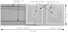
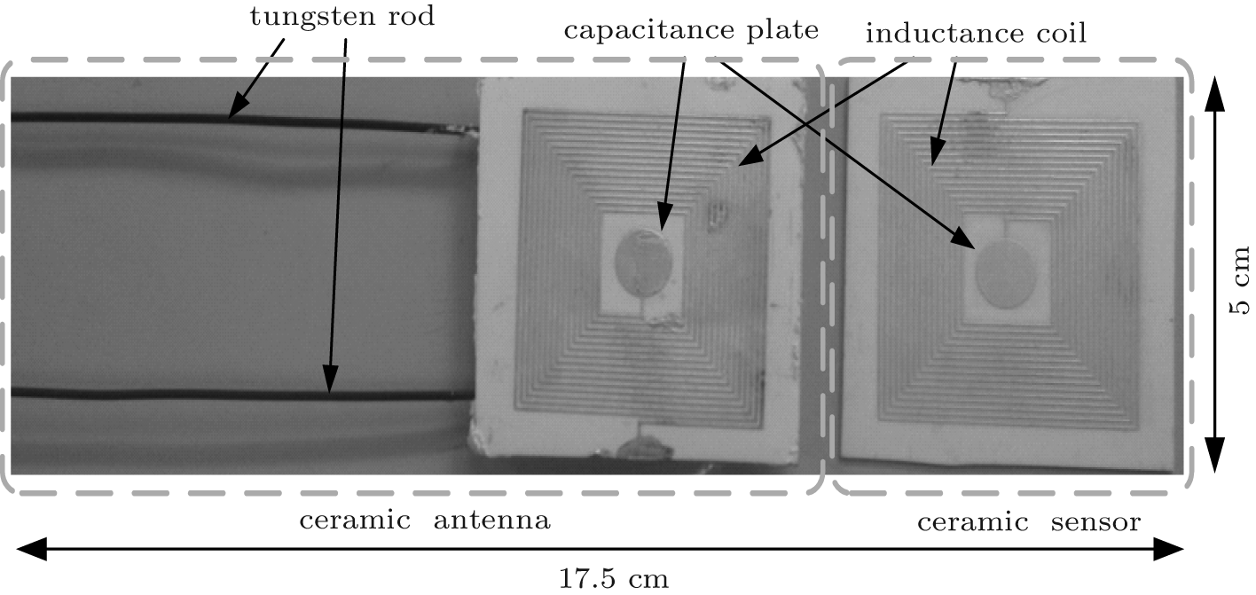
Alumina ceramic tapes, tungsten rod, and conductive silver ink 6142D are used for fabricating the antenna and sensor. The antenna and sensor are monolithically fabricated as shown in Fig. 2. The fabrication processes start with the pretreatment of the ceramic tapes in a drying oven at 80 ° C for 30 min. The sensor and antenna structure consist of three layers. (i) The first layer consists of one sheet of ceramic tape. (ii) The second layer, for the antenna, is the same as the first layer. For the sensor, the second layer is cut by the NDYAG micromachining laser system (Rofin Standard), a punching machine that cuts an accurate cavity using a designed punch file. Then, the carbon film is punched out in the same size as the diaphragm in the chamber by using the same punching file, and the cavity is filled with carbon film. (The carbon film will volatilize to form a sealed cavity during co-firing.) (iii) The third layer consists of one sheet of ceramic tape. The layers are stacked together under a certain temperature and pressure, so that they are tightly bonded to form a complete ceramic substrate. The final stack is sintered in a box furnace for ceramic substrate curing. After firing, the capacitance and inductance of the antenna and sensor are fabricated using screen-printing technology. For the antenna, the tungsten rod is placed on the ceramic substrate to establish a connection between the LC series resonance circuit on the ceramic substrate and the exterior. Then, the printed tapes for the antenna and sensor are sintered in a furnace at a peak temperature of 875 ° C and a total firing time of approximately 80 min for silver ink curing. Figure 3 shows the final fabricated ceramic antenna and ceramic sensor with identical inductance and capacitance.
Fig. 3. Photographs of the fabricated ceramic antenna and ceramic sensor.
4. Experiments and results
The fabricated ceramic antenna and ceramic sensor are tested using an E4991A impedance analyzer for electrical parameters. Because the antenna and sensor are fabricated using the same design parameters and fabrication technology, they have the same inductance, capacitance, and resistance. The experimental results are listed in Table 1, which are fully consistent with the design requirements.
Table 1.
Table 1.
Table 1. Measured electrical parameters of fabricated ceramic antenna and ceramic sensor.
Parameters
Ceramic antenna
Ceramic sensor
Inductance
∼ 8.18 μ H
∼ 8.35 μ H
Capacitance
∼ 4.414 pf
∼ 4.377 pf
Resistance
∼ 9.83 Ω
∼ 9.35 Ω
Resonant frequency
∼ 26.5 MHz
∼ 26.34 MHz
Table 1. Measured electrical parameters of fabricated ceramic antenna and ceramic sensor.
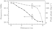
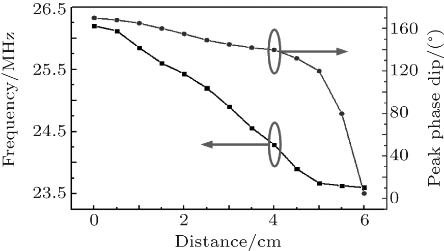
Figure 4 shows the measured resonant frequency of the sensor and impedance phase dip each as a function of coupling distance between the sensor and antenna. From Fig. 4, we observe that the resonant frequency of the sensor decreases as the working distance increases, and the phase dip drops dramatically and reaches approximately 0° at 6 cm, which is the minimum observable phase dip distance.
Fig. 4. Measured resonant frequency and impedance phase dip versus coupling distance between the sensor and antenna.
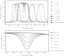
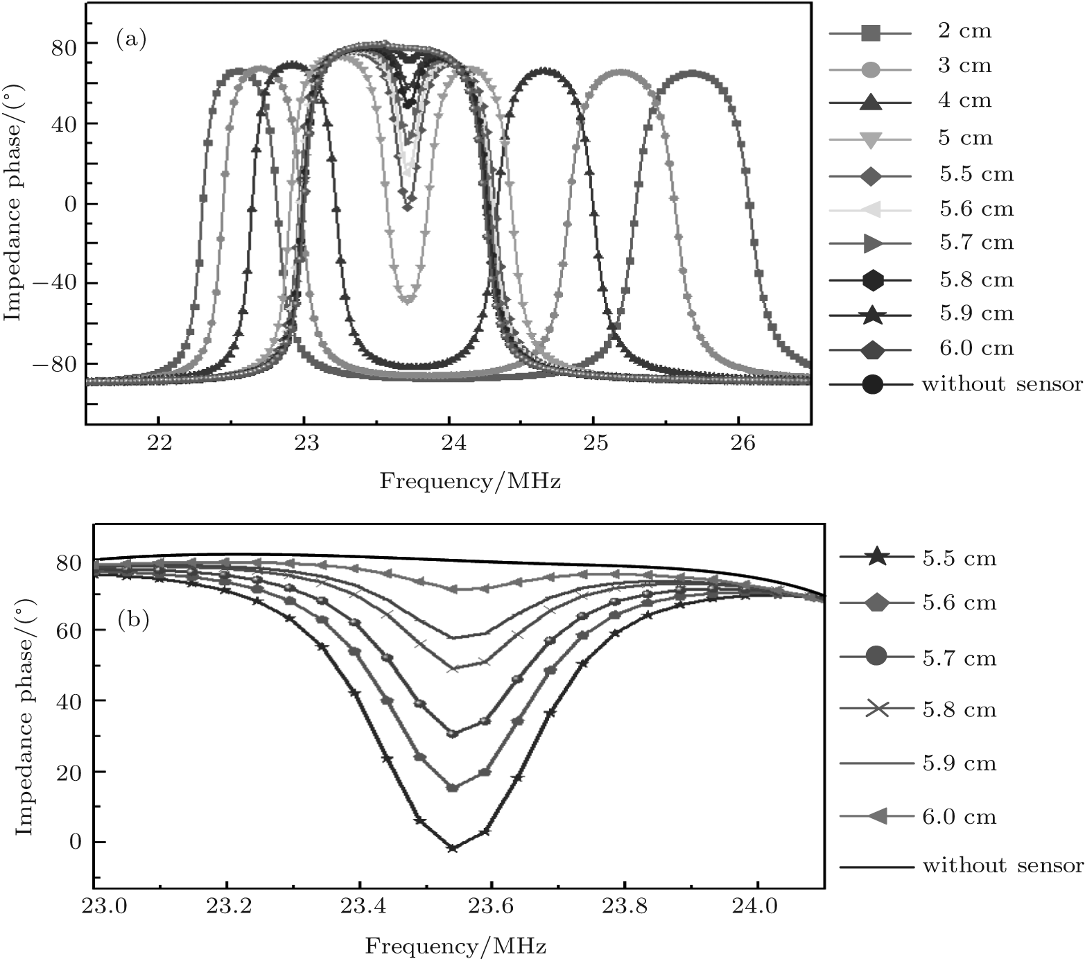
Figure 5 shows the coupling strength as a function of sensing distance between the sensor and antenna. From Fig. 5, we can see that the coupling distance between the sensor and antenna can reach up to 6 cm. Beyond the distance, the sensor cannot be coupled with the antenna, and the coupling signal between the sensor and antenna cannot be wirelessly detected. Therefore, the maximum sensing distance is 6 cm, which is more than twice the distance found by Tan et al.[13]
Fig. 5. Coupling strength as a function of sensing distance between the sensor and antenna.
To determine the pressure characterization of the achieved sensor as a function of temperature and pressure, the sensor, coupled with the ceramic antenna, is characterized on a high-temperature pressure testing system platform, which is shown in Fig. 6. The temperature can be controlled accurately from room temperature up to 600 ° C, and the pressure can be controlled accurately between 0 bar– 1 bar (the unit 1 bar = 105 Pa). During the measurement, the sensor is implanted on the heating platform and the ceramic antenna couples with the antenna at a certain distance, so the sensor and antenna are exposed to high-temperature environments. The impedance magnitude and phase of the sensor, as a function of temperature from room temperature to 600 ° C at atmospheric pressure, are investigated, and the data are captured by the E4991A impedance analyzer as shown in the following figure (Fig. 7).
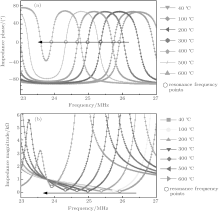
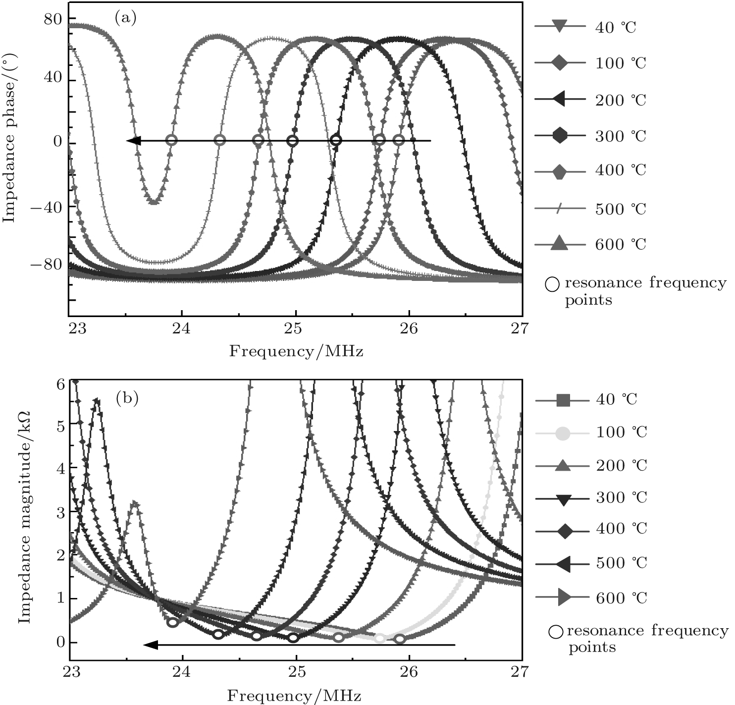
Fig. 7. Measured impedance phases (a) and impedance magnitudes (b) versus frequency, from 40 ° C to 600 ° C.
From Fig. 7, we can see that the sensor has a good coupling effect in elevated temperatures, and the impedance magnitude and impedance phase of the sensor can be detected clearly at 600 ° C. The coupling effect between the antenna and sensor becomes weaker as the temperature increases. The resonant frequency of the sensor at room temperature is approximately 25.9 MHz, and the resonant frequency is 22.4 MHz at 600 ° C. The average slope of the sensor resonant frequency is about − 2.5 kHz· ° C− 1 in a range from room temperature to 600 ° C.
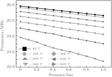
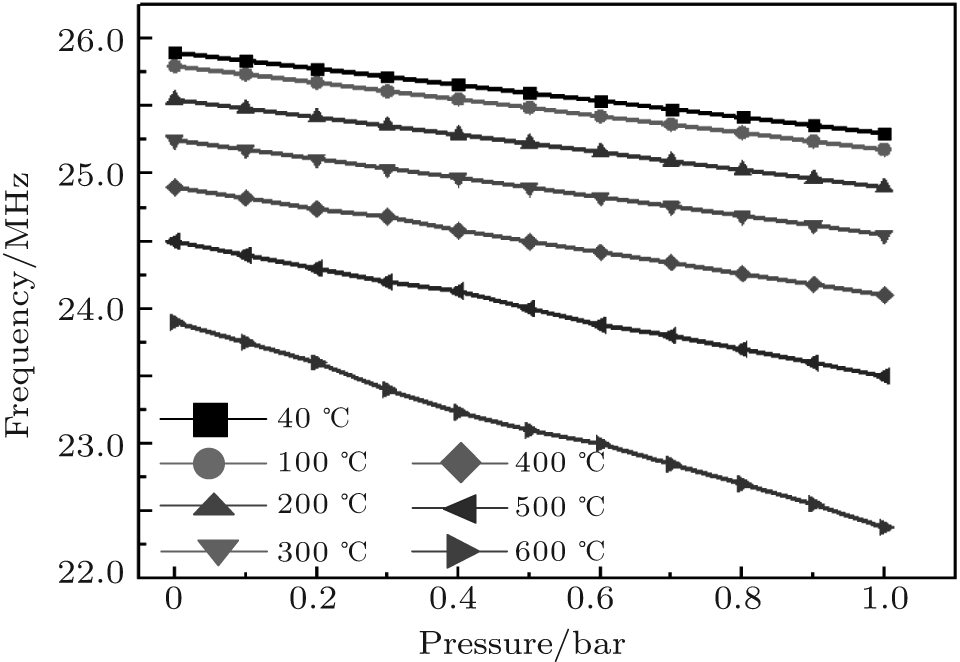
The sensor exhibits different pressure characteristic curves at elevated temperatures as shown in Fig. 8. From Fig. 8, we can see that the resonant frequency of the sensor depends approximately linearly on P, and as temperature increases the sensitivity of the sensor will increase at a constant rate. The sensitivity of the sensor is about 1.1 MHz/bar at room temperature, which changes to about 1.5 MHz/bar at 600 ° C.
Fig. 8. Resonant frequencies of the sensor versus pressure from 0 bar– 1 bar at elevated temperatures.
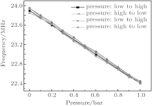
Many repeated pressure experiments on the sensor at 600 ° C are carried out. The pressure is varied in order to investigate the pressure characterization of the sensor. The measurement results are shown in Fig. 9. From Fig. 9, we can see that the sensor achieves a hysteresis of 5.5%, a repeatability error of 6.4%, and a linearity of 95.3% from 0 bar to 1 bar at 600 ° C. From the above measurement results, we conclude that the ceramic antenna and sensor can be applied to the contactless pressure measurement in high-temperature environments.
Fig. 9. Pressure responses of the sensor at 600 ° C.
5. Conclusions
In this study, we successfully demonstrate a novel design and fabrication method of an antenna. The fabrication of the antenna is similar to that of the sensor, which increases the working temperature of the antenna and improves the working distance between the sensor and antenna. The high-temperature pressure characterizations of the sensor are investigated by using an experimental measurement system to verify that the antenna and sensor can achieve a contactless pressure measurement in high-temperature environments. The experimental results show that the maximum coupled distance between the sensor and antenna is up to 6 cm, and that the pressure signal can be wirelessly detected in high-temperature environments.
In the future, we will focus on wide temperature and pressure ranges of sensor specifications. The sensor will be likely to be used in various high-thermal stress environments to measure accurate pressure variations in the aeronautics, aerospace, and automotive industries.
QiuH C, DaraF, WuX Z and HelmutS2014Chin. Phys. B23027701DOI:10.1088/1674-1056/23/2/027701[Cited within:1][JCR: 1.148][CJCR: 1.2429]
2
XiangX Y, WangK R, YuanJ H, JinB Y, SangX Z and YuC X2014Chin. Phys. B23034206DOI:10.1088/1674-1056/23/3/034206[Cited within:1][JCR: 1.148][CJCR: 1.2429]
3
MuhammadT S, KarimovK S, KhalidF A, AbbasaS Z and BhattyaM B2013Chin. Phys. B22010701DOI:10.1088/1674-1056/22/1/010701[Cited within:1][JCR: 1.148][CJCR: 1.2429]
FonsecaM A2007 “Polymer/Ceramic Wireless MEMS Pressure Sensors for Harsh Environments: High Temperature and Biomedical Applications”Ph. D. Thesis(Georgia Institute of Technology)(in USA)[Cited within:1]
13
TanQ L, KangH, XiongJ J, QinL, ZhangW D, LiC, DingL Q, ZhangX S and YangM L2013Sensors139896DOI:10.3390/s130809896[Cited within:2][JCR: 1.953]
... 4] One possible solution to this problem is to supply power to the sensor by means of magnetic field radiation, which does not require the sensor to be powered using batteries ...
1
2008
0.0
0.0
... [5] For the high-temperature environments there is growing demand for measuring pressure parameters, which are still difficult to determine ...
1
2001
5.165
0.0
... [6] Recently, some high-temperature pressure sensors based on ceramics have been developed ...
1
1967
2.348
0.0
... [7#cod#x02013 ...
1
2003
1.475
0.0
1
2008
0.0
0.0
1
2010
0.0
0.0
... 10] The contactless wireless measurement method can accurately monitor pressure in harsh environments, since it can provide the possibility of the sensor on moving parts, and reduce potential unreliable contacts by the sensor ...
1
2002
0.0
0.0
... [11] and Fonseca[12] developed a wireless passive capacitive high-temperature pressure sensor based on low-temperature co-fired ceramic (LTCC) technology, but it can only work at up to 450 #cod#x000B0 ...
1
2007
0.0
0.0
... [11] and Fonseca[12] developed a wireless passive capacitive high-temperature pressure sensor based on low-temperature co-fired ceramic (LTCC) technology, but it can only work at up to 450 #cod#x000B0 ...
2
2013
1.953
0.0
... ,[13] and Xiong et al ...
... [13] ...
1
2013
0.0
0.0
... [14,15] designed two sensors based on LTCC and high-temperature co-fired ceramic technologies (HTCC) ...
1
2013
0.0
0.0
... [14,15] designed two sensors based on LTCC and high-temperature co-fired ceramic technologies (HTCC) ...
Wireless contactless pressure measurement of an LC passive pressure sensor with a novel antenna for high-temperature applications*
[Li Chena),b), Tan Qiu-Lina),b)†, Xue Chen-Yanga), Zhang Wen-Dongb), Li Yun-Zhib), Xiong Ji-Junb)‡]


 , Xue Chen-Yang