


Numerical simulation and analysis of complex patterns in a two-layer coupled reaction diffusion system*
[Li Xin-Zhenga) , Bai Zhan-Guoa)†  , Li Yan
a) , He Ya-Fengb) , Zhao Kuna) ]
, Li Yan|
|


†Corresponding author. E-mail: baizg2006163@163.com
*Project supported by the National Natural Science Foundation of China (Grant No. 11247242), the Young Scientists Fund of the National Natural Science Foundation of China (Grant No. 51201057), and the Natural Science Foundation of Hebei Province, China (Grant No. A2014208171).
The resonance interaction between two modes is investigated using a two-layer coupled Brusselator model. When two different wavelength modes satisfy resonance conditions, new modes will appear, and a variety of superlattice patterns can be obtained in a short wavelength mode subsystem. We find that even though the wavenumbers of two Turing modes are fixed, the parameter changes have influences on wave intensity and pattern selection. When a hexagon pattern occurs in the short wavelength mode layer and a stripe pattern appears in the long wavelength mode layer, the Hopf instability may happen in a nonlinearly coupled model, and twinkling-eye hexagon and travelling hexagon patterns will be obtained. The symmetries of patterns resulting from the coupled modes may be different from those of their parents, such as the cluster hexagon pattern and square pattern. With the increase of perturbation and coupling intensity, the nonlinear system will convert between a static pattern and a dynamic pattern when the Turing instability and Hopf instability happen in the nonlinear system. Besides the wavenumber ratio and intensity ratio of the two different wavelength Turing modes, perturbation and coupling intensity play an important role in the pattern formation and selection. According to the simulation results, we find that two modes with different symmetries can also be in the spatial resonance under certain conditions, and complex patterns appear in the two-layer coupled reaction diffusion systems.
Patterns are widely observed in the chemical, nonlinear optical, biological, and physical systems. Although the specific physics mechanisms for pattern formation in different systems are different, the morphology and evolution of patterns have their common characteristics, and they usually result from symmetry breaking of nonlinear systems. In 1952, Turing[1] first used the reaction– diffusion mechanism to explain that a homogeneous state can lose its stability and develop a spatially stationary pattern in an organism, when instability of the homogeneous equilibrium is triggered by random disturbances. In recent years, the complex patterns have attracted much attention, and a rich variety of complex patterns have been obtained in experiment research, including the white-eye and black-eye pattern, the honeycomb hexagon pattern, the vibrating hexagonal pattern, and the grid state pattern.[2– 9]
Since Banrrio et al.[10] first proposed that the superlattice pattern may originate from the interaction between two modes in 1999, research on the complex patterns has become a challenging topic by the two-layer coupled model, and scientists have obtained plentiful achievements for the past decades. For example, Yang et al.[11] obtained the white-eye and black-eye hexagonal patterns with a two-layer coupled Brusselator model at the same time, and proved the Zhou et al. guess[12] about the black-eye hexagonal pattern. Bachir et al.[13] investigated the superlattice pattern formation in bistable systems. Page et al.[14] obtained the big-small dot super quadrilateral pattern using the Gierer– Meinhardt equation with a quadrilateral plate. Schenk[15] obtained the moving hexagon pattern by a three-component reaction– diffusion model. In general, the superlattice patterns are formed by two or more modes according to a certain wavelength relation. When resonance between two different wave vectors takes place, “ new” wave vectors will be formed, the “ new” and basic wave vectors satisfy the requirements for a three-wave or four-wave resonance mechanism.
In this paper, we mainly show the influences of the Turing mode and subharmonic Turing mode (sub-T) on pattern formation, and the evolution process of patterns with the change of parameters in the two-layer coupled nonlinear system. The rest of this paper is organized as follows. In Section 2, we introduce the reaction– diffusion model and simulation method. In Section 3, we discuss the formations of superlattice patterns and oscillation patterns. The conclusions and remarks are presented in Section 4.
There are a number of specific reaction– diffusion models used to investigate the pattern formation, such as the Lengyel– Epstein model (CIMA), the Brusselator model, and the Schnackenberg model.[16– 21] In this paper, we investigate the complex pattern formation processes by using the dimensionless two-layer coupled Brusselator model, described as follows:

where the activator u and the inhibitor v, and their corresponding diffusion coefficients, Du and Dv, are distinguished by the subscripts i, j = 1, 2, which refer to different layers. The Laplacian terms are used to describe the horizontal diffusion of the layer interfaces. The localized kinetic behavior of the system is determined by controlling parameters a and b. The coupling terms fi(ui, uj and gi(vi, vj) are given by the following functions, [22] for the linear coupling model
 |
or the nonlinear coupling model
 |
where α and β are the coupling intensities between layers. The coupling terms can be seen as an intermediate layer, which is separated into the two chemically active layers. It is an inert layer in the linear coupling model, and has no interaction with the other layers. However, it plays an active role in the nonlinear coupling model. Through choosing the appropriate parameters, two different wavelength Turing modes are excited within the Turing domain, and their wavenumbers are respectively k1 and k2. Figure 1 presents the dispersion curve of the two-layer coupled model, where the two modes have different values of wavenumber k and intensity h, which compete and interact with each other in the process of pattern formation. The intensities of the two Turing modes are affected by all parameters, but the coordinate position of the initial point of the curve in the Hopf domain is determined only by controlling parameters a and b.
In our simulation, the Euler forward algorithm is used, the two-dimensional space is divided into 128× 128 lattices, periodic boundary conditions are applied, and space step Δ x = Δ y = 1.0 and time step Δ t = 0.01 are taken. A small random perturbation around the uniform steady state and the uncertainty limits of Δ u and Δ v of 0.0∼ 0.12 are adopted. More than 1000 integration time units are used to ensure the pattern stabilization.
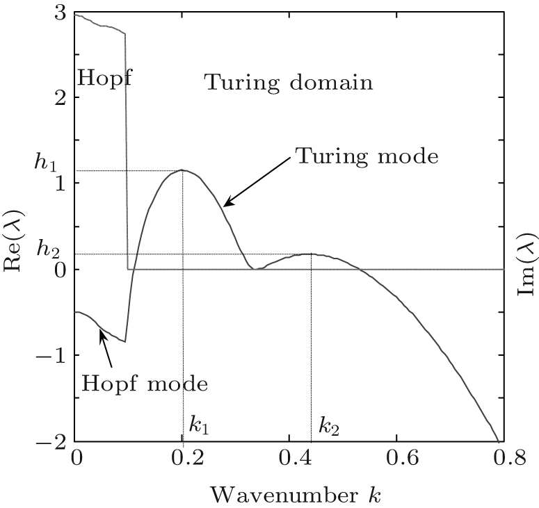 | Fig. 1. Typical dispersion relation curve, with the solid line denoting the real part of dominant eigenvalue and the dash line referring to the imaginary part. |
Firstly, we analyze the interaction between two different modes with the same hexagon symmetry in linear coupled systems for similification. We fix the parameters of long wavelength mode, considering it plays a dominant role in the pattern formation. With different parameters of the short wavelength mode, the resonance behavior and superposition patterns are investigated.
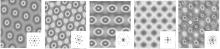
Units of superlattice patterns have the same hexagon structure since they originate from the superposition of two hexagons. When the wavenumber ratio k2 : k1 is 2:1, the black-eye and big-small dot patterns emerge in the nonlinear system, respectively. Figure 2(a) shows the black-eye hexagonal superlattice pattern, where the center of the unit is blue and surrounded by a white ring and a light-red ring. With the intensity ratio h1 : h2 changing from − 0.35 to 1.97, the big-small dot pattern will be obtained at the same wavenumber ratio (Fig. 2(b)). Each big dark dot is surrounded by six small dark dots and shared with adjacent units, and the big and small dots are arranged in a hexagon. However, if the intensity ratio of two critical modes is invariant and the wavenumber ratios are

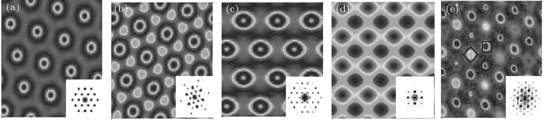 | Fig. 2. Different patterns with 2D Fourier spectrum. The parameters: (a) black-eye pattern: a = 3, b = 9, Du1 = 13.5, Dv1 = 28.95, Du2 = 50.3, Dv2 = 125.5, α = β = 0.2, Δ ν = Δ μ = 0.0; (b) big-small dot pattern: a = 3, b = 9, Du1 = 12.65, Dv1 = 31.05, Du2 = 50.3, Dv2 = 125.5, α = β = 0.25, Δ ν = Δ μ = 0.0; (c) white-eye pattern: a = 3, b = 9, Du1 = 6.05, Dv1 = 12.85, Du2 = 50.3, Dv2 = 125.5, α = β = 0.2, Δ ν = Δ μ = 0.0; (d) square pattern: a = 3, b = 9, Du1 = 6.95, Dv1 = 17.05, Du2 = 55.3, Dv2 = 147.5, α = β = 0.45, Δ u = 0.03, Δ ν = 0.01; (e) oscillatory pattern: a = 3, b = 9.9, Du1 = 8.3, Dv1 = 8.3, Du2 = 46.0, Dv2 = 120.0, α = β = 1.0, Δ ν = Δ μ = 0.0. Ref. [11]. |
Furthermore, with the increase of the diffusion coefficients of the two Turing modes, we can obtain the simple square pattern at a wavenumber ratio of 3:1 under the action of small perturbation (Fig. 2(d)), where the spots form a square lattice by adjusting their locations in the two-dimensional space. The Fourier spectrum shows the simple square pattern resulting from two pairs of equal amplitude and mutually perpendicular wave vectors. The reason is that the three-wave resonance of fundamental vectors of the long wavelength mode is broken by the coupling interaction. The oscillatory pattern is simulated by using the Yang et al.’ s parameters[11] (Fig. 2(e)), where the three sets of hexagonal patterns appear in turn and are distinguished by the different symbols, and the intensities of spots wax and wane according to the same cycle of 4.4 time units. The result is consistent with the Yang et al.’ s result, and it also demonstrates the correctness of our simulation method.
Now we investigate the case of two Turing modes with nonlinearly coupling by the same simulation program. In addition to the white-eye and black-eye patterns, more superposition patterns are obtained such as the big– small dot, honeycomb hexagon, cluster hexagon, drifting hexagon, and twinkling-eye patterns.
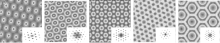
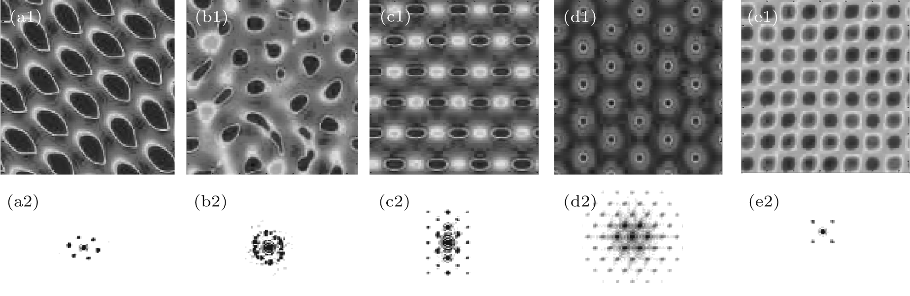
When two different modes with the same hexagon symmetry are nonlinearly coupled, the case is relatively easy to analyze. At the wavenumber ratios of 2:1 and 3:1, the black-eye and white-eye patterns will emerge respectively (Figs. 3(a) and 3(b)). When the two different Turing modes are instable modes and the wavenumber ratio is close to 3:1, two kinds of big– small dot patterns are also obtained (Figs. 3(c) and 3(d)), which are very like the vibrating hexagonal superlattice pattern discovered in dielectric barrier discharge.[23] In the first big– small dot hexagonal superlattice pattern, big bright spots are located in each hexagon frame constituted by the small spots, and each of the big spots is surrounded by six small bright spots and shared with adjacent units. When the intensity ratio of two Turing modes increases from 3 to 12, the second big– small dot hexagon pattern is obtained, where each of the big bright spots is surrounded by six dark spots and shared with adjacent units. When the wavenumber ratio of two Turing modes is around 4:1, the honeycomb hexagon pattern is discovered (Fig. 3(e)). The honeycomb is formed by an equilateral hexagon and the center space of the hexagon is a big bright spot with its halo. The two-dimensional Fourier spectrums show that these complex patterns are formed by multiple Turing modes, and these modes satisfy the three-wave resonance relations. Although the simple hexagon patterns have never changed in the long wavelength mode subsystem, these complex patterns can be obtained from the resonance of two different wavelength modes in a short wavelength mode subsystem.
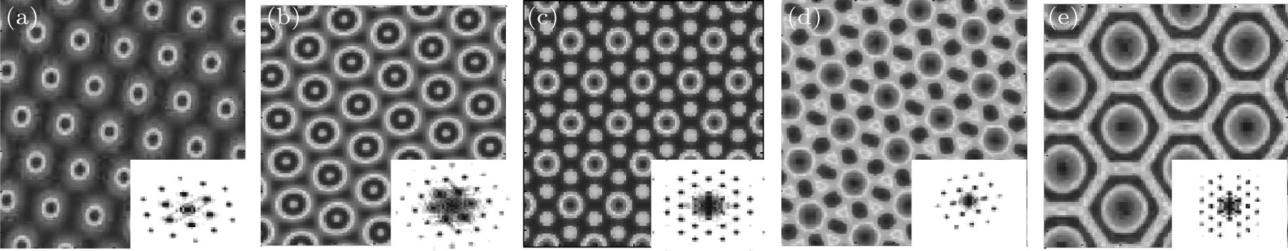 | Fig. 3. Different patterns with 2D Fourier spectrum. The parameters (a) black-eye pattern: Du1 = 6.55, Dv1 = 13.8, Du2= 22.5, Dv2 = 65.5, α = 0.08, β = 0.02; (b) white-eye pattern: Du1 = 2.95, Dv1 = 6.15, Du2 = 22.5, Dv2 = 65.5, α = 0.08, β = 0.02; (c) I-big– small dot pattern: Du1 = 5.0, Dv1 = 19.75, Du2 = 22.95, Dv2 = 355.5, α = β = 0.03; (d) II-big– small dot pattern: Du1 = 7.22, Dv1 = 18.2, Du2 = 31.93, Dv2 = 255.15, α = β = 0.02; (e) honeycomb pattern: Du1 = 6.1, Dv1 = 16.78, Du2 = 62.5, Dv2 = 437.53, α = β = 0.03. The other parameters: a = 3, b = 9, Δ μ = 0.03, and Δ ν = 0.01. |
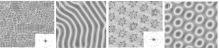
Figures 4(a) and 4(b) show the irregularly different density stripe patterns, which result from the short and long wavelength modes without coupling interaction. Under the action of nonlinear coupling, the cluster hexagon pattern appears in the short wavelength subsystem, at the same time, the simple HΠ hexagon pattern emerges in the long wavelength subsystem (Figs. 4(c) and 4(d)). The clusters consist of dots and short stripes, and they are arranged into a hexagonal lattice. If transverse instability occurs in the stripe pattern, the symmetry of the stripe pattern may be broken, and the hexagon pattern and square pattern will arise in the nonlinear system. Based on the characteristic of two-dimensional Fourier spectra, the coupled Turing modes should satisfy the spatial resonance condition.
When two instability modes with different symmetries are nonlinearly coupled, the case will be more complicated. Without coupling interaction and perturbation, a simple hexagon pattern arises in the short wavelength mode subsystem, and a stripe pattern appears in the long wavelength mode at a wavenumber ratio of 4:1 (Fig. 5(a)). The dispersion relation shows that the wavenumber ratio k2 : k1 is about 4:1, and the intensity of the short wavelength mode is less than that of the long wavelength mode (Fig. 6(a)). However, when the two different wavelength Turing modes are nonlinearly coupled, a variety of complicated patterns appears under the action of small perturbations.
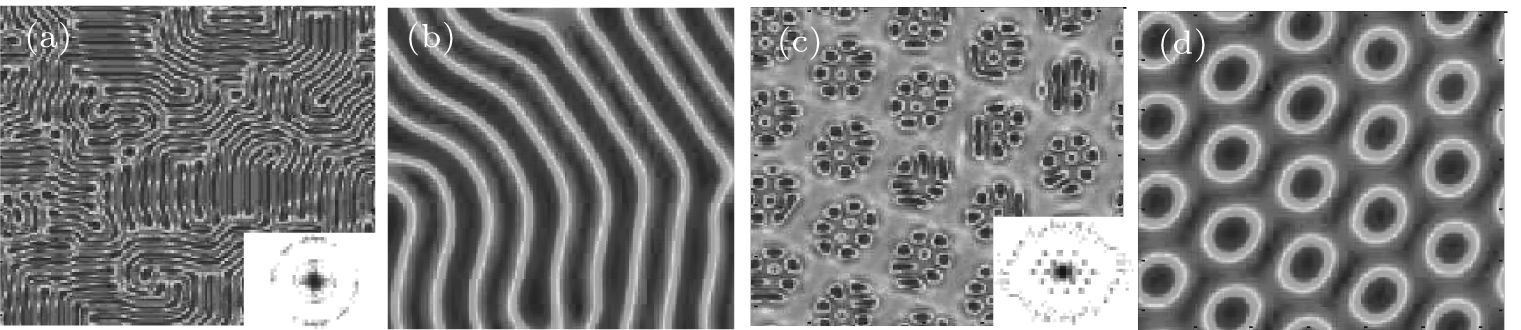 | Fig. 4. (a) and (b) Non-coupled patterns from layer 1 and layer 2, respectively (α = β = 0.0). (c) and (d) The coupled patterns from layer 1 and layer 2, respectively (α = β = 0.055). The other parameters: a = 3, b = 9, Du1= 1.75, Dv1 = 5.05, Du2 = 30.5, Dv2 = 95.5, and Δ ν = Δ μ = 0.02. |
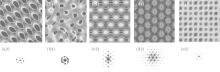
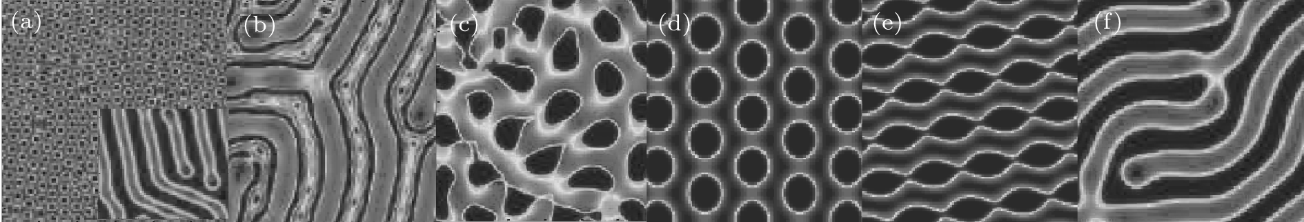 | Fig. 5. A series of patterns obtained by increasing parameters α and β (α = β ): (a) α = β = 0, (b) α = β = 0.05, (c) α = β = 0.15, (d) α = β = 0.2, (e) α = β = 0.25, (f) α = β = 0.5. The other parameters are: a = 3, b = 9, Du1 = 1.86, Dv1 = 4.66, Du2 = 29.75, Dv2 = 129.25, and Δ ν = Δ μ = 0. |
We first investigate the influences of coupling intensity on the pattern formation and selection. When the coupling intensity is smaller than 0.1, the dot-stripe patterns appear (Fig. 5(b)), and the spots occupy the space between the stripes. When the coupling intensity is in the range 0.1– 0.2, the dynamic chaos patterns emerge, which consist of the irregular spots and short stripes (Fig. 5(c)). The spots of patterns randomly travel along the direction of the halo, and adjacent dots or short stripes can collide and fuse together within the simulation time. At an intensity of 0.2, the spots of the pattern gradually stabilize and are arranged into a hexagon lattice (Fig. 5(d)). The transition from hexagon patterns to stripe patterns occurs in a range of 0.2– 0.3, where the bean pattern is a transition mode (Fig. 5(e)). In the range 0.3– 1.0, simple stripe patterns appear (Fig. 5(f)). With the increase of coupling intensities α and β , the patterns go through the stages of dot-stripe → oscillation → hexagon → bean → stripe. Based on the pattern characteristics, we conclude that the nonlinear system is always in the vicinity of the primary bifurcation point. We pay much attention to the dispersion curves changing with coupling parameter. Figure 6(a) shows that the dispersion curve overall shifts down with the coupling intensity except for the initial point in the Hopf domain, the short wavelength Turing mode is more obviously affected than the long wavelength Turing mode, and the subharmonic Turing mode is excited. The intensity ratio of two Turing modes changes with the coupling parameter, and the influence of long wavelength mode on short wavelength mode increases. When coupling intensity increases to 0.05, the short wavelength mode becomes a critical mode, and a dot-stripe pattern appears. When the coupling intensity is 0.10, the peak of the short wavelength mode drops down almost to the height of the initial point, at the same time, the spots of two subsystems enter into a dynamic state but cannot form a regular pattern. In the range 0– 0.3, the intensity of the short wavelength mode decreases linearly, but the intensity of the long wavelength mode gradually reduces the decline rate with the coupling intensity (Fig. 6(b)). When the peak of the short wavelength mode is lower than the initial point of the dispersion relation curve, we deduce that the Hopf instability happens in the nonlinear system, and the dynamic patterns appear; otherwise, Turing instability happens, and the static patterns appear.
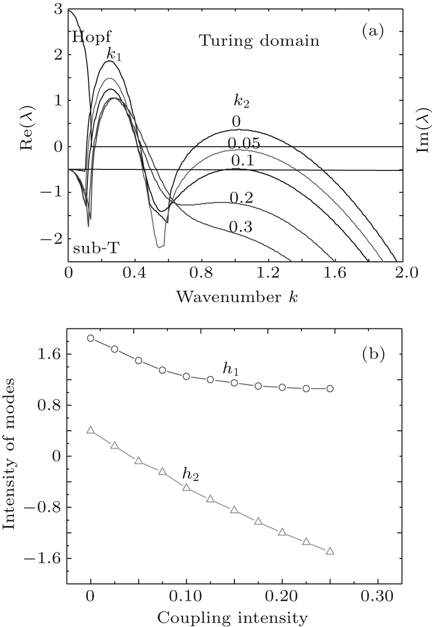 | Fig. 6. (a) Dispersion relation curves of Turing modes and sub-T mode at different coupling intensities, and (b) the curves of intensity versus coupling intensity of two Turing modes intensity. |
Now we investigate the influence of perturbation on the pattern formation by using Fig. 5(c) as the research object. When the perturbation coefficient is in the range 0.01– 0.06, the uniformly drifting patterns appear after some transient oscillations (Fig. 7(a)), and the simulation phenomenon is consistent with the experimental results of Loiko and Yu[24] and Dong et al.[25] The shuttle-shape spots are arranged into a hexagonal lattice, all units slowly move along the direction of the arrow shown, and the moving velocity of shuttle-shape spot fluctuates with the increase of the perturbation coefficient. Then, when the perturbation coefficient rises to 0.07, some units of the pattern no longer participate in the directional movement, and gradually shrink or even disappear (Fig. 7(b)). In the range 0.08– 0.1, the periodic oscillation pattern appears (Fig. 7(c)) in the short wavelength mode subsystem, which was named the twinkling-eye pattern by Yang et al.[11] Figures 8(a)– 8(h) show a periodic variation of intensity, where the twinkling-eye hexagon patterns consist of two sets of hexagons distinguished by the different intensity spots, the oscillatory period is about 20 time units, and the phase difference is π . At 0.1, not only the twinkling-eye pattern but also a static black-eye hexagon pattern can be obtained. At 0.11 and 0.12, we find the black-eye hexagon pattern and the simple square pattern in Figs. 7(d) and 7(e), respectively. However, when the perturbation coefficient is more than 0.12, there is no pattern in the system, that is to say, the perturbation must be restricted within a certain range. With the increase of the perturbation coefficient, patterns go through the stages of drifting hexagon, twinkling-eye hexagon, black-eye hexagon, and square. Fourier spectra show that all patterns have the fundamental modes with equal length, and the twinkling-eye and black-eye patterns result from the three-wave interaction of different length modes. From the Fourier spectrum and dispersion relations, we infer that the fundamental mode should be the sub-T mode, which becomes a dominant one. Based on the existing conclusions, the dynamic pattern results from the two mechanisms: Hopf instability and wave instability. Therefore, the drifting hexagon pattern and periodic oscillation hexagon pattern should result from the Hopf instability. If Hopf instability happens in the nonlinear system, the drifting hexagon pattern appears when the mode satisfies the spatiotemporal phase matching conditions under the action of small perturbation, and the twinkling-eye hexagon pattern appears when the sub-T mode is in resonance with the long wavelength Turing mode. On the other side, black-eye hexagon and simple square patterns are obtained. We can deduce that the perturbation coefficient affects not only the type of instability, but also the resonance of modes with different wavelengths in the two-layer coupled system.
 | Fig. 7. The series of patterns with spatial power spectra are obtained by increasing perturbation coefficient Δ ν and Δ μ (Δ ν = Δ μ ): (a) Δ ν = Δ μ = 0.03, (b) Δ ν = Δ μ = 0.07, (c) Δ ν = Δ μ = 0.08, (d) Δ ν = Δ μ = 0.11, (e) Δ ν = Δ μ = 0.12. The other parameters are: a = 3, b = 9, Du1 = 1.86, Dv1= 4.66, Du2 = 29.75, Dv2 = 129.25, and α = β = 0.15. |
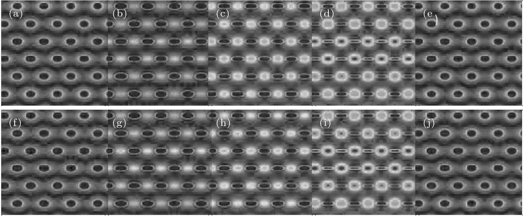 | Fig. 8. A series of patterns in chronological orders (t → t+ T): 540, 545.4, 546.6, 547.6, 549.8, 550.4, 555.6, 556.2, 557.6, and 560 time units. The simulation parameters are: a = 3, b = 9, Du1 = 1.86, Dv1 = 4.66, Du2 = 29.75, D2 = 129.25, α = β = 0.15, and Δ ν = Δ μ = 0.08. |
In this paper, we investigate the pattern formation using two kinds of simulation methods: the two-layer linear coupled model and the two-layer nonlinear coupled model. When Turing instability happens in a nonlinear system, various types of static superlattice and simple patterns, such as white-eye and black-eye, honeycomb hexagon, square, and cluster hexagon, are obtained in a short wavelength mode subsystem. If the appropriate intensity ratio of two different wavelength modes can be obtained, the superlattice patterns will appear in the short wavelength mode subsystem when the coupling intensity is less than 0.1. The drifting hexagon and periodic oscillation hexagon patterns are discovered when Hopf instability happens in the nonlinear system, and the sub-T mode plays a major role in the pattern formation. Modes with the same symmetry and modes with different symmetries may both induce spatial resonance under the action of perturbation and coupling interaction. With the increase of coupling intensity and perturbation, both static patterns and dynamic patterns can appear in the two-layer coupled reaction diffusion system. We find that if the short wavelength mode has hexagon symmetry, both a simple hexagon pattern and square pattern arise spontaneously. Our results may enrich the pattern formation mechanism and give a better understanding of the complex patterns in the nonlinear system.
| 1 |
|
| 2 |
|
| 3 |
|
| 4 |
|
| 5 |
|
| 6 |
|
| 7 |
|
| 8 |
|
| 9 |
|
| 10 |
|
| 11 |
|
| 12 |
|
| 13 |
|
| 14 |
|
| 15 |
|
| 16 |
|
| 17 |
|
| 18 |
|
| 19 |
|
| 20 |
|
| 21 |
|
| 22 |
|
| 23 |
|
| 24 |
|
| 25 |
|