
Synthesis and electrochemical properties of three-dimensional graphene/polyaniline composites for supercapacitor electrode materials*
[Zhao Wen, He Da-Wei† , Wang Yong-Sheng, Du Xiang, Xin Hao]
, Wang Yong-Sheng, Du Xiang, Xin Hao]
|
|


†Corresponding author. E-mail: dwhe@bjtu.edu.cn
*Project supported by the National Basic Research Program of China (Grant Nos. 2011CB932700 and 2011CB932703), the National Natural Science Foundation of China (Grant Nos. 61335006, 61378073, and 61077044), the Beijing Natural Science Foundation, China (Grant No. 4132031), and the Fundamental Research Funds for the Central Universities of Beijing Jiaotong University, China (Grant No. 2014YJS136).
To improve the specific capacitance and rate capability of electrode material for supercapacitors, a three-dimensional graphene/polyaniline (3DGN/PANI) composite is prepared via in situ polymerization on GN hydrogel. PANI grows on the GN surface as a thin film, and its content in the composite is controlled by the concentration of the reaction monomer. The specific capacitance of the 3DGN/PANI composite containing 10 wt% PANI reaches 322.8 F·g−1 at a current density of 1 A·g−1, nearly twice as large as that of the pure 3DGN (162.8 F·g−1). The capacitance of the composite is 307.9 F·g−1 at 30 A·g−1 (maintaining 95.4%), and 89% retention after 500 cycles. This study demonstrates the exciting potential of 3DGN/PANI with high capacitance, excellent rate capability and long cycling life for supercapacitors.
Supercapacitors are widely recognized as an important class of clean and sustainable energy storage devices. They are attractive for energy storage because of their fast charging capability, long cycle life and high energy density.[1– 4] Recently, an intriguing result has been found in which a unique carbon material, graphene (GN), shows excellent conductivity, high surface area and good mechanical strength.[5]
Graphene obtained by reduced graphene oxide has the advantages of potentially low cost and solution processed fabrication. However, chemical reduced graphene has the tendency of agglomeration because of the strong interlayer π – π stacking, which results in minimal surface area. Three-dimensional graphene (3DGN) effectively prevents the problem from stacking.[6] Additionally, its macroporous framework is in favor of the ionic and electronic transport in electrodes for supercapacitors. 3DGN material can be directly used as a binder-free electrode with excellent rate capability and cycling stability. However, the pure 3DGN is still limited in the specific capacitance (100 F· g− 1 ∼ 240 F· g− 1).[7– 10] To overcome this limitation, it is essential to extend our focus to composite materials comprising 3DGN and pseudocapacitive materials.[11, 12]
For pseudocapacitors, conductive polymers as a promising electrode material have been extensively explored, due to their light weight, high conductivity and low cost. Polyaniline (PANI) is the most potential conductive polymer. It has additional excellent properties including its facile synthesis and acid/base doping chemistry.[13, 14] Caused by the doping and dedoping process, PANI also presents the low rate capability and lifetime stability.[15] Thus, the combination of 3DGN with PANI seems to be a prospective approach to having a synergic effect on improving the performance of supercapacitors. Yang et al. prepared GN/PANI hybrid aerogels through the hydrothermal route using PANI nanowires as spacers. The specific capacitance of PAGO (1:1) was 520.3 F· g− 1 at 0.25 A· g− 1 and ∼ 340 F· g− 1 at 2 A· g− 1.[16] Chemical converted graphene/PANI nanofibers film was fabricated through filtration by Wu et al. with the electrochemical capacitance of 210 F· g− 1 at a discharge rate of 0.3 A· g− 1.[17] Liu et al. prepared the free-standing GN/PANI paper via electrostatic adsorption, obtaining a specific capacitance of 301 F· g− 1 at a current density of 0.5 A· g− 1 and 201 F· g− 1 after 400 cycles.[18] Although the capacitances in these studies were relatively high, they were measured at low current densities and under these conditions the GN/PANI composites displayed a poor rate capability.
In this paper, we present the high performance of graphene hydrogel as a 3D structure composed of PANI by an in situ polymerization method. The composite of 3DGN/PANI exhibits a high specific capacitance (322.8 F· g− 1 at 1 A· g− 1), excellent rate capability (95.4% retention at 30 A· g− 1), and long cycling life with maintaining 89% capacitance over 500 charge/discharge cycles at a current density of 30 A· g− 1. The high performance of 3DGN/PANI demonstrates that this composite is a potential candidate as an electrode material for future energy storage systems.
The graphene oxide (GO) was initially prepared from natural graphite by the Hummers and Offeman's method.[19] The GN hydrogel was prepared according to the method described by Chen and Yan.[20] The as-prepared GO suspension was dispersed in deionized water (2 mg· mL− 1) by a sonication process to obtain a homogeneous GO dispersion (1.5 mL) and then the GO dispersion was chemically reduced by sequentially adding 6 mg of ascorbic acid. Successively, the dispersion was kept at 90 ° C for 3 h to produce the 3DGN. The impurity was further removed by dialysis.
The 3DGN was immersed in a 3-mL of 1-M HCl aqueous solution containing 0.045 mL of aniline (ANI) monomer and this mixture was store at 0 ° C for 1 h. Another 3 mL of 1-M HCl aqueous solution dissolving 0.0225-g ammonium perxydisulfate (APS) was cooled to 0 ° C for 1 h. The two HCl aqueous solutions above were mixed together and immediately shaken for 30 s. After 12-h standing at 0 ° C, the resulting hydrogel from mixing two HCl aqueous solutions was then thoroughly rinsed by 1-M HCl aqueous solution and deionized water.
To measure the weight fraction of PANI in the 3DGN/PANI, both the 3DGN and 3DGN/PANI with the same sizes (1.2 mm in diameter and 1 mm in thickness) were dried at 90 ° C overnight before weighing and calculating. We obtained the weight fraction of PANI of 10 wt% in this 3DGN/PANI, denoted as 3DGN/PANI10% here. In this work, the concentration of ANI (keeping the same ratio of ANI to APS) was controlled to achieve various loading amounts of PANI with the 3DGN/PANI. According to the amounts of ANI of 0.023 mL, 0.090 mL, and 0.135 mL, the mass ratios of PANI in 3DGN/PANI were 5.6% , 19% , and 37% respectively.
The as-prepared hydrogels (3DGN and 3DGN/PANI10% ) were freeze-dried and their morphologies were characterized with scanning electron microscopy (SEM, HITACHI S-4800) and transmission electron microscopy (TEM, JEM-1400 operating at 120 kV). The x-ray diffraction (XRD) data were obtained by a Bruker D8 ADVANCE using Cu Kα radiation. Fourier transform infrared spectroscopy (FTIR) investigation was employed using an IR spectrophotometer (Thermo Fisher Nicolet 6700). Micro-Raman spectroscopy (Thermo Fisher DXR) was used to further study the structure of the samples. The specific surface area (SSA) was calculated using the Brunauer– Emmett– Teller (BET) method by APP V-Sorb 2008P, and the pore size distribution curves were obtained by analyzing the N2 desorption isotherms using the Barrett Joyner Halenda (BJH) method.
All electrochemical properties were studied by an electrochemical workstation (CHI660E), using a two-electrode configuration. The as-prepared hydrogels soaked in 1-M H2SO4 aqueous were used as electrodes and the graphite paper was used as the current collector. We collected cyclic voltammetry (CV) curves with a potential window from 0 V to 1 V at different scan rates ranging from 20 mV· s− 1 to 500 mV· s− 1. Galvanostatic charge/discharge (GCD) measurements were running from 0 V to 1 V at different current densities, and electrochemical impedance spectroscopy (EIS) measurements were recorded from 0.01 Hz to 100 kHz with an AC-voltage amplitude of 5 mV.
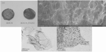
The image including the 3DGN and the composite of 3DGN/PANI after being freeze-dried is shown in Fig. 1(a). The pure 3DGN has a slightly metallic luster and the composite is blue-black after having been compounded with PANI. Figures 1(b) and 1(d) show the SEM and TEM images of 3DGN. The 3DGN is formed by partial overlapping of GN sheets via hydrophobic and π – π interactions in 3D space and possess a porous network with several micrometer pores. After 3DGN is compounded with PANI, the SEM image of the composite (3DGN/PANI) (see Fig. 1(c)) shows no evident difference from that of 3DGN. From the TEM image of the composite (Fig. 1(e)) it follows that the short PANI nanowire arrays are distributed on the surface of GN parallelly and perpendicularly. ANI monomers are adsorbed on the GN surface by electrostatic attraction and π – π stacking.[21, 22] As the APS solution is added, the polymerization of ANI monomer takes place on the GN surface. These images above confirm that the 3DGN/PANI composite has been synthesized successfully.
 | Fig. 1. (a) Digital images of 3DGN and 3DGN/PANI after having been freeze-dried; (b) SEM image of 3DGN; (c) SEM image of 3DGN /PANI; (d) TEM image of 3DGN; (e) TEM image of 3DGN /PANI. |
We first discuss the composite of the thin film on 3DGN using FTIR. The FTIR spectra of GO, 3DGN and 3DGN/PANI are shown in Fig. 2(a). The GO spectrum presents absorption bands at 1727 cm− 1 (carbonyl stretching C= O), 1620 cm− 1 (C= C aromatic stretching), 1426 cm− 1 (C-O stretching of COOH groups), 1277 cm− 1 (C– O stretching of epoxy) and 1071 cm− 1 (C– O stretching of alkoxy).[23] In the spectrum of 3DGN, the above oxidant related peaks in the GO disappear, which means that the GO is greatly reduced to GN. The spectrum of the 3DGN/PANI composite has new peaks compared with that of 3DGN, i.e., the peaks at 1564 cm− 1 (C= C stretching of quinonoid), 1488 cm− 1 (C= C stretching of benzenoid), 1294 cm− 1 (C– N stretching) and 1118 cm− 1 (C– H in-plane bending).[23] There is another new peak appearing at 804 cm− 1 (out-of-plane bending) belonging to PANI, indicating the existence of PANI in 3DGN.
 | Fig. 2. (a) FTIR spectra of GO, 3DGN, and 3DGN/PANI. (b) Raman spectra of GO, 3DGN, and 3DGN/PANI. |
Figure 2(b) shows the Raman spectra for GO, 3DGN, and 3DGN/PANI composites. The GO spectrum displays a D-band at 1349 cm− 1 and a G-band at 1586 cm− 1. The G-band, which is the characteristic of all sp2-hybridized carbon networks, originates from the first-order scattering from the doubly degenerate E2g phonon modes of graphite in the Brillouin zone center. The prominent D peak comes from the structural imperfections such as the attachment of oxygenated groups on the carbon basal plane.[24] After the GO reduction, the D peak is much higher than the G peak in the spectrum of 3DGN (see Fig. 2(b)). This may be because the chemical reduction method leads to the oxygen band residual and the 3D structure of GN hydrogel. This spectrum is similar to the results of chemically converted graphene by hydrazine hydrate in the work of Yang et al.[9] The spectrum of 3DGN/PANI exhibits the PANI peaks at 1155 cm− 1 for C– H bending of the benzenoid ring, 1214 cm− 1 of the C– H bending vibrations for the benzenoid ring and peak at 1471 cm− 1 for C= N stretching vibration in the quinonoid ring. The other main three PANI peaks coincide with the 3DGN peaks, which are the peaks at 1398 cm− 1 for C– N stretching vibration of the quinonoid ring, 1313 cm− 1 for C– N+ stretching of the bipolaron structure and 1580 cm− 1 for C= C stretching of the quinonoid ring.[23] This is the reason why the peak of composite at 1580 cm− 1 is more intense than that of the pure 3DGN.
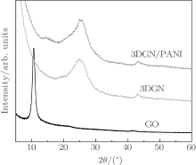
The XRD spectra of GO, 3DGN, and 3DGN/PANI composite are shown in Fig. 3. The peak located at 10.6° is ascribed to the diffraction of the (002) plane for GO. After being reduced to GN hydrogel, the peak of GO disappears and a new broad reflection peak of GN centered at 24.9° is observed in Fig. 3, which could be due to the great reduction of GO.[25] The peaks of 3DGN/PANI composite are similar to those of 3DGN at 25.0° . Based on the work by Gao et al., the pure PANI exhibits four peaks located at 9° , 15.4° , 20.8° , and 25.6° , corresponding to the diffractions of (001), (010), (100), and (110) crystallographic planes of PANI in its emeraldine salt I form.[26] In our case, the peaks for PANI are not apparent, indicating that the PANI in the composite exhibits worse crystallinity than the pure PANI.[27]
 | Fig. 3. XRD patterns of GO, 3DGN, and 3DGN/PANI. |
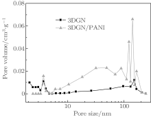
The microstructures of 3DGN and 3DGN/PANI are further investigated by nitrogen adsorption– desorption experiments. The BET surface area of 3DGN/PANI (65.37 m2· g− 1) is much larger than that of 3DGN (37.5 m2· g− 1). The BJH pore size distributions in Fig. 4 indicate that the pores of these materials are composed of mesopores and macropores. The pores of 3DGN/PANI are much more than those of 3DGN with pore sizes of 6 nm∼ 200 nm, and less with pore sizes of 2 nm∼ 3.5 nm.
 | Fig. 4. BJH pore size distributions of 3DGN and 3DGN/PANI. |
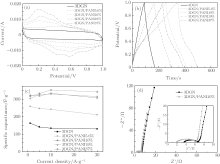
The electrochemical characteristics of the as-prepared 3DGN and 3DGN/PANI are initially investigated using CV, GCD, and EIS measurements under a two-electrode configuration in 1-M H2SO4 electrolyte solution (Fig. 5). The CV curves for the 3DGN and 3DGN/PANI at a scan rate of 20 mV· s− 1 are exhibited in Fig. 5(a). 3DGN/PANI composites with different PANI mass ratios are obtained by using the same 3DGN as the substrate with different ANI concentrations (the ratio of ANI to APS is constant). The CV curve for the 3DGN presents a similar rectangular shape without faradaic current as a result of the electrical double layer capacitive behavior. The behavior of the 3DGN/PANI composite electrode is deviated from the idealized double-layer behavior due to a pair of broad and reversible faradaic surface redox reactions of PANI.
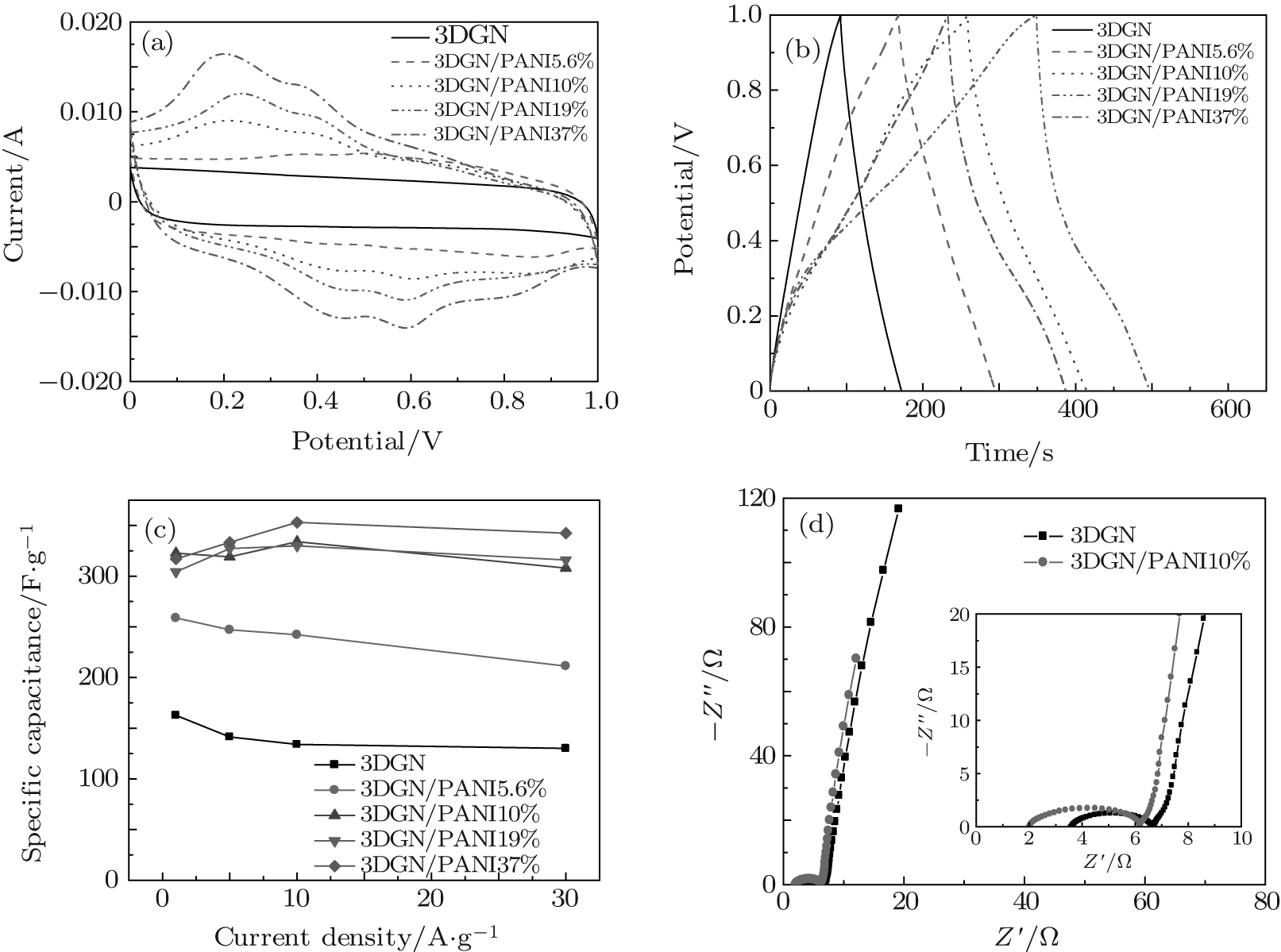 | Fig. 5. (a) CV curves of 3DGN and 3DGN/PANI composites at a scan rate of 20 mV· s− 1. (b) GCD curves of 3DGN and 3DGN/PANI composites at a current density of 1 A· g− 1. (c) The specific capacitances of 3DGN and 3DGN/PANI composites with different PANI contents. (d) Nyquist plots of 3DGN and 3DGN/PANI10% composites and the inset is for the magnified initial range of Nyquist plots. |
The GCD curves from 0 V to 1 V at a current density of 1 A· g− 1 are shown in Fig. 5(b). The pure 3DGN presents a symmetric triangular shape charge/discharge curve, indicating nearly ideal electric double layer capacitive characteristics. While the GCD curves of the 3DGN/PANI composites are deviated from a triangular shape, owing to the redox reactions of PANI. This coincides with the previous results. The specific capacitance (C) of the electrode material is calculated according to the following equation:

where I is the charge/discharge current, Δ t is the discharge time, m is the single electrode weight, and Δ V is the potential drop. Based on the GCD curves and the equation above, the specific capacitances of 3DGN and 3DGN/PANI composites containing 5.6% , 10% , 19% , and 37% of PANI are 162.8 F· g− 1, 258.7 F· g− 1, 322.8 F· g− 1, 304.4 F· g− 1, and 317.1 F· g− 1 respectively at a current density of 1 A· g− 1 (Fig. 5(c)). It is shown that the capacitance of the 3DGN/PANI 10% composite is nearly twice as large as that of the pure 3DGN. The larger capacitance for the 3DGN/PANI composite is attributed to the faradaic pseudocapacitance from PANI. The capacitance of the 3DGN/PANI composite containing more than 10% PANI no longer grows with the increase of the PANI mass ratio. The reason may be that the faradic reaction mainly occurs at the interface between PANI and the electrolyte.[15] The charge has more difficulty transferring across the PANI when its thickness increases, therefore the capacitance contribution of the interior part of PANI is very limited.
Figure 5(c) shows specific capacitance values (measured from GCD curves) for the current density from 1 to 30 A· g− 1. The capacitance of 3DGN is 162.8 F· g− 1 at 1 A· g− 1 and decreases to 130.1 F· g− 1 at 30 A· g− 1 which retains 79.9% . The capacitance of 3DGN/PANI10% composite slightly decreases from 322.8 F· g− 1 at 1 A· g− 1 to 307.9 F· g− 1 at 30 A· g− 1 (maintaining 95.4% ), indicating its excellent rate capability. When the PANI content is more than 10% , the retained capacitance of the composites at 30 A· g− 1 is improved. The slight increase in capacitance may be caused by the increase of the mesopores and macropores in the composites (Fig. 4). In high charging-discharging rates, the composite electrode can achieve highly efficient mass transport through macro/mesopores, resulting in an enhanced rate capability.[2, 28] Moreover, the internal active spots of PANI participate in the redox reaction at the higher current density, therefore the rate capability of the composite is higher than that of the composite with the PANI content.
The Nyquist plots obtained from EIS measurements are exhibited in Fig. 5(d). The curves of 3DGN and the 3DGN/PANI composite (PANI content 10% ) both show the short Warburg curve, suggesting that the ion penetrates into electrode material excellently. We gain the values of equivalent series resistance (ESR) from the x-intercept of the Nyquist plot, obtaining 2.1 Ω for the 3DGN/PANI composite. This value is less than the ESR of 3DGN, i.e., 3.6 Ω , indicating the better rate property.
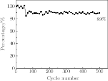
The lifetime stability of 3DGN/PANI composite (3DGN/PANI10% ) is tested using GCD at 30 A· g− 1 for 500 cycles. As shown in Fig. 6, the capacitance is stabilized at a nearly constant value (89% retention), exhibiting good cycling stability. Compared with previous research results, [16– 18] the rate capability of 3DGN/PANI as prepared is much higher, and the cycle stability performances are excellent.
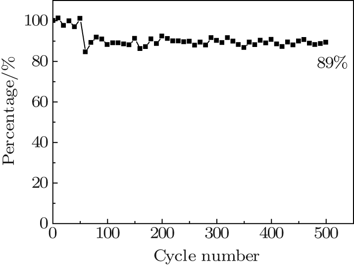 | Fig. 6. Cycle life of 3DGN/PANI composite (3DGN/PANI10% ). |
In this work, 3DGN/PANI composites are prepared through the in situ polymerization on the surface of graphene hydrogel. This method could control the PANI content in composite by the concentrations of ANI and APS solutions. The introduction of the PANI effectively improves the specific capacitance of the electrode material, pure 3DGN, by more than twice. In addition, the 3DGN/PANI composite exhibits high rate capability and good lifetime stability. All the excellent properties are contributed to the synergetic effect of the 3DGN structure and the pseudocapacitance from the PANI.
| 1 |
|
| 2 |
|
| 3 |
|
| 4 |
|
| 5 |
|
| 6 |
|
| 7 |
|
| 8 |
|
| 9 |
|
| 10 |
|
| 11 |
|
| 12 |
|
| 13 |
|
| 14 |
|
| 15 |
|
| 16 |
|
| 17 |
|
| 18 |
|
| 19 |
|
| 20 |
|
| 21 |
|
| 22 |
|
| 23 |
|
| 24 |
|
| 25 |
|
| 26 |
|
| 27 |
|
| 28 |
|