
Sub-Rayleigh limit imaging via intensity correlation measurements*
[Yao Xu-Ria), b) , Li Long-Zhena), b) , Liu Xue-Fenga) , Yu Wen-Kaia), b) , Zhai Guang-Jiea)†  ]
]
]
|
|


†Corresponding author. E-mail: gjzhai@nssc.ac.cn
*Project supported by the National Major Scientific Instruments Development Project of China (Grant No. 2013YQ030595), the Hi-Tech Research and Development Program of China (Grant No. 2011AA120102), and the National Natural Science Foundation of China (Grant No. 11275024).
We demonstrate sub-Rayleigh limit imaging of an object via intensity correlation measurements. The image completely unaffected by the disturbance of diffraction-limit is achieved under the condition that the imaging system has an appropriate field of view. The resolution of this sub-Rayleigh limit imaging system is only tied to the lateral resolution of the illumination light.
In a diffraction-limited system, where the effects due to the diffraction of the light by the boundaries of the pupil become important, a widely used criterion that defines the minimum separation for two points is the Rayleigh limit.[1] Improving the resolution of optical imaging system beyond this diffraction limit is a problem of great interest in both classical and quantum optics. Over the past half century, various methods have been exploited to reach a resolution beyond the Rayleigh limit, such as confocal scanning microscopy, [2] stimulated emission depletion microscopy, [3] scanning near-field optical microscopy, [4] and structured illumination microscopy.[5] Quantum effects[6, 7] have also been used to provide resolution enhancement in principle.
Recently, speckle illumination combined with second-order correlation measurement has been demonstrated to circumvent this Rayleigh limit, [8, 9] in which the amplitude point-spread function (APSF) related to the objective lens is reduced. This protocol is extremely simple to implement, it does not require precision scanning stages, and its lateral resolution can be controlled by adjusting the transverse coherence of the illumination light.
In this paper, we demonstrate that, under the condition that the field of view of the imaging system is larger than a certain extent decided by the object and the pupil of the system, a super-resolution image, which is completely unaffected by the Rayleigh limit of the imaging system, can be reconstructed from intensity correlation measurements. Second-order correlation or other algorithms can be used to retrieve the object. In the intensity correlation sub-Rayleigh protocols mentioned above, [8, 9] although the size of the APSF is reduced, the influence of APSF cannot be eliminated completely and still restricts the system's resolution. In our sub-Rayleigh method, the lateral resolution is only limited by the illumination light and is not affected by the imaging system, which is an enhancement to previous works.
We start from conventional monochromatic imaging, where a circular-pupil thin lens of radius R and focal length f is used. The object distance Do, the image distance Di, and the focal length f obey the Gaussian thin-lens equation

According to the Rayleigh criterion, [1] the resolution limit of this system is determined by the wavelength λ and the NA of the lens

where NA is approximate to R/Do. Assuming incoherent illumination of an object, the linear, space invariant model for a diffraction-limited imaging system becomes[10]

where the impulse response ∣ h(x)∣ 2 is commonly known as the point spread function (PSF), Ig is the ideal geometric irradiance image and ⊗ denotes the convolution symbol. For simplicity, we just consider the case of one transverse dimension. Generalization to two dimensions is possible, but does not add much insight. The PSF which has an extent inversely proportional to the aperture of the lens is

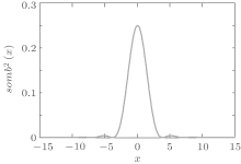
where somb(x) = J1(x)/x and J1(x) is the spherical Bessel function of the first kind. The PSF ∣ h(x)∣ 2, which is also known as the Airy function, has a maximum at x = 0 and is zero over an infinity of circles. As shown in Fig. 1, the oscillation of PSF ∣ h(x)∣ 2 reduces along both positive-x axis and negative-x axis. We make two simplified but reasonable assumptions: (i) ∣ h(x)∣ 2 = 0, ∣ x∣ > X0 where X0 is the third zero of ∣ h(x)∣ 2 and the extent 𝓐 P= [ − X0, X0] is regarded as the effective area of the PSF, (ii) the object is space-limited and vanishes outside the interval x by 𝓐 O = [ − X, X] . If the visual field of the system 𝓐 V is larger than [ − X − X0, X + X0] and the vignetting can be ignored, then under the above assumptions, using straightforward mathematics, we obtain the total intensity on the image plane

Under the condition that the field of view of the system 𝓐 V is larger than [ − X − X0, X + X0] , if the object is irradiated by spatially structured illumination, such as speckle illumination and artificial Bernoulli distribution pattern illumination, then the total intensity on the image plane in the i-th measurement is given by

where 

is the total intensity on the image plane in an ideal imaging system. We investigated the relationship in Eq. (6) through numerical simulation, in which Bernoulli distribution patterns were employed. In the numerical simulation, as shown in Fig. 2(a), the object composed of several stripes was bounded in 𝓐 O = [ − X, X] . As shown in Figs. 2(b) and 2(c), in the circumstances that the 𝓐 V = [ − L, L] was larger than [ − X − X0, X + X0] , the total intensity 


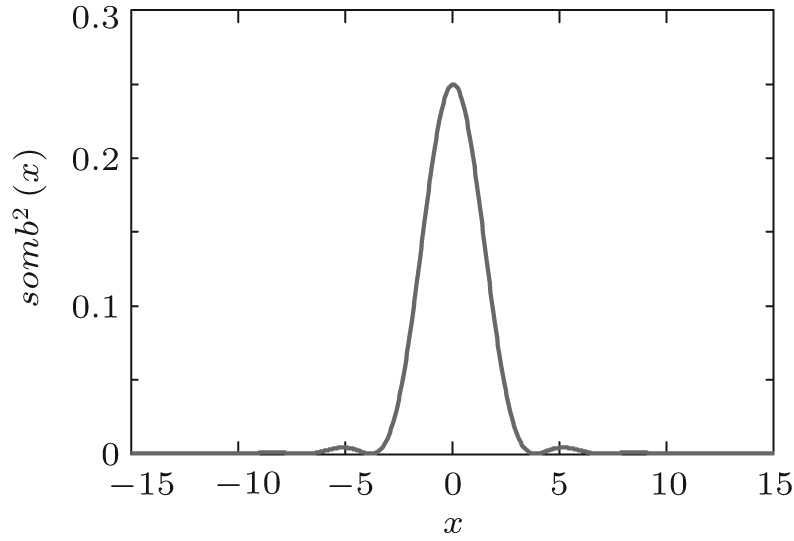 | Fig. 1. The curve of PSF. |
 | Fig. 2. (a) The object. When 𝓐 V = [ − L, L] : (b)      |
It should be noted that, although the high-frequency information has been cut off by the diffraction-limited imaging system, the total intensity on the image plane can be changed just by multiplying a constant. As a result, by employing intensity correlation algorithm which depends on the fluctuations of the total intensity on the object plane, the diffraction-limit in the imaging system can be completely eliminated and the resolution can be controlled by adjusting the transverse coherence of the illumination light. A background-subtracted correlation function, which is used in ghost imaging system[11– 15] and defined as
where ⟨ · · · ⟩ is an average over independent patterns, can be utilized to deduce the object. Other algorithms, such as the compressive sensing (CS), [16, 17] can also be employed to recover the object.
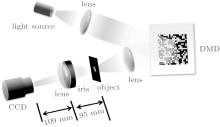
Our experimental setup to demonstrate sub-Rayleigh imaging via intensity correlation measurements is schematically illustrated in Fig. 3. The illumination source was a halogen lamp with center wavelength 550 nm. An area on a digital micromirror device (DMD) in the window of size 1751.04× 1751.04 μ m was combined with a 4-F imaging system (with lens f = 30 mm) to provide Bernoulli distributed random binary patterns on the object plane. The DMD consisted of a 1024× 768 array of individually addressable mirrors and the size of each mirror was 13.68× 13.68 μ m. Each mirror can be turned to two different directions, and the light can be reflected in or out the system accordingly. When mirrors are settled randomly in two directions, a random binary pattern formes on the DMD plane. In the experiment, the random binary pattern was realized by group clusters of 2× 2 mirrors, so the size of one “ pixel” was 27.36× 27.36 μ m. The object to be imaged in transmission was the Group 2, Element 2 portion of the standard U.S. Air Force (USAF) resolution target,
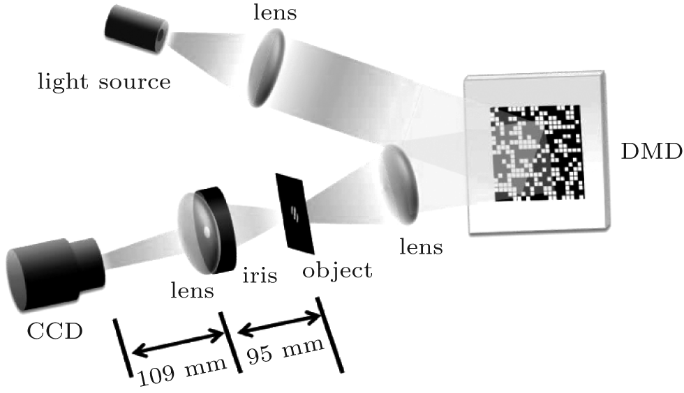 | Fig. 3. Schematic diagram for experimental setup. |
which consisted of three alternating opaque and transparent stripes of width 111 μ m (4.49 line pairs/mm), and a pinhole with aperture of 500 μ m was placed to narrow the object extent. After structured illumination, the object was imaged on the charge-coupled device (CCD) camera by using a diffraction-limited lens (f = 50.8 mm) set in a 300-μ m-diameter iris. The optics provided 0.87× image magnification, and the Rayleigh diffraction bound for the imaging system at the object plane was 212 μ m, which was ∼ 2× larger than the stripe width.
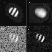
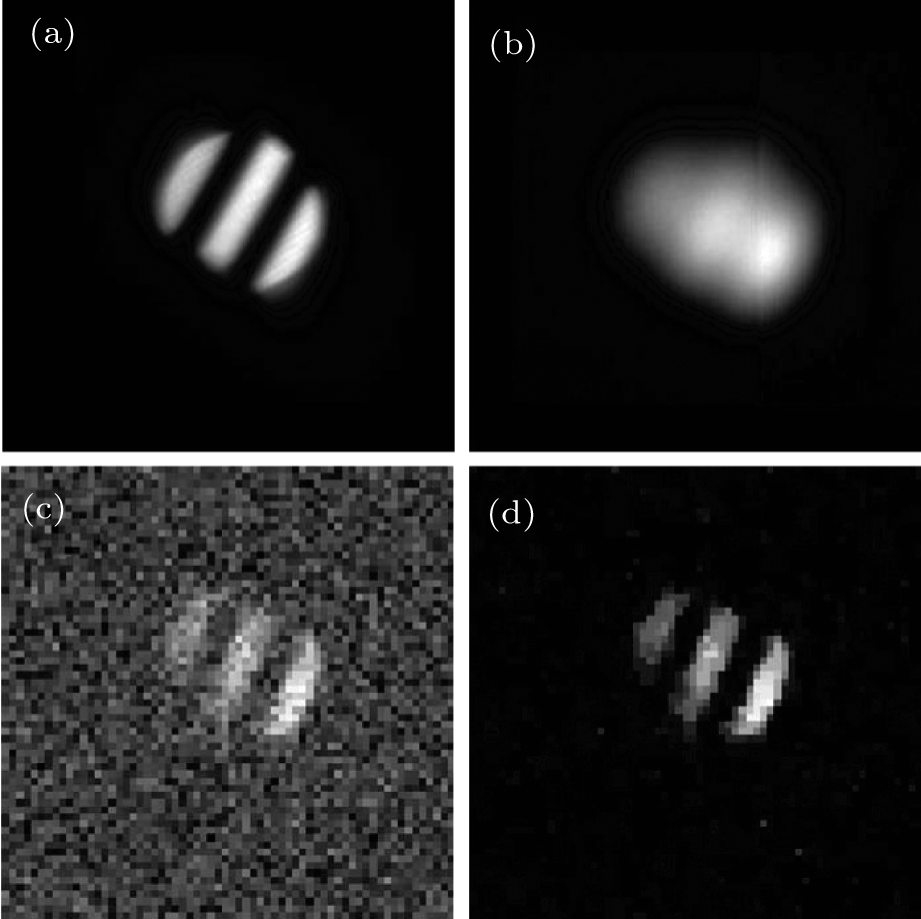 | Fig. 4. (a) Image of the object under conventional illumination without an iris. (b) The diffraction-limited blurred image. (c) Image retrieved by intensity correlation. (d) Image reconstructed by CS. |
The conventional, full-object illumination imaging without an iris is shown in Fig. 4(a). When a 300-μ m-diameter iris is placed at the entrance to the imaging system, the stripes are unresolved, as expected. The blurred image is shown in Fig. 4(b). To implement sub-Rayleigh imaging, 2990 Bernoulli distributed random binary patterns have been imaged on the object in sequence. The second-order correlation measurement as demonstrated in Eq. (7) is used to recover the object information. The three stripes that are lost under conventional illumination in Fig. 4(b) are clearly identifiable, as shown in Fig. 4(c). To achieve a better performance, CS reconstruction algorithm which employs optimization to detect a sparse n-dimensional signal with m < n measurements has been used instead of intensity correlation to reconstruct the object. The goal of CS is to pursue the O′ of the minimum l1-norm in the optimization program:

where 
In conclusion, we have demonstrated a sub-Rayleigh imaging configuration via intensity correlation measurements which can remove the diffraction limit of the imaging lens. The only requirement in our scheme is that the imaging system has a relatively large field of view which is facile to achieve in practical application. Our scheme is not sensitive to the wavelength of the light, need not require precision scanning stages, and is simple to implement. The resolution of our scheme is only subjected to the lateral resolution of the illumination light. Various reconstruction algorithms proposed for intensity measurements can be utilized. Some proposals[21] to obtain subwavelength speckles can be combined with our scheme to reach a higher resolution.
| 1 |
|
| 2 |
|
| 3 |
|
| 4 |
|
| 5 |
|
| 6 |
|
| 7 |
|
| 8 |
|
| 9 |
|
| 10 |
|
| 11 |
|
| 12 |
|
| 13 |
|
| 14 |
|
| 15 |
|
| 16 |
|
| 17 |
|
| 18 |
|
| 19 |
|
| 20 |
|
| 21 |
|