Liu Pei-Liang, Huang Yao, Bian Wu, Shao Hu, Qian Yuan, Guan Hua, Tang Li-Yan, Gao Ke-Lin. Correlation between the magic wavelengths and the polarization direction of the linearly polarized laser in the Ca+ optical clock* . Chinese Physics B, 2015, 24(3): 039501
Permissions
Correlation between the magic wavelengths and the polarization direction of the linearly polarized laser in the Ca+ optical clock*
State Key Laboratory of Magnetic Resonance and Atomic and Molecular Physics, Wuhan Institute of Physics and Mathematics, Chinese Academy of Sciences, Wuhan 430071, China
Key Laboratory of Atomic Frequency Standards, Wuhan Institute of Physics and Mathematics, Chinese Academy of Sciences, Wuhan 430071, China
University of Chinese Academy of Sciences, Beijing 100049, China
*Project supported by the National Basic Research Program of China (Grant No. 2012CB821301), the National Natural Science Foundation of China (Grant Nos. 11474318, 91336211, and 11034009), and the Chinese Academy of Sciences.
Abstract
The magic wavelengths for different Zeeman components are measured based on the40Ca+ optical clock. The dynamic dipole polarizability of a non-zero angular moment level has correlation with the polarization direction of the linearly polarized laser beam, and we show that the four hyperfine structure levels of 4s1/2, m=±1/2 and 3d5/2, m=±1/2 for40Ca+ have the same dynamic dipole polarizability at the magic wavelength and a certain polarization direction. In addition, the existence of a specific direction of polarization may provide a new idea for improving the precision of magic wavelength measurement in experiment.
The magic wavelength is the wavelength at which the polarizability difference for a transition goes to zero; it means that the Stark shifts for the upper and lower levels of the transition are the same.[1– 4] The magic wavelength is interesting[5– 9] due to its importance in a number of applications. Especially, the magic wavelength has extensive applications in quantum state engineering and precision frequency metrology.[10] The investigations of the magic wavelength open a new route to determine the line strength ratio, [11] and the measurements of the ratio of two line strengths can give the accurate transition matrix element, which is important in testing the reliability of models used to interpret atomic parity nonconservation (PNC) studies.[12, 13] For an optical clock, a mageto-optical trap at the magic wavelength[14– 17] can eliminate the ac Stark shift, which decreases the systematic uncertainties. A new generation of atomic clocks based on neutral atoms trapped in the magic-wavelength optical lattices[18– 21] are under development.
The magic wavelength of a transition involving non-zero angular moment states not only connects with the dynamic dipole polarizability, [3, 22– 24] but also depends on the polarization direction of the linearly polarized laser. As for the linearly polarized laser, the dynamic dipole polarizability of the s (with angular moment L = 0) state in the laser field can be written as[25]
where are the absorption oscillator strengths, ω is the laser frequency, and ɛ gi is the excitation energy of the transition.
For the non-zero angular moment states, take the d (with angular moment L = 2) state of Ca+ for example, by using the linearly polarized laser, the dynamic dipole polarizability is given as[26, 27]
where θ p is the angle between the direction of polarization and the quantization z axis, and α d(ω ) and are known as the scalar and the tensor dipole polarizabilities, respectively. When the laser is tuned to the magic wavelength, α s(ω ) should equal α d(ω , θ p), in other words, for the s→ d transiton, the magic wavelength will change with angle θ p. Furthermore, for two different atomic transitions involving four different energy levels, when the polarization of the linearly polarized laser is adjusted to a certain direction, the dynamic dipole polarizabilities of the four energy levels are equal at a certain wavelength, then the magic wavelength for the four states is determined.
In this paper, the magic wavelengths for different Zeeman transitions are measured based on the 40Ca+ optical clock and the correlation between the magic wavelength and the polarization direction of the linearly polarized laser beam is studied. The result shows that two different atomic transitions have the same magic wavelength at a certain polarization direction when the linearly polarized laser is used. Furthermore, a pair of transitions was selected in the previous measurement of magic wavelengths for eliminating the difference caused by the component of the tensor polarizability. If a certain polarization direction of the linearly polarized laser is precisely chosen, the precision of the magic wavelengths can be improved within the same averaging time probing only one Zeeman transition.
2. Experimental measurement
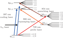
For the 3d state of Ca+ , the two clock transitions corresponding to ❘ m❘ = 1/2, 4s1/2, m= 1/2 → 3d5/2, m= 1/2 and 4s1/2, m= − 1/2 → 3d− 5/2, m= − 1/2, are shown in Fig. 1. According to the definition of the magic wavelength, the dynamic dipole polarizabilities of the two states are equal at the magic wavelength. If the two magic wavelengths are equal, then the dynamic dipole polarizabilities of the four relative states are the same, which will be shown in our expriement.
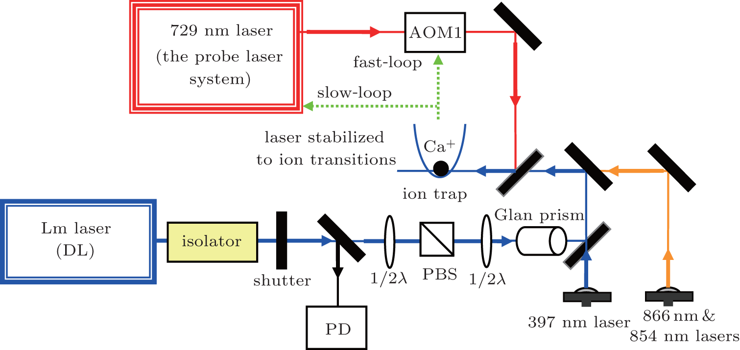
A sketch of the experimental setup for studying the correlation between the magic wavelengths and the direction of the linear polarization of a 395 nm laser (Lm) is shown in Fig. 2. The whole system is composed of two main parts: the first one is an optical clock based on single trapped 40Ca+ , the second one is the Lm laser system for measuring the light shift of the clock transition, in which the direction of polarization of the Lm laser can be precisely adjusted with a λ /2 plate and a Glan prism.
The optical clock system consists of a 729 nm narrow line-width laser, a single ion trapping system, and a closed-loop locking module, which has been described in previous work.[28– 31] The 729 nm laser has a linewidth of less than 5 Hz, and the instability of the laser is 1 × 10− 14 for 20 s. For the ∼ 17 s feedback circle, the error due to the drift of the 729 nm probe laser for one measurement of the light shift of the clock transition can be smaller than 4 Hz, corresponding to ∼ 3 pm of the magic wavelength. The Lm laser is the key element in the measurement of the magic wavelength, so the Lm laser used in the experiment is frequency stabilized using a transfer cavity referenced to the 729 nm probe laser, and the long-term drift is reduced to less than 10 MHz within 4 h. An unpolarized beam splitter (BS) is used to split a part of the beam to a photodiode (PD) for monitoring the power of the Lm laser, which is also shown in Fig. 2. The waist radius of the beam is 203(5) μ m, and the power of the beam is 731(4) μ W. The other parameters of the Lm laser, such as the linear polarization purity and the jitter of the laser power, have been given in the previous paper.[11]
In our experiment, a single 40Ca+ ion is trapped in a miniature Paul trap, and the ion is cooled to a few mK by Doppler cooling. The single ion’ s excess micromotion is minimized with the RF-photon correlation technique.[32] The clock transition splits into ten Zeeman components around the zero-field line center[29] under an additional magnetic field. The magnetic field has an angle of ∼ 40° with the probe laser beam and ∼ 50° with the direction of the probe laser polarization. The probe laser is locked to the clock transition line of Ca+ by feeding back to the frequency of the acousto-optic modulator (AOM1) to compensate for changes from external factors. The pulse sequences of 397 nm, 866 nm, 854 nm, and 729 nm lasers are similar to those used in the 40Ca+ ion optical frequency standard.[29] The pulse sequence of the Lm laser is introduced to measure the light shift of the clock transition. The Lm laser is turned off during the Doppler cooling, and is on and off alternately during the probing stage to measure the light shift. The frequency of AOM1 is recorded automatically in every cycle by a computer, and the light shift caused by the Lm laser beam can be measured by calculating the difference of two cycles with the Lm laser on and off.
The Lm laser beam passes through a λ /2 plate and a Glan prism before going into the ion trap, thus we can adjust the polarization direction of the linearly polarized laser and maintain the purity of the linear polarization. The magic wavelengths for different Zeeman transitions were measured with a fixed polarization direction of the linearly polarized laser before studying the relationship between the magic wavelengths and the direction of the linear polarization. In the experiment, six transition lines were chosen, corresponding to mj= ± 1/2, ± 3/2, ± 5/2 of the 3d5/2 state. For each transition, the light shifts at several different fixed wavelengths around the magic wavelength were measured. The result shows that the light shifts for different atomic transitions at the same wavelength of the Lm laser are different, such as mj = ± 1/2 of 3d5/2 state, and the corresponding magic wavelengths obtained by linearly fitting the light shifts for different transitions are different, as shown in Fig. 3. As to ❘ mj❘ = 3/2, 5/2 of the 3d5/2 state, the same results were obtained.
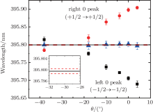
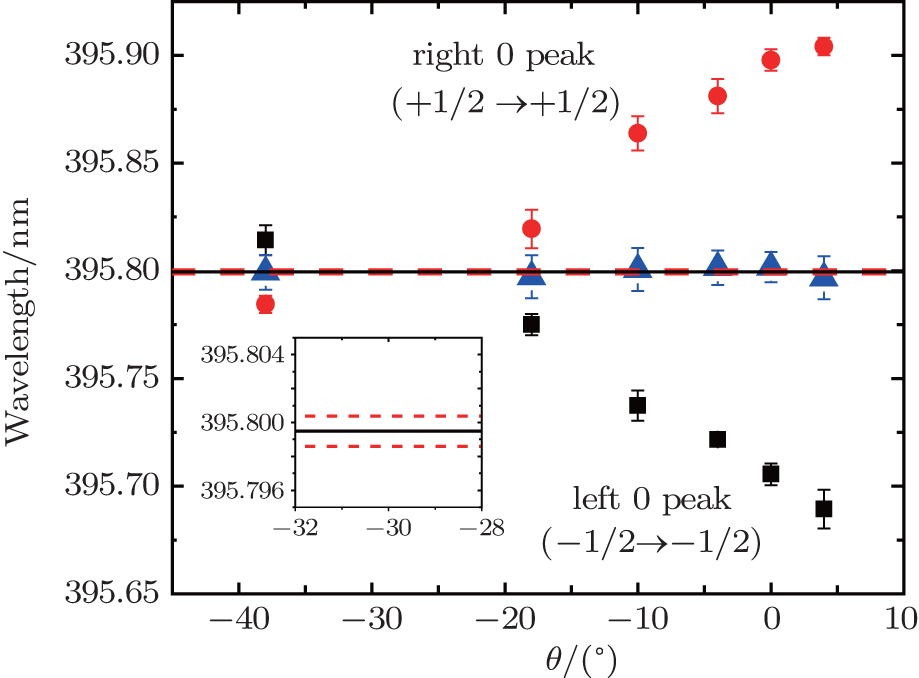
Fig. 3. The relationship between the magic wavelengths of transitions 4s1/2, m= ± 1/2 → 3d5/2, m± 1/2 and angle θ . The θ is the angle between the direction of the linear polarization and the vertical direction. The solid red circles and the solid black blocks represent the measured magic wavelengths at different angles, and the blue triangles are the average values. The errors indicated are the statistical errors of the measurements. The black line in the insert is the average of six blue triangles, and the dashed lines indicate the statistical uncertainty.
Finally, the two atomic transitions corresponding to ❘ mj❘ = 1/2 were chosen to study the correlation between the magic wavelengths and the direction of the linear polarization experimentally. In the experiment, the reference direction is chose as the vertical direction, and θ is the angle between the polarization direction of the Lm laser and the reference direction. In addition, the clockwise direction is defined as positive. Six different angles were chosen in a range of 50° . The magic wavelengths λ mj= 1/2 of clock transition 4s1/2, m= 1/2 → 3d5/2, m= 1/2 and λ mj= − 1/2 of clock transition 4s1/2, m= − 1/2 → 3d− 5/2, m= − 1/2 at each angle were measured respectively, as shown in Fig. 3. The solid red circles indicate the magic wavelengths of clock transition 4s1/2, m= 1/2 → 3d5/2, m= 1/2 at different angles, and the solid black blocks represent those of 4s1/2, m= − 1/2 → 3d− 5/2, m= − 1/2. By analyzing the experimental data, it is found that there is a certain angle θ at which λ mj= 1/2 equals to λ mj= − 1/2. In theory, the two magic wavelengths corresponding to transitions 4s1/2, m= 1/2 → 3d5/2, m= 1/2 and 4s1/2, m= − 1/2 → 3d− 5/2, m= − 1/2 will be equal when θ p is adjusted to a certain value. In other words, the four energy levels of two different transitions have identical dynamic dipole polarizability with certain θ p. The angle θ p has a direct correlation with θ , and θ p will change with θ , so there may be a θ in theory at which λ mj= 1/2 equals to λ mj= − 1/2, which explains our finding.
As shown in Fig. 3, the blue triangles represent the average λ ❘ mj❘ = 1/2 of two magic wavelengths λ mj= 1/2 and λ mj= − 1/2. Here λ ❘ mj❘ = 1/2 is constant with different angles of the linear polarization, it proves that the previous measurement[11] of the magic wavelength is correct. Moreover, we can conclude that if the direction of the linear polarization is controlled precisely and the angle is adjusted to a certain value at which the two magic wavelengths are equal, λ ❘ mj❘ = 1/2 can be obtained by measuring the magic wavelength of a single transition. This means that only one transition peak needs to be locked instead of two in the optical frequency standard, so the measurement precision of the magic wavelengths may be improved compared to the previous measurement.
3. Conclusion
Based on the measurement of magic wavelengths of different transitions corresponding to mj= ± 1/2 of the 3d5/2 state in 40Ca+ , it is shown that the magic wavelengths for different atomic transitions at a fixed polarization direction of the linearly polarized laser are different. For the two clock transitions from the ground state to mj= ± 1/2 of the 3d5/2 state, we preliminary study the correlation between the magic wavelengths and the polarization angle of the linearly polarized laser. After the measurement of the magic wavelengths at different polarization directions of the linearly polarized laser, an angle at which the two magic wavelengths are equal is determined; there the four relevant states have equal dynamic dipole polarizability. In addition, the determination of the angle could give an innovative idea for improvement on the measurement precision of magic wavelengths and the measurement scheme is also suitable for ❘ mj❘ = 3/2, 5/2 of the 3d5/2 state.
Acknowledgments
We gratefully acknowledge Shi T and Li C for their valuable suggestions. We also thank Huang X, Shu H, Fan H, Guo B, Liu Q, Qu W, Cao J and Ou B for the early experiments.
BarberZ W, StalnakerJ E, LemkeN D, PoliN, OatesC W, FortierT M, DiddamsS A, HollbergL, HoytC W, TaichenachevA V and YudinV I2008Phys. Rev. Lett. 100103002DOI:10.1103/PhysRevLett.100.103002[Cited within:1][JCR: 7.943]
TakamotoM, KatoriH, MarmoS I, OvsiannikovV D and PalćhikovV G2009Phys. Rev. Lett. 102063002DOI:10.1103/PhysRevLett.102.063002[Cited within:1][JCR: 7.943]
16
LudlowA D, ZelevinskyT, CampbellG K, BlattS, BoydM M, de Mirand aM H G, MartinM J, ThomsenJ W, ForemanS M, YeJ, FortierT M, StalnakerJ E, DiddamsS A, Le CoqY, BarberZ W, PoliN, LemkeN D, BeckK M and OatesC W2008Science3191805DOI:10.1126/science.1153341[Cited within:1]
17
ParkC Y, ParkH Y, YuD H, LeeW K, ParkS E, KimE B, LeeS K, ChoJ W, YoonT H, MunJ, ParkS J, KwonT Y and LeeS B2013Metrologia50119DOI:10.1088/0026-1394/50/2/119[Cited within:1][JCR: 1.902]
... The magic wavelength of a transition involving non-zero angular moment states not only connects with the dynamic dipole polarizability,[3,22#cod#x2013 ...
1
2010
3.607
0.0
... 4] The magic wavelength is interesting[5#cod#x2013 ...
1
2014
3.042
0.0
... 4] The magic wavelength is interesting[5#cod#x2013 ...
1
2013
3.042
0.0
1
2013
3.042
0.0
1
2010
3.042
0.0
1
2011
0.811
0.4541
... 9] due to its importance in a number of applications ...
1
2008
0.0
0.0
... [10] The investigations of the magic wavelength open a new route to determine the line strength ratio,[11] and the measurements of the ratio of two line strengths can give the accurate transition matrix element, which is important in testing the reliability of models used to interpret atomic parity nonconservation (PNC) studies ...
3
2014
0.0
0.0
... [10] The investigations of the magic wavelength open a new route to determine the line strength ratio,[11] and the measurements of the ratio of two line strengths can give the accurate transition matrix element, which is important in testing the reliability of models used to interpret atomic parity nonconservation (PNC) studies ...
... [11] ...
... 1/2 is constant with different angles of the linear polarization, it proves that the previous measurement[11] of the magic wavelength is correct ...
1
2013
3.042
0.0
... [12,13] For an optical clock, a mageto-optical trap at the magic wavelength[14#cod#x2013 ...
1
2009
3.042
0.0
... [12,13] For an optical clock, a mageto-optical trap at the magic wavelength[14#cod#x2013 ...
Based on the binary Bell polynomials, the bilinear representation, bilinear Bäcklund transformation and the Lax pair for the dissipative (2+1)-dimensional Ablowitz–Kaup–Newell–Segur (AKNS) equation are obtained. Moreover, the infinite conservation laws are also derived.
1 Business School, Shandong University of Political Science and Law, Jinan 250014 2 School of Mathematical Sciences, Liaocheng University, Liaocheng 252059
... [12,13] For an optical clock, a mageto-optical trap at the magic wavelength[14#cod#x2013 ...
We measured the absolute frequency of the optical clock transition S-1(0)(F = 1/2)-P-3(0)(F = 1/2) of Yb-171 atoms confined in a one-dimensional optical lattice and it was determined to be 518 295 836 590 863.5(8.1) Hz. The frequency was measured against Terrestrial Time (TT; the SI second on the geoid) using an optical frequency comb of which the frequency was phase-locked to an H-maser as a flywheel oscillator traceable to TT. The magic wavelength was also measured as 394 798.48(79) GHz. The results are in good agreement with two previous measurements of other institutes within the specified uncertainty of this work.
Park, Chang Yong 1 ;Yu, Dai-Hyuk 1 ;Lee, Won-Kyu 1 ;Park, Sang Eon 1 ;Kim, Eok Bong 1 ;Lee, Sun Kyung 1 ;Cho, Jun Woo 1 ;Yoon, Tai Hyun 1 ;Mun, Jongchul 1 ;Park, Sung Jong 1 ;Kwon, Taeg Yong 1 ;Lee, Sang-Bum 1 ;
... 17] can eliminate the ac Stark shift, which decreases the systematic uncertainties ...
1
2005
38.597
0.0
... A new generation of atomic clocks based on neutral atoms trapped in the magic-wavelength optical lattices[18#cod#x2013 ...
1
2014
38.597
0.0
1
2009
3.607
0.0
1
2013
0.0
0.0
... 21] are under development ...
1
2014
3.042
0.0
... The magic wavelength of a transition involving non-zero angular moment states not only connects with the dynamic dipole polarizability,[3,22#cod#x2013 ...
1
2012
3.042
0.0
1
2010
3.607
0.0
... 24] but also depends on the polarization direction of the linearly polarized laser ...
1
2013
3.042
0.0
... 0) state in the laser field can be written as[25] ...
1
2012
3.042
0.0
... for example, by using the linearly polarized laser, the dynamic dipole polarizability is given as[26,27] ...
1
2014
3.042
0.0
... for example, by using the linearly polarized laser, the dynamic dipole polarizability is given as[26,27] ...
Taking into account the energy and angular momentum transferred from a rotating black hole (BH) to the inner accretion disk by the magnetic connection (MC) process, we simulate the x-ray spectra from the disk-corona system with two different magnetic configurations using the Monte Carlo method. The results show that the MC process reduces the ratio of the power dissipated in the corona to the total and softens the spectrum. The influence of the MC process is stronger with a higher BH spin, a larger accretion rate, and a larger and more centralized magnetic flux threading the disk. The comparison of the model spectra with the observational data suggests that large-scale magnetic fields accumulating in the inner disk could be a candidate explanation for the hard-to-soft state evolutions in BH binaries.
1 School of Physics and Optoelectronic Engineering, Yangtze University, Jingzhou 434023 2 School of Physics, Huazhong University of Science and Technology, Wuhan 430074
... [28#cod#x2013 ...
2
2012
3.042
0.0
... [32] The clock transition splits into ten Zeeman components around the zero-field line center[29] under an additional magnetic field ...
... [29] The pulse sequence of the Lm laser is introduced to measure the light shift of the clock transition ...
1
2011
3.042
0.0
1
2011
1.438
0.0
... 31] The 729#cod#x00A0 ...
1
1998
0.71
0.0
... [32] The clock transition splits into ten Zeeman components around the zero-field line center[29] under an additional magnetic field ...
Correlation between the magic wavelengths and the polarization direction of the linearly polarized laser in the Ca+ optical clock*


 ]
]