


Fabrication and magnetocrystalline anisotropy of NiCo(002) films*
[Fan Wei-Jia, Ma Li, Shi Zhong, Zhou Shi-Ming† ]
]
]
|
|


†Corresponding author. E-mail: shiming@tongji.edu.cn
Project supported by the National Natural Science Foundation of China (Grant Nos. 11374227, 51331004, 51171129, and 51201114) and the Shanghai Science and Technology Committee, China (Grant Nos. 0252nm004, 13XD1403700, and 13520722700).
A series of 30-nm-thick epitaxial Ni xCo1- x (002) alloy films are fabricated by DC magnetron sputtering. MgO (002) and SrTiO3 (002) single substrates are used for x>0.5 and x<0.5, respectively. The magnetocrystalline anisotropy of Ni xCo1- x (002) alloy films is studied in the entire composition region for 0≤ x≤ 1.0. When x decreases, the cubic magnetic anisotropy constant K1 changes sign from negative to positive at x=0.96 and becomes negative again at x= 0.79. It becomes more negative as x decreases from 0.79 to 0. The uniaxial anisotropy K u is smaller than the K1 by a factor of two orders.
Magnetic anisotropy of magnetic materials has always been a subject of interest in condensed matter physics. As is well known, magnetocrystalline anisotropy (MCA) arises from both the spin– orbit coupling (SOC) and the exchange split.[1] Within the frame of the perturbation theory, the magnetic anisotropy constant may be proportional to the SOC strength ξ 2 and ξ 4 for uniaxial anisotropy and cubic anisotropy, respectively.[1] For L1(0) FePtPd ternary alloys, [2, 3] for example, the perpendicular magnetic anisotropy is found to be proportional to ξ 1.5. More remarkably, the MCA of transition metallic alloys is also found to strongly depend on the numbers of 3d electrons in the valence band.[4– 6] For bulk centered cubic (BCC) NiFe alloys, the cubic magnetic anisotropy constant K1 approaches zero near Ni0.8Fe0.2 due to the band-filling effect of 3d band, although K1 is positive for BCC Ni and Fe.[10]
The MCA of 3d magnetic alloys has been studied extensively.[7– 12] For bulk Ni-rich NiFe alloys with face centered cubic (FCC) structure, the sign change is located near the composition of Ni0.8Fe0.2.[8] In contrast, the composition dependence of the MCA of bulk NixCo1-x (= NiCo) is rather complicated, [7, 9] compared with that of NiFe alloys. For the bulk Ni-rich NiCo alloys with FCC structure, the K1 changes the sign from negative to positive at 4 at.% Co and then once again turns negative near 20 at.% Co.[7] Furthermore, the MCA of FCC Co-rich NiCo alloys has seldom been studied despite its crucial importance. This is partly because bulk Co-rich NiCo alloys at the equilibrium state are of hexagonal close-packed (HCP) structure instead of the FCC structure. Fortunately, the epitaxial FCC Co films and Co-rich NiCo films have very recently been fabricated on single crystal substrates by molecular beam epitaxy or magnetron sputtering.[13] Therefore, we are allowed to study the MCA of NixCo1-x alloys within the entire composition region. In this work, we have successfully fabricated a series of epitaxial FCC NixCo1-x (002) alloy films with 0 ≤ x≤ 1.0, and then studied the MCA by the magnetic torque technique. It is found that the K1 of the Ni-rich NixCo1-x (002) films exhibits a similar variation trend for Ni-rich NiCo bulk alloys. For Co-rich NiCo epitaxial films, the K1 is negative and its magnitude increases with decreasing x.
NixCo1-x thin films were fabricated on MgO (002) single crystalline substrates for x> 0.5 and on SrTiO3 (002) single crystalline substrates for x< 0.5 in a high vacuum DC magnetron sputtering system. Here, SrTiO3 substrates favor fabrication of the epitaxial Co-rich NiCo films.[14] The samples were deposited from NiCo alloy targets, which were formed by adding Co/Ni small pieces on Ni/Co targets. The base pressure was 1× 10⁻⁵ Pa and the working Ar pressure was 0.35 Pa. The deposition rate of NixCo1-x films was about 0.1 nm/s. The MgO and SrTiO3 substrates were first annealed at 500 ° C and 650 ° C for one hour to annihilate possible contamination on the surface, respectively. The temperatures of MgO and SrTiO3 substrates were then kept at 300 ° C and 500 ° C during deposition of Ni-rich and Co-rich NiCo films, respectively, and post-annealing was performed at the same temperature for two hours. The microstructure and thickness of films were characterized by x-ray diffraction (XRD) and x-ray reflectivity (XRR) by a Bruker D8 diffractometer with 5-axis configuration and Cu Kα (λ = 0.1542 nm), respectively. The epitaxial growth was proven by the x-ray pole figures. The alloy composition was characterized by energy dispersive x-ray spectroscopy (EDX) in combination with scanning electronic microscopy (SEM). In-plane magnetization hysteresis loops and magnetic torque curves were measured by a vector vibrating sample magnetometer (VVSM) of Lakeshore 7407. Components of the magnetization parallel and perpendicular to the external magnetic field H, Mx, and My, were measured simultaneously. In the presence of an in-plane H, Mx, and My were both parallel to the film plane. Here, the curve of Mx versus H corresponds to the conventional magnetization hysteresis loop. In magnetic torque measurements, My was measured as a function of the orientation of the sample under a fixed H and the magnetic torque, i.e., the product of the My and H, was obtained. All of the measurements were performed at room temperature.
The film thickness characterized by XRR is 30± 1.0 nm. Figures 1(a) and 1(b) present the typical XRD spectra of Co-rich and Ni-rich NiCo films, respectively. For Co-rich NiCo films on SrTiO3 (002) substrates in Fig. 1(a), two peaks near 2θ = 46° and 52° , correspond to SrTiO3 (002) and NixCo1-x (002) orientations, [13] respectively. For Ni-rich NiCo films on MgO substrates in Fig. 1(b), two peaks are found at 2θ = 42° and 52° , which refer to MgO (002) and NixCo1-x (002) orientations, respectively. The XRD peak of the NixCo1-x(002) almost does not shift with x and the lattice constant of NixCo1-x films along the film normal direction is about 0.3524 nm for all samples, which is close to their bulk value.[15] This happens because the strain of epitaxial films is relaxed when the film thickness is larger than a critical value. It is noted that there is no diffraction peak near 2θ = 75° for HCP (11
Figures 2(a)– 2(f) show typical hysteresis loops of Co film and Ni0.8Co0.2 film (x= 0.8) along [200], 
 | Fig. 1. XRD spectra of Co-rich NiCo films on SrTiO3 substrates (a) and Ni-rich NiCo films on MgO substrates (b), ϕ scanning at 2θ = 44.36° for the Co film and 39.98° for the SrTiO3 substrate (c). |
 | Fig. 2. Typical in-plane hysteresis loops of the Co (left column) and Ni80Co20 (right column) films for H along the [200] ((a) and (d)), [√ 310] ((b) and (e)), [220] ((c) and (f)). |
To get the K1 and Ku, magnetic torque curves were measured for the NixCo1-x films. Figure 4(a)shows typical torque curves for Co, Ni0.8Co0.2, and Ni films. All three samples have four-fold symmetry. The magnetic torque changes similarly for Co and Ni films, whereas it varies in an opposite way for the Ni0.8Co0.2 films. Moreover, the Co film has the largest magnitude in the torque curve and the Ni0.8Co0.2 film has the smallest one, indicating the effect of the alloy composition on the magnetic anisotropy constants.
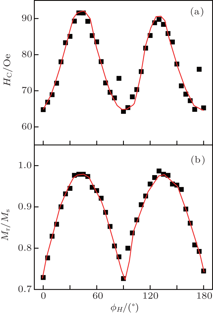 | Fig. 3. For the Ni film, the coercivity (a) and remanent ratio (b) as a function of the orientation of the external magnetic field. Solid lines serve a guide to the eye. Here, ϕ H= 0 for H along the [200]. |
 | Fig. 4. (a) Torque as a function of the angle difference between the external magnetic field and the magnetization vector, and (b) the spontaneous magnetization Ms versus the x. The solid lines refer to the fitted results in panel (a) and serve a guide to the eye in panel (b). In panel (a), H= 200 Oe for x= 0.80, and H= 1.0 kOe for x= 0 and 1.0. |
The magnetic torque curves can be fitted as follows. The free energy of the NixCo1-x films includes the MCA, uniaxial anisotropy, and the Zeeman energy, and it reads as follows:
where ϕ and ϕ H are the angles of the magnetization vector and the external magnetic field with respect to [200]. At a specific orientation of the external magnetic field, the equilibrium angular position can be obtained from the equation ∂ E/∂ ϕ = 0. Accordingly, the magnetic torque can be calculated by the following equation, L= MsH sin(ϕ -ϕ H). Since the magnetic torque curves can be fitted very well in Fig. 4(a) the K1 and Ku can be deduced. For the Co (002) films, the K1= -7.6× 10⁵ erg/cm3. In the above fitting process, the saturation magnetization Ms at room temperature is shown in Fig. 4(b). The Ms decreases from 1330 emu/cm3 for Co to 493 emu/cm3 for Ni, which is in agreement with the Slater– Pauling curve.[16] The value of Ms for the FCC Co film is also close to the reported results from other research groups.[17– 21]
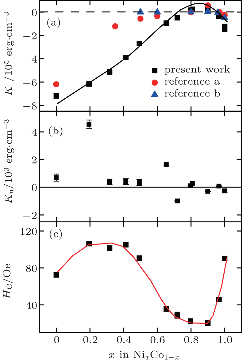
Figure 5(a) shows that with increasing x, K1 increases from negative to positive values at x= 0.79, and then turns negative again. In the region from x= 0.79 to 1.0, the values of the K1 for the present films are close to other reported results.[7] For 0.35< x< 0.7, however, the K1 for the present NixCo1-x films is larger than the results given by other research groups.[17, 22] It is noted that the K1 of the present Ni film is smaller than that of 5.6× 10⁵ erg/cm3 for bulk FCC Ni.[9] The discrepancy of the K1 may arise from the different lattice constants.[18, 19, 23– 25] For the present epitaxial NixCo1-x films, the lattice constant along the film normal direction is 0.352 nm for all x whereas for bulk FCC-NiCo crystals, the lattice constant changes from 0.354 to 0.352 nm for x from 0 to 1.0.[15] For the present epitaxial Co films, the lattice constant c is reduced by 0.45% when compared with the bulk FCC Co.
For the present NixCo1-x films, the non-monotonic change of the K1 is in agreement with the theoretical prediction.[11, 26] The ab initio calculations show that the orbital moment and the magnetostriction coefficient of NiCo alloys change non-monotonically with the alloy composition due to the band-filling effect.[26] The effective SOC strength and the MCA are expected to have similar variation trends. Therefore, the non-monotonic variation of the K1 in Fig. 5(a) can be explained in terms of the band-filling effect. It is noted that in the NixCo1-x (002) films, the second order of the MCA K2 cannot be obtained from the magnetic torque measurements. As shown in Fig. 5(b), the Ku is smaller than the K1 by a factor of two orders and the data are much more scattered.
It is interesting to analyze the composition depedence of the in-plane coercivity along the easy axis. Figure 5(c) shows that the in-plane coercivity has a minimum near x= 0.90 because the magnetization reversal mechanism of NixCo1-x films is mainly determined by the MCA and the NixCo1-x (002) films near x= 0.9 are soft magnetic materials due to small K1. Moreover, for most of the epitaxial NixCo1-x (002) films the coercivity is smaller than the anisotropic field, indicating the multidomain magnetization reversal process. For example, the coercivity and the anisotropic field are 76 and 123 Oe for the Co film, respectively. Finally, the interfacial morphology should also be considered. For example, Lukaszew et al. have found the coercivity of the Ni films on the MgO substrate is 200 Oe, [27] which is much larger than that (90 Oe) of the present Ni film, this was attributed to the exchange bias induced by an ultrathin NiO layer at the Ni/MgO interface. For the present Ni film, a clean Ni/MgO interface is therefore obtained without any NiO ultrathin layer at the interface.[28]
In summary, we have fabricated 30-nm-thick epitaxial NixCo1-x films on MgO(002) substrates for x> 0.5 and on SiTiO3 substrates for x< 0.5. The K1 increases from negative to positive with a crossover near x= 0.79 when x changes from 0 to 0.90. As x further increases, the K1 decreases from positive to negative with a crossover near x= 0.95. For the NixCo1-x films x> 0.35, the composition dependence of the K1 reproduces the results of bulk NiCo alloys. The in-plane coercivity also changes non-monotonically with x, exhibiting a minimal value near x= 0.90. These results will be helpful to understand the MCA of 3d transition metals and alloys.
| 1 |
|
| 2 |
|
| 3 |
|
| 4 |
|
| 5 |
|
| 6 |
|
| 7 |
|
| 8 |
|
| 9 |
|
| 10 |
|
| 11 |
|
| 12 |
|
| 13 |
|
| 14 |
|
| 15 |
|
| 16 |
|
| 17 |
|
| 18 |
|
| 19 |
|
| 20 |
|
| 21 |
|
| 22 |
|
| 23 |
|
| 24 |
|
| 25 |
|
| 26 |
|
| 27 |
|
| 28 |
|