


Flexural wave band-gaps in phononic metamaterial beam with hybrid shunting circuits*
[Zhang Hao, Wen Ji-Hong† , Chen Sheng-Bing, Wang Gang, Wen Xi-Sen]
, Chen Sheng-Bing, Wang Gang, Wen Xi-Sen]
|
|


†Corresponding author. E-mail: wenjihong nudt1@vip.sina.com
*Project supported by the National Natural Science Foundation of China (Grant Nos. 51275519 and 51175501).
Periodic arrays of hybrid-shunted piezoelectric patches are used to control the band-gaps of phononic metamaterial beams. Passive resistive-inductive (RL) shunting circuits can produce a narrow resonant band-gap (RG), and active negative capacitive (NC) shunting circuits can broaden the Bragg band-gaps (BGs). In this article, active NC shunting circuits and passive resonant RL shunting circuits are connected to the same piezoelectric patches in parallel, which are usually called hybrid shunting circuits, to control the location and the extent of the band-gaps. A super-wide coupled band-gap is generated when the coupling between RG and the BG occurs. The attenuation constant of the infinite periodic structure is predicted by the transfer matrix method, which is compared with the vibration transmittance of a finite periodic structure calculated by the finite element method. Numerical results show that the hybrid-shunting circuits can make the band-gaps wider by appropriately selecting the inductances, negative capacitances, and resistances.
Over the past decade phononic crystals/metamaterials, which are a kind of artificial composite material with structural periodicities, have emerged as a valid technique for structural vibration attenuation.[1– 21] Phononic crystals/metamaterials exhibit the phenomenon and characteristic of band-gaps, in which the propagation of elastic or acoustic waves is forbidden.
However, for traditional phononic crystals/metamaterials, the location and the extent of the band-gaps are untunable if the components and configurations are given. In order to overcome this intrinsic frequency limitation, a lot of effort has been made to design intelligent phononic crystals/metamaterials whose band-gaps are tunable.[22– 32] These researches show that periodic arrays of shunted piezoelectric patches may be a promising way to achieve intelligent phononic metamaterials.
The piezoelectric shunting technique was originally proposed by Forward, [33] and further investigated by Hagood and Von Flotow, [34] who developed the first analytical formulation for both resistive (R) and resistive/inductive (RL) shunts to demonstrate how the equivalent material properties of a piezoelectric patch are changed by passive shunting networks. The idea of using periodic arrays of piezoelectric shunts to construct phononic metamaterials was first proposed by Thorp et al. about ten years ago.[21] Subsequently, a growing interest for investigating the propagation of elastic waves in periodic structures with arrays of piezoelectric shunts has been witnessed.[23, 24, 28, 30– 32] Yet, the resonant band-gaps (RGs) produced in phononic metamaterials with passive shunts are usually very narrow. To achieve broad band-gaps, phononic metamaterials with multi-branch passive shunts connected to each piezoelectric patch have been investigated.[25] More recently, the active negative capacitive (NC) shunting technique was found to be a simple but effective method to broaden the Bragg band-gaps (BGs). Chen developed an analytical model of the phononic metamaterial beam with arrays of NC piezoelectric shunts.[26] Casadei et al. investigated a cantilever plate with arrays of active NC shunting circuits and passive resonant RL shunting circuits.[29] These NC shunts and RL shunts are connected to different piezoelectric patches. Their work showed that the band-gaps produced in the cantilever plate can be broadened.
In this paper, we consider an alternative approach to broaden the band-gaps of the phononic metamaterial beam based on periodic arrays of hybrid-shunted piezoelectric patches, within which the active NC shunting circuits and passive resonant RL shunting circuits are connected to the same piezoelectric patches in parallel. The coupling of RG and BG is also studied. This study shows that a super-wide band-gap can be achieved when the coupling between RG and BG occurs, which is very significant to the practical applications of sound and structural vibration attenuation in engineering. In this paper, the attenuation constant of the infinite periodic structure is predicted by the transfer matrix (TM) method, which is compared with the vibration transmittance of a finite periodic structure calculated with the finite element (FE) method. Our numerical results show that hybrid-shunting circuits can make the band-gaps wider by appropriately selecting the values of inductances, negative capacitances, and resistances.
This paper is organized as follows. In Section 2, models of the phononic metamaterial beam and methods for the band-gap calculation are presented. Section 3 is devoted to the description of the band-gap characteristics. Some interesting phenomena are demonstrated and discussed. Especially, a super-wide gap is achieved due to the coupling between resonance and Bragg gaps. Finally, Section 4 concludes this paper.
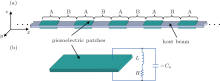
As shown in Fig. 1(a), shunted piezoelectric patches are periodically stuck to the surfaces of a host beam in pairs in order to form a one-dimensional phononic metamaterial. The parts with the piezoelectric patches are denoted as A, while the other parts are denoted as B. In the hybrid-shunting circuits, active NC shunts and passive RL shunts are connected to the same piezoelectric patch in parallel, as illustrated in Fig. 1(b).
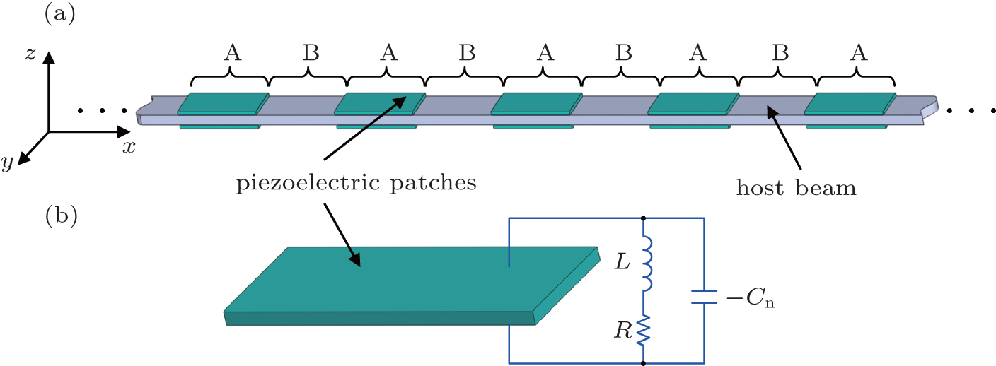 | Fig. 1. (a) Phononic metamaterial beam; (b) piezoelectric patch with hybrid shunts. |
The electropolar surfaces of the piezoelectric patches are perpendicular to the z axis, and all of the surfaces of the patches are free of constraint, except those in the direction along the x axis. Therefore, the constitutive equation of the piezoelectric patches can be expressed as

where 1, 2, and 3 denote x, y, and z coordinates, respectively, S1 and T1 are the normal strain and the normal stress along the x axis, respectively, D3 is the electric displacement on the electrodes, E3 is the electric field in the patch, 

The impedance Z of the shunting circuit connecting to each PZT patch can then be written as

where s = iω is the Laplace operator, and L, − Cn, and R are the inductances, the negative capacitances, and the resistances, respectively. The electric current generated by each piezoelectric patch can be written as

where hp is the thickness of the piezoelectric patch, and As is the area of the piezoelectric electrode. By applying Eq. (3) in Eq. (1), we obtain

where Cp is the inherent capacitance of the piezoelectric patch at constant stress, which can be expressed as

When the harmonic vibration is assumed, the equivalent elastic modulus of each shunting piezoelectric patch can be written as
Equation (6) indicates that the equivalent elastic modulus of each shunting piezoelectric patch varies with L, − Cn, and R, this leads to the tunability of the band-gaps.
If each segment A or B of the beam can be considered under the Euler– Bernoulli condition, then the governing differential equations of transverse vibration can be expressed as

where Φ (x, t) is the displacement of the beam along the z axis, and EI, ρ , and A are the bending rigidity, the density, and the cross-section area of the beam, respectively.
Therefore, by using the transfer matrix method[23, 24, 32] and the Bloch theorem for infinitely periodic boundary conditions, equation (7) can be transformed into an eigenvalue equation

where k is the wave number depending on frequency ω , and a is the lattice constant of the phononic metamaterial beam.
For a given frequency ω , we can calculate the wave number k by using Eq. (8). If k is a real number, then the wave can propagate through the phononic metamaterial beam, indicating that the frequency is in a pass band. In contrast, if k is a complex number, then the wave will be attenuated in the phononic metamaterial beam, indicating that the frequency is in a band-gap. The attenuation constant μ , i.e., the product of the imaginary part of k and lattice constant a, indicates the attenuation of the amplitude when the elastic or acoustic wave propagates from one period to the next.
To verify the band-gaps predicted by the TM method, a coupled piezo-circuit-structural model of a finite structure with eight unit cells is built by using the well-known FE software: COMSOL Multiphysics, as illustrated in Fig. 2. Free boundary conditions are used on both ends of the beam. A displacement excitation varying harmonically in time is set on the left side of the phononic metamaterial beam, and it is along the z axis. The amplitude of the displacement excitation (W1) is 1 × 10− 3 m. To obtain the vibration transmittance TN, the frequency response amplitude W2 on the other side of the phononic metamaterial beam is calculated. Therefore, TN of the phononic metamaterial beam can be obtained as

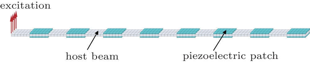 | Fig. 2. FE model of a phononic metamaterial beam. |
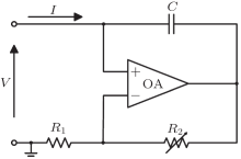
Negative capacitance was first introduced by Forward.[36] Subsequently, it received much attention in noise and vibration control.[37, 38] Although negative capacitance does not exist as a passive electric component, it can be generated by the active synthetic circuit shown in Fig. 3. This circuit consists of a capacitor, two resistors, and an operational amplifier. The equivalent negative capacitance of this synthetic circuit can be expressed as

To obtain the negative capacitances mentioned in the previous section, the electric components in Fig. 3 should be appropriately chosen. In general, negative capacitances of different values can be easily achieved by simply varying one resistor of the active synthetic circuit.
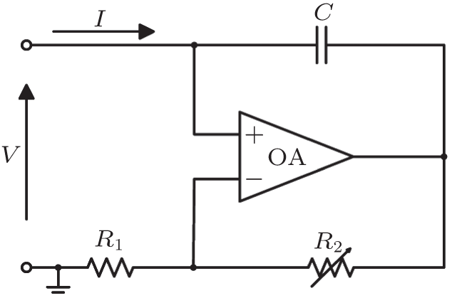 | Fig. 3. Synthetic negative capacitance circuit. |
In order to validate the theoretical analysis and estimate the capability of periodic passive RL shunts and active NC shunts to generate wider band-gaps and larger attenuations, a phononic metamaterial beam consisting of an epoxy host and PZT-5H patches is chosen to calculate the attenuation constant of the infinite periodic structure and the vibration transmittance of the finite periodic structure. The geometric parameters and material properties employed in the calculations are listed in Tables 1 and 2.
| Table 1. Geometric parameters and material properties of the host beam. |
| Table 2. Geometric parameters and material properties of the PZT-5H patch. |
In this subsection, as an illustrative example, the inductances, negative capacitances, and resistances are chosen as L = 1.2 H, − Cn = − 0.6Cp, and R = 100 Ω .
Figures 4(a) and 4(b) illustrate the calculated attenuation constants and vibration transmittances of the phononic metamaterial beam with different configurations of the shunting circuits. For comparison, the short circuit case (the thin solid line) is also provided as a baseline reference, in which the piezoelectric patches are not connected to the shunting circuits. The closed RL (the dotted line) only case and the closed NC only case (the thick dashed line) show the effects of the passive RL shunts and the active NC shunts on the band-gaps, respectively. In the closed RL + NC case (the thick solid line), both the passive RL shunting circuit and the active NC shunting circuit are connected to each piezoelectric patch in parallel.
 | Fig. 4. (a) Attenuation constant of infinite periodic structure obtained by the TM method. (b) Vibration transmittance of finite periodic structure obtained by the FE method. |
Figure 4(a) shows the attenuation constants of the infinite periodic structure calculated with the TM method. It can be seen that two BGs are achieved in the short circuit case, which can be ascribed to the impedance mismatch between parts A and B. In the closed RL only case, a narrow RG (about 390– 470 Hz) is achieved as a result of the internal resonances of the passive resonant shunts. The closed NC only case illustrates that the active NC shunting circuits can broaden the two BGs. And more interestingly, the closed RL+ NC case shows that when both the passive RL shunting circuits and the active NC shunting circuits are connected to the piezoelectric patches, a super-wide band-gap is achieved and the attenuation of the propagating waves is stronger than any of the other cases that have been mentioned before. This happens because the RG is tuned to around 700 Hz, as well as the coupling with the first BG. The coupling between RG and BG in the phononic metamaterial beam is very similar to that in another locally resonant elastic system, comprising a string with attached resonators.[13]
Figure 4(b) shows the vibration transmittances of the finite periodic structure calculated with the FE method. By comparing Figs. 4(a) and 4(b), it can be seen that the frequency ranges of significantly reduced vibration (Fig. 4(b)) match well with the frequency regions of band-gaps (Fig. 4(a)) within which the attenuation constants are evidently bigger than zero.
As can be seen, the deviation between the frequency regions of band-gaps in Figs. 4(a) and 4(b) increases with increasing frequency. This is expected because the piezoelectric patches are treated as a homogeneous material in the TM method while the validity of the assumption decreases with increasing frequency. However, in general, the low frequency vibration attenuation is usually the difficulty in engineering. So the considered frequency region in the following discussion is within 200– 2000 Hz.
In the above subsection, only a special example with specifically chosen inductances, negative capacitances, and resistances is considered. In practical situations, the design parameters have effects on the band-gaps, which are intrinsically interesting and worthy of study. In this subsection, the effects of inductances L, negative capacitances − Cn, and resistances R on the attenuation constant μ of the phononic metamaterial beam are discussed. When the influence of a parameter is studied, the other parameters are all fixed at the values in the previous example. It is worth mentioning that, in fact, μ is always none zero due to the resistances; however, the attenuation of waves is negligible when μ is very close to zero. Consequently, in this work, only the frequency regions where the attenuation constant μ is not smaller than 0.01 are considered as band-gaps.
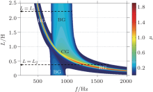
Firstly, the effects of inductances L are examined. In Fig. 5, a two-dimensional (2D) plot of the dependence of attenuation constant μ on frequency f and inductances L is shown. In Fig. 5, the colored regions characterize band-gaps, while the white regions represent pass bands, and two types of band-gaps, i.e., the resonance gap and the Bragg gap, are identified. The plot clearly displays the locations, widths, and wave attenuation performances of all the band-gaps in the frequency region considered.
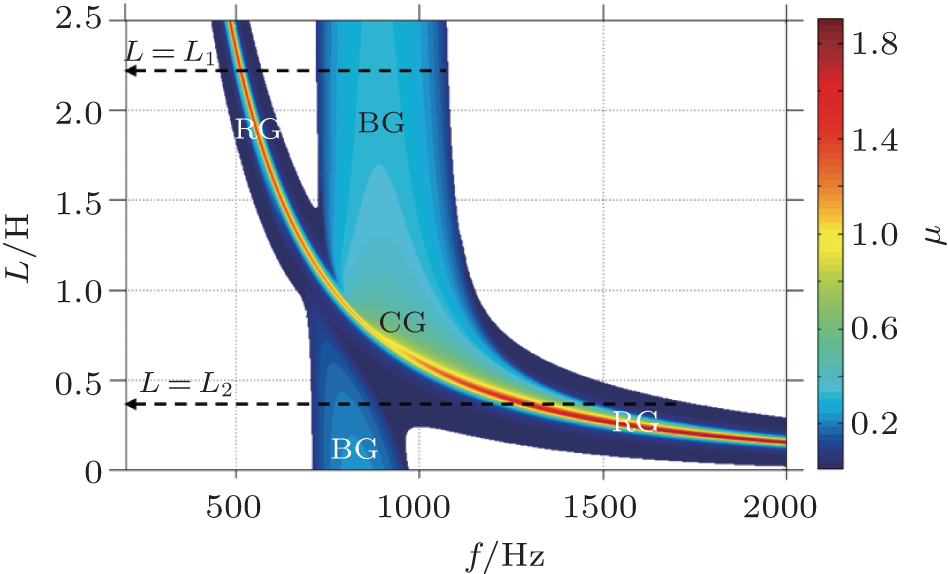 | Fig. 5. Dependence of attenuation constant μ on frequency f and inductances L. |
As can be seen in Fig. 5, when L decreases, the RG moves to a high frequency, while the lower band edge of the BG varies little. This phenomenon can be ascribed to the fact that the resonant frequency (fr) of the shunting piezoelectric patches, which relates to the RG and is given by

always increases with decreasing L, while the location of the BG is mainly associated with the lattice constant a and is independent of L.
A more interesting phenomenon occurs when the RG is tuned to a frequency around the BG. A super-wide coupled band-gap (CG) is achieved due to the coupling between RG and BG. To demonstrate this, in Fig. 5, the band-gap characteristics of two advisedly chosen systems are compared. The first system having a bigger inductance L = L1 corresponds to the case that RG and BG are not coupling, in which a RG (460– 570 Hz) and a BG (720– 1080 Hz) exist in the considered frequency range. The second system with L = L2 corresponds to the case where the coupling occurs, in which a super-wide CG (700– 1750 Hz) exists. The comparison indicates that the coupling can broaden the band-gaps significantly.
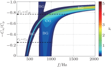
Now the effects of negative capacitances − Cn are considered. Figure 6 shows the band-gap map that indicates the dependence of attenuation constant μ on frequency f and negative capacitances − Cn.
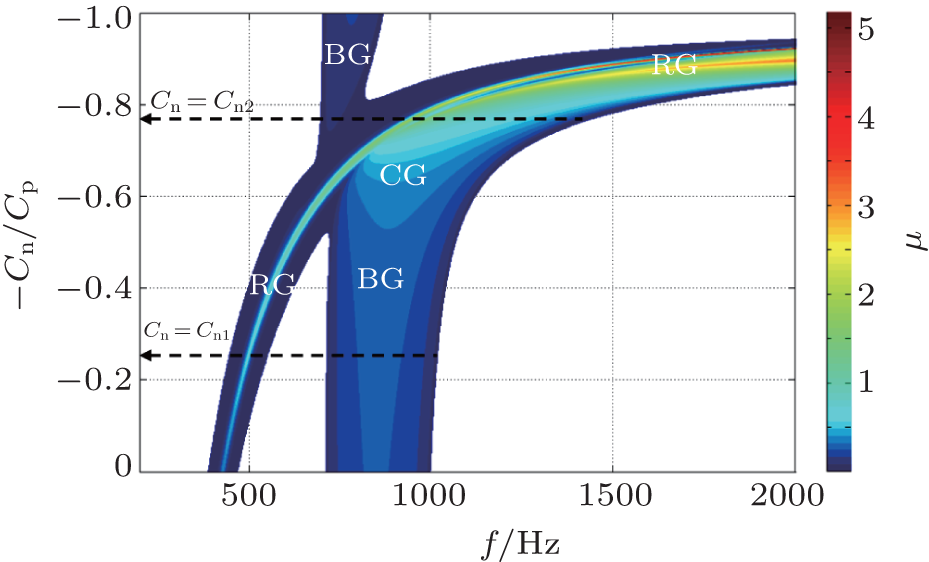 | Fig. 6. Dependence of attenuation constant μ on frequency f and negative capacitances − Cn. |
It is shown in Fig. 6 that the position of the BG still changes little with increasing − Cn, as in the former examination about the effects of L. This happens because the lattice constant a does not vary with − Cn and L. However, the RG moves to a high frequency as the absolute value of − Cn increases, which can also be explained by Eq. (11). A super-wide CG is also obtained when the coupling occurs. In a similar way to the former examination, two systems are advisedly chosen for comparison. It can be clearly seen that for the first system (− Cn = Cn1), a RG and a BG are achieved, while for the second system (− Cn = Cn2), a super-wide CG exists.
Finally, the effects of resistances R are examined. The dependence of attenuation constant μ on frequency f and resistances R is shown in Fig. 7.
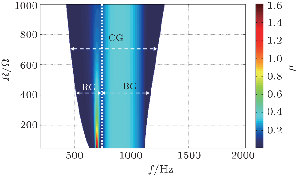 | Fig. 7. Dependence of attenuation constant μ on frequency f and resistances R. |
It is interesting to note that when R increases, the CG is broadened, which is significant to practical applications in engineering. To get more details about the effects of R on the band-gaps, the CG is divided into RG and BG by a dotted line. The effects of R on the RG and the BG can then be studied. It can be seen that the positions of both RG and BG are not changed and their widths are broadened as R increases. A difference exists between the effects on the wave attenuation performance of RG and that of BG. The attenuation constant μ of RG decreases with increasing R, while that of BG is barely influenced by R. Consequently, there should be a careful consideration on both the widths and the attenuation performances of band-gaps before the resistance R is determined in engineering applications.
We study the flexural wave band-gaps of phononic metamaterial beams, which consist of periodic arrays of hybrid-shunted piezoelectric patches bonded to the surfaces of the host beam. To predict the band-gaps, an infinite periodic model based on the transfer matrix method is applied to predict the attenuation constants of the phononic metamaterial beams. Its validity is confirmed by comparison with the vibration transmittances predicted by a finite periodic model based on the finite element method.
It is clearly demonstrated that a narrow resonant band-gap is achieved as the passive resistive-inductive shunting circuits are closed and the active negative capacitive shunting technique can broaden the Bragg band-gaps. Interestingly, when the frequency of the RG is tuned close to that of the BG, a coupling between RG and BG is observed. This coupling gives rise to a super-wide coupled band-gap, which is significant to broadband vibration reduction applications.
Moreover, the effects of three electric components in the hybrid shunting circuits, the inductances L, the negative capacitances − Cn, and the resistances R, on the band-gaps are studied by plotting the attenuation constant surfaces, which clearly displays the locations, widths, and wave attenuation performances of all of the band-gaps. Parametric influence studies are very useful for achieving broadband vibration attenuation in phononic metamaterial beams.
| 1 |
|
| 2 |
|
| 3 |
|
| 4 |
|
| 5 |
|
| 6 |
|
| 7 |
|
| 8 |
|
| 9 |
|
| 10 |
|
| 11 |
|
| 12 |
|
| 13 |
|
| 14 |
|
| 15 |
|
| 16 |
|
| 17 |
|
| 18 |
|
| 19 |
|
| 20 |
|
| 21 |
|
| 22 |
|
| 23 |
|
| 24 |
|
| 25 |
|
| 26 |
|
| 27 |
|
| 28 |
|
| 29 |
|
| 30 |
|
| 31 |
|
| 32 |
|
| 33 |
|
| 34 |
|
| 35 |
|
| 36 |
|
| 37 |
|
| 38 |
|