

A tunable magnetically insulated transmission line oscillator*
[Fan Yu-Wei† , Wang Xiao-Yu, He Liang, Zhong Hui-Huang, Zhang Jian-De]
, Wang Xiao-Yu, He Liang, Zhong Hui-Huang, Zhang Jian-De]
|
|


†Corresponding author. E-mail: fyw9108212@126.com
*Project supported by the National Natural Science Foundation of China (Grant No. 11075210) and the Special Financial Grant from the China Postdoctoral Science Foundation (Grant No. 201104761).
A tunable magnetically insulated transmission line oscillator (MILO) is put forward and simulated. When the MILO is driven by a 430 kV, 40.6 kA electron beam, high-power microwave is generated with a peak output power of 3.0 GW and frequency of 1.51 GHz, and the relevant power conversion efficiency is 17.2%. The 3-dB tunable frequency range (the relative output power is above half of the peak output power) is 2.25–0.825 GHz when the outer radius of the slow-wave structure (SWS) vanes ranges from 77 mm to 155 mm, and the 3-dB tuning bandwidth is 92%, which is sufficient for the aim of large-scale tuning and high power output.
The magnetically insulated transmission line oscillator (MILO) is a promising high power microwave (HPM) source. The advantages of the MILO include its high power output, stable operation, self-magnetic insulation, and compact configuration, which together attract the attention of many researchers. The conventional MILO covers the frequency from L-band, S-band, C-band, X-band to Ku-band.[1– 24] Increasing the output power, pulse duration, power conversion efficiency, and repetitive frequency are four major development directions for the MILO. Therefore, the research of the conventional MILO is focused on the above-mentioned development directions. In addition, in order to increase the power conversion efficiency, preliminary studies of the complex MILO and the double-band MILO have also been carried out.[6, 8, 22] However, the characteristic of the frequency tuning of the MILO has not been studied. Some researchers even thought that the MILO could not be tuned. In some special situations, frequency tuning is required. So, research on the frequency tuning of the MILO has broad application prospects and important scientific merit.
Through adjusting the cavity depth in the slow-wave structure (SWS), the tapered MILO attained a 30% frequency bandwidth in a simulation.[3] However, the paper did not give the technical project. The frequency tuning characteristic of the load-limited MILO has never been studied, which is a great pity.
In the present paper, a tunable MILO is put forward and the relevant simulation results are given. The simulation results show that the load-limited MILO works very well in the process of frequency tuning, and a 92% frequency bandwidth can be attained in the simulation, which is sufficient for the aim of broadband tuning and high power output.
The microwave frequency of the MILO is codetermined by five factors: the inner radius, the outer radius, the period, the thickness of the SWS vanes, and the radius of the cathode. Furthermore, the most decisive factor is the depth of the SWS vanes, namely, the difference between the inner and the outer radii.[25] Keeping other parameters unchanged while changing the inner radius of the SWS vanes can change the microwave frequency. However, the inner radius of the SWS vanes also affects the electromagnetic field boundary condition, the impedance, and the quality factor of the device at the same time. Consequently, the tuning bandwidth is very small. On the other hand, changing the outer radius of the SWS vanes can acquire a great tuning bandwidth while the influence on the MILO operation is very small. In conclusion, our scheme is to change the outer radius of the SWS vanes to tune the microwave frequency.
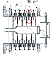
Figures 1 and 2 are schematics of the tunable MILO, and figure 3 is an enlarged drawing of part C. As shown in Figs. 1 and 2, the frequency tuning mechanism of the MILO is constructed by five flexible metal belts and eight tuners which are uniformly distributed in angle. If the tuner right above is named as the first tuner, then the following tuners are named clockwise as the second tuner to the eighth tuner respectively. Every tuner includes five restrictors, one beam, and two tuning screws. The tuning screw is inserted into the screw hole in the outer cylinder of the MILO and can be moved along the radial direction by screwing. The tuning screw has a slot in its upside. Sideways notches in the two sides of the beam can be matched into the slot of the tuning screw, which can make the beam move when the screw is turned. One side of the restrictor is a metal rod, while the other sides have two bounding boxes, known as the inner and outer bounding boxes, respectively.
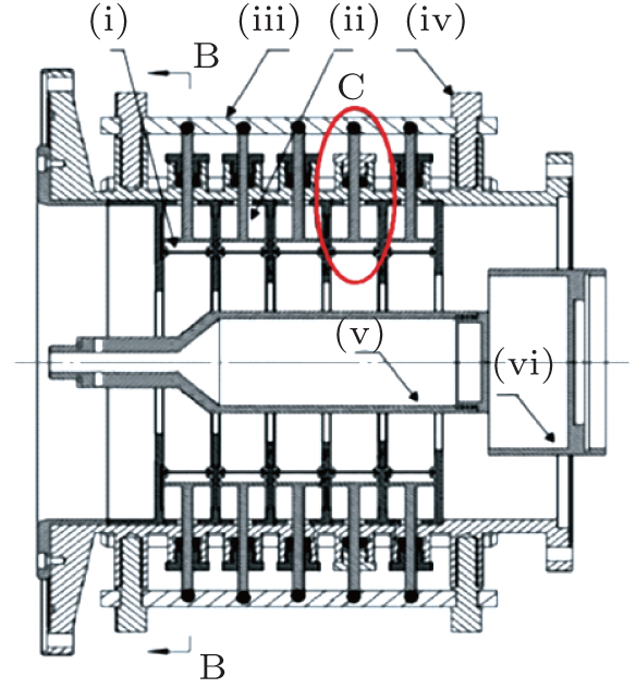 | Fig. 1. Schematic of the tunable MILO in the X– Z plane: (i) flexible metal belt, (ii) restrictor; (iii) beam, (iv) tuning screw, (v) cathode, (vi) beam dump. |
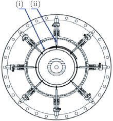
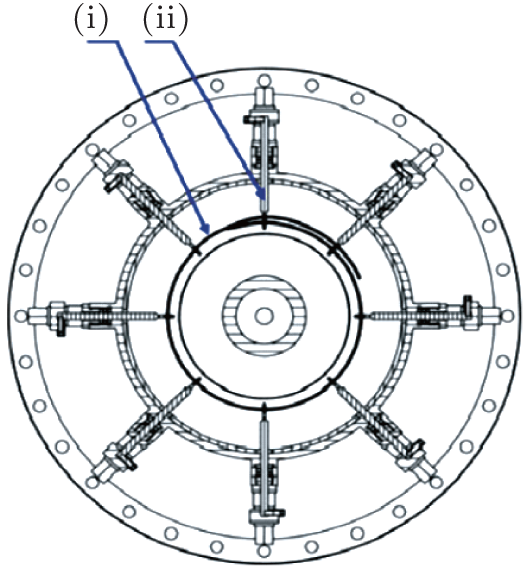 | Fig. 2. Schematic of the tunable MILO in the X– Y plane: (i) flexible metal belt, (ii) restrictor. |
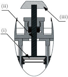
 | Fig. 3. Enlarged drawing of part C: (i) flexible metal belt, (ii) restrictor, (iii) beam. |
In Fig. 2, the heads of the flexible metal belts are fixed to the inner bounding boxes of the first group of restrictors, while the trailing ends successively enter clockwise the other seven inner bounding boxes. In the end, the flexible metal belts enter the first group of restrictors from the outer bounding boxes. In this way, the flexible metal belts can slide in the outer bounding boxes of the first group of restrictors as well as the inner and outer bounding boxes of the restrictors from the 2nd to the 7th. When the two tuning screws that are located in both ends of the same beam are screwed simultaneously, the five restrictors in the same group can move simultaneously along the radial direction. By adjusting the eight tuners to move the same distance inwards or outwards, the radius of the annulus, which is encircled by the five flexible metal belts, can be changed by the same dimension. Consequently, the microwave frequency of the MILO can be changed through mechanical adjustments. The specific adjustment is as follows.
When the tuning screws are screwed to get away from the axis of the MILO, the beams will also get away from the axis of the MILO. Thus, the bounding boxes and the flexible metal belts will get away from the axis of the MILO along with the beams. The eight tuners are far from the axis of the MILO in the same distance, which makes the radius of the annulus encircled by the flexible metal belts bigger. In the process that the bounding boxes drive the flexible metal belts to be far from the axis of the MILO, the flexible metal belts which were inserted in the outer bounding boxes previously are pulled out and slide in the bounding boxes to make up for the increases of the circumferences. The radius of the annulus is the outer radius of the SWS vanes of the MILO, so the outer radius of the SWS vanes becomes bigger. According to Ref. [2], the microwave frequency decreases along with the increase of the outer radius of the SWS vanes.
When the tuning screws are turned to be closer to the axis of the MILO, the beams will also be closer to the axis of the MILO. Thus, the bounding boxes and the flexible metal belts will be close to the axis of the MILO with the beams. The eight tuners are near the axis of the MILO at identical distances, which makes the radius of the annulus encircled by the flexible metal belts smaller. In the process that the bounding boxes drive the flexible metal belts to be close to the axis of the MILO, the flexible metal belts slide in the bounding boxes and a part of the belts are inserted in the outer bounding boxes to adapt the decreases of circumferences. The radius of the annulus is the outer radius of the SWS vanes of the MILO, so the outer radius of the SWS vanes becomes smaller. According to Ref. [2], the microwave frequency increases along with the decrease of the outer radius of the SWS vanes.
In our simulation, the applied voltage is trapezoidal, with rise time 20 ns, flat top 30 ns, and fall time 20 ns. When the typical L-band tunable MILO is driven by a 430 kV, 40.6 kA electron beam, high-power microwave is generated with an output power of 3.0 GW and frequency of 1.51 GHz, and the relevant power conversion efficiency is 17.2%. When the outer radii of the SWS vanes range from 77 mm to 155 mm, correspondingly, the range of the 3-dB frequency tuning (the relative output power is above half of the maximum output power) is from 2.25 GHz to 0.825 GHz and the 3-dB tuning bandwidth is 92%, this is sufficient for the aim of large-scale tuning and high power output.
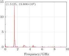
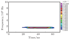
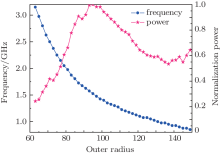
Figure 4 gives the waveform of the applied diode voltage. Figure 5 gives the output microwave power, which shows that the output power is about 3 GW and the full width at half maximum (FWHM) is 30 ns. Figure 6 gives the frequency associated with Fig. 5, which shows that the dominant frequency is 1.51 GHz. The diagram also shows that the frequency spectrum is very pure and the frequency doubling is very weak. Figure 7 gives the time-frequency analysis of the HPM, which shows that the frequency is very stable and does not change with time, which indicates that there is no mode competition. Figure 8 gives the frequency and normalized power versus the outer radius of the vane. It shows that the microwave frequency decreases monotonously when the outer radius of the vane increases monotonously. The output microwave power attains the maximum at 1.51 GHz. Moreover, the microwave frequency can reach above 3 GHz, but then the output power is lower than half of the peak output power.
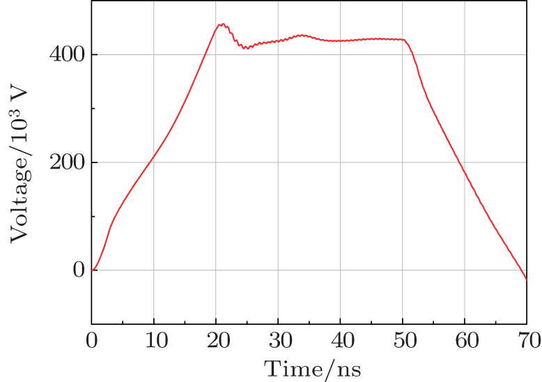 | Fig. 4. Diode voltage versus time. |
 | Fig. 5. Output power versus time. |
 | Fig. 6. Fourier spectrum of the signal. |
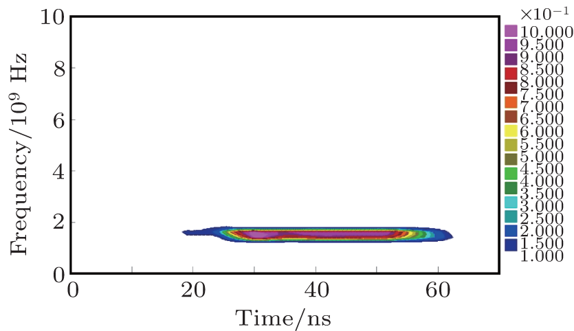 | Fig. 7. Time-frequency analysis of the HPM. |
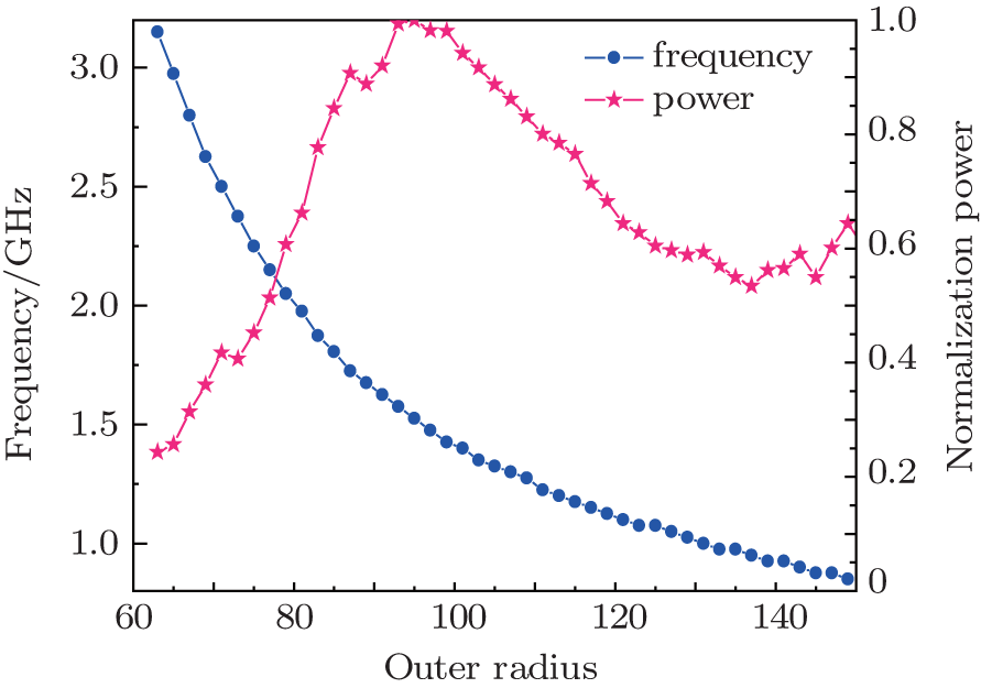 | Fig. 8. Frequency and normalized power versus outer radius of the vanes. |
A tunable MILO is put forward and simulated. The results show that when the tunable MILO is driven by a 430 kV, 40.6 kA electron beam, high-power microwave is generated with a peak output power of 3.0 GW and frequency of 1.51 GHz, and the relevant power conversion efficiency is 17.2%. The 3-dB tunable frequency range is 2.25– 0.825 GHz when the outer radius of the SWS vanes ranges from 77 mm to 155 mm, and the 3-dB tuning bandwidth is 92%, which is sufficient for the aim of large-scale tuning and high power output.
| 1 |
|
| 2 |
|
| 3 |
|
| 4 |
|
| 5 |
|
| 6 |
|
| 7 |
|
| 8 |
|
| 9 |
|
| 10 |
|
| 11 |
|
| 12 |
|
| 13 |
|
| 14 |
|
| 15 |
|
| 16 |
|
| 18 |
|
| 19 |
|
| 20 |
|
| 21 |
|
| 22 |
|
| 23 |
|
| 24 |
|
| 25 |
|
| 26 |
|