
Nonlinear properties of the lattice network-based nonlinear CRLH transmission lines*
[Wang Zheng-Bina), b)†  , Wu Zhao-Zhi
a) , Gao Chaoa) ]
, Wu Zhao-Zhi|
|


Corresponding author. E-mail: wangzb@njupt.edu.cn
Project supported by the National Natural Science Foundation of China (Grant Nos. 61201030, 60990322, and 60990320), the China Postdoctoral Science Foundation (Grant No. 2012M521048), and the Collegiate Natural Science Fund of Jiangsu Province, China (Grant No. 12KJB140010).
The nonlinear properties of lattice network-based (LNB) composite right-/left-handed transmission lines (CRLH TLs) with nonlinear capacitors are experimentally investigated. Harmonic generation, subharmonic generation, and parametric excitation are clearly observed in an unbalanced LNB CRLH TL separately. While the balanced design of the novel nonlinear TL shows that the subharmonic generation and parametric processes can be suppressed, and almost the same power level of the higher harmonics can be achieved over a wide bandwidth range, which are difficult to find in conventional CRLH TLs.
The composite right-/left-handed (CRLH) transmission line (TL), which was first introduced to mimic wave propagations in homogeneous and isotropic metamaterials in 2002, [1] has led to many novel concepts and applications.[2– 4] While in recent years, nonlinear CRLH TLs, incorporating loaded nonlinear capacitance or inductance elements with the so-called conventional CRLH TLs (shown in Fig. 1(a)), were employed as the nonlinear metamaterials to study a new class of electromagnetic phenomena, such as the harmonic generation, parametric amplification, subwavelength imaging, and solitary wave propagation.[5– 13] Such nonlinear TLs have unique characteristics including anomalous dispersion and backward wave propagation, which cause the fundamental wave to travel with its higher harmonics synchronously.[14] However, until now all of these nonlinear TL metamaterials have shared a common topology for the unit cell (as shown in Fig. 1(a)), which presents alternate left-handed (LH) and right-handed (RH) passbands, stopbands around the zeroes of the phase constant, and the poles of the series impedance/shunt admittance.[15, 16] The real part of the image impedance and the Bloch impedance of the TL model exhibit frequency-dispersive characteristics in the passbands. Therefore, conventional nonlinear CRLH TLs are not suitable for wideband operation.
Recently, a novel linear CRLH unit cell topology was proposed by Bongard et al., [16– 18] which is based on the lattice network (i.e., a circuit with crossed diagonal arms). Compared with its conventional counterpart, the lattice network-based (LNB) CRLH TL circuit has the advantage of exhibiting an all pass behavior and a frequency-independent characteristic impedance in the so-called balance case. Moreover, such a structure may also present a larger group velocity than its conventional counterpart, which is very useful for wideband application.[17, 18]
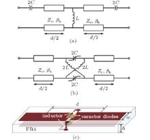
 | Fig. 1. Unit cells of (a) the conventional CRLH TL and (b) the lattice network-based nonlinear CRLH TL. (c) Schematic diagram of the fabricated lattice network-based nonlinear CRLH TL. |
In the present paper, we further introduce nonlinear capacitance into the LNB nonlinear CRLH TL (shown in Fig. 1(b)). The prototype is fabricated by parallel microstrip technology, which is shown in Fig. 1(c). Experimental measurements show that evident nonlinear phenomena occur in an unbalanced LNB nonlinear CRLH TL, such as harmonic generation, subharmonic generation, and parametric amplification. Nevertheless, when the LNB nonlinear CRLH TL is designed to be balanced, parametric processes are entirely suppressed, and almost the same power level of the higher harmonics can be achieved in a broadband spectrum. It is quite different from traditional nonlinear TLs, whether LH nonlinear TLs or RH nonlinear TLs, where the gain of higher harmonics reduces 6 dB per octave band.
As is well known, CRLH TLs, periodically cascading the unit cells shown in Fig. 1, can be characterized by their Bloch equivalents, namely the Bloch impedance ZB and the Bloch propagation constant γ B. Both of them can be deduced from the transmission matrix (or ABCD matrix) of the unit cells. The transmission matrix of the lattice network can be obtained from Ref. [15],

where

Vc is the instantaneous voltage across the series nonlinear capacitor. Then we have the Bloch impedance ZB = Z0, and the Bloch propagation constant γ B = θ /d, where d is the physical length of the unit cell. In the small signal regime, both structures in Fig. 1 can be made to be balanced (i.e., closure of the stop band between the LH and RH bands) under the same balanced condition, i.e., the characteristic impedance of the transmission line satisfies 

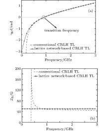
where ɛ e is the effective permittivity of the unloaded TL sections. For convenient comparison, the Bloch equivalents of the two CRLH TLs are shown in Fig. 2. Both of them are designed to be balanced, and have the same circuit parameters, which come from the element values in the following implemented TLs. Figure 2(a) shows that the Bloch impedance of the conventional CRLH TL is dispersive, while that of the LNB CRLH TL is frequency-independent. Figure 2(b) exhibits the propagation properties of the two structures and shows that the LH passband of the novel CRLH TL extends down to the dc case, while the traditional one has a Bloch cutoff frequency. Nevertheless, both of them have the same transition frequency.
For the wave propagation in LNB nonlinear CRLH TLs, we assume that the series capacitance C of the TL possesses a nonlinear voltage– charge relationship that can be expanded into a convergent Taylor series, [19, 20]

where Q(VC) is the stored charge per unit length. In order to simplify the circuit model, the losses are not considered here. Then, Kirchhoff’ s laws yield the differential equations,

where Qn and 
 | Fig. 2. Bloch equivalents for the traditional and the proposed balanced CRLH TLs with the same circuit element values (L = 20 nH, C = 8 pF, ZC = 50 Ω , ɛ r = 3.5, and d = 7.5 mm). |
Using the parallel microstrip technology, we first fabricate an unbalanced (Z0 ≠ ZC) five-section LNB nonlinear CRLH TL having the identical sections shown in Fig. 1(c). The circuit is realized on an FR4 board with permittivity ɛ r = 3.5, loss tangent tan δ = 0.025, and thickness h = 0.8 mm. The nonlinear capacitor in each section is formed by a Skyworks hyper-abrupt varactor (SMV1235), whose capacitance– voltage characteristic can be expressed as

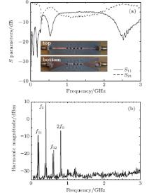
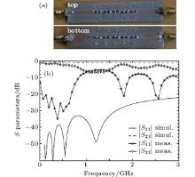
where Cj0 = 16.13 pF, Vj0 = 2.3 V, M = 4, and R = 0.6 Ω . Shunt inductors (L = 20 nH) are integrated in the parallel microstrip TL through via holes. The 2.4-mm wide parallel microstrip lines correspond to a characteristic impedance Zc = 50 Ω , and the physical length of the unit cell is d = 7.5 mm. The inset in Fig. 3(a) shows the fabricated nonlinear TL. The trapezoidal patches on the ends of the TL are used to realize impedance matching with SMA connectors. Figure 3(a) shows the measured magnitudes of the S parameters. Obviously, the nonlinear TL almost exhibits an all pass behavior except a narrow stop band around 0.3 GHz.
 | Fig. 3. (a) Measured S parameters of the unbalanced five-section LNB nonlinear CRLH TL, the inset shows the fabricated TL. (b) Spectrum of the output waveforms generated by the nonlinear TL fed by 17-dBm input signal at the fundamental frequency f0 = 0.4 GHz. |
As is well known, in RH nonlinear TLs the parametric processes are suppressed by shock-wave formation, while in LH nonlinear TLs the formation of shock waves cannot occur due to the anomalous dispersion, [14, 20] which in turn leads to a variety of parametric generations, subharmonic generations. Figure 3(b) shows that the pump wave with frequency f0 = 0.4 GHz generates not only second harmonic (2f0), but also subharmonic (f01 = f0/2) and parametric excitation (f02 = 2f0 − f01).
Then, we fabricate a balanced (Z0 = ZC) 1-section LNB nonlinear CRLH TL (shown in Fig. 4(a)), which is almost the same as that in Fig. 3(a) except the nonlinear capacitor is composed of two back-to-back varactor diodes. The capacitance– voltage characteristic of the nonlinear capacitor can be expressed as[6]

where C0 = 8 pF is the zero-bias diode capacitance, and 0 < α < 1. Under the small signal condition (linear regime), the transition frequency of the unit cell can be obtained from Eq. (2), i.e., f0 = 1.3 GHz. The measured S parameters of the unit cell are shown in Fig. 4(b), and are compared with the simulation results obtained by Agilent’ s advanced design system (ADS), where the method of moments is used. Although there are some discrepancies, which are mainly attributed to the limitations in the accuracy of the varactor diodes, the results between simulation and measurement are still in good agreement. The stop bands are notnoticeable in the S-parameters of the single cell, so the expected alternated RH and LH bands have almost balanced transitions to each other, and the LH band extends down to dc. However, when a high number of unit cells are cascaded, the residual stop bands of the all-pass TL will become evident.
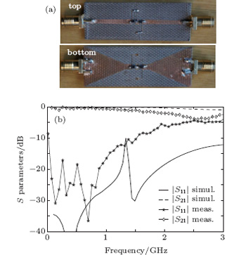 | Fig. 4. (a) Fabricated 1-section LNB nonlinear CRLH TL.(b) Measured and simulated S parameters of the single unit cell. |
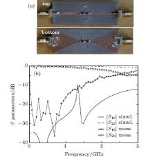
 | Fig. 5. (a) Fabricated five-section LNB nonlinear CRLH TL. (b) Measured and simulated S parameters of the single unit cell. |
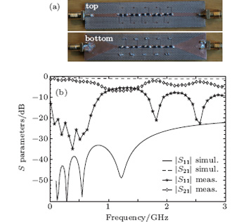
Figure 5(a) shows a five-section LNB nonlinear CRLH TL having identical sections with that in Fig. 4(a). The simulated and measured S-parameters are presented in Fig. 5(b). Due to the fact that the implemented periodic structure is not perfectly balanced (the parasitic effect and the discrepancy between the circuit model and the realistic element are unavoidable), a stop band is exhibited around the transition frequency (f0 = 1.3 GHz). Nevertheless, a transmission loss better than 5 dB is measured in other frequency bands, which includes an LH band and an RH band with a balanced LH-to-RH band transition between them.
It is well known that the nonlinear resonance in LH nonlinear TLs will result in self-induced periodicity, which in turn leads to self-induced phase-matching of the fundamental wave with its higher harmonics.[20, 21] Therefore, the combination of the non-dispersive Bloch impedance of the LNB structure with the efficient harmonic generation of nonlinear CRLH TL may improve the propagation properties of the higher harmonics. Then, we measure the spectrum of the waveform from the output of the nonlinear CRLH TL with an Agilent N5244A Spectrum Analyzer. The pump power is 20 dBm, and the active frequency ranges from 0.1 GHz to 0.8 GHz. The measured results are shown in Fig. 6. Figure 6(a) shows that a fundamental of 0.1 GHz generates the second and third harmonics with almost the same magnitudes, and it also generates the fourth and fifth harmonics with equal magnitudes. While with the increase of the fundamental frequency, the fourth and fifth harmonics disappear quickly, which should be due to the restriction of the varactors. Nevertheless, the following figures show that the second and third harmonic waves can survive, and even keep the power level unchanged in a wide band, which quite differs from general microwave transistors, where the gain of higher harmonics reduces 6 dB per octave band. This peculiarity of the novel nonlinear CRLH TL can bring favorable gain-flatness, which may lead to the development of highly efficient and powerful frequency multipliers.
 | Fig. 6. Spectra of the output waveforms generated by a five-section LNB CRLH TL fed by a 20-dBm input signal for different values of the fundamental frequency: (a) 0.1 GHz, (b) 0.4 GHz, (c) 0.5 GHz, and (d) 0.8 GHz. |
Moreover, all the measured results we have performed show no significant parametric generations, which may be due to some special mechanisms of the lattice network structure.
In this paper we demonstrate a variety of nonlinear wave phenomena in an unbalanced and a balanced LNB nonlinear CRLH TL based on parallel microstrip technology. Harmonic generation, subharmonic generation, and parametric generation are clearly observed in the unbalanced nonlinear TL. While in the balanced one, parametric processes are entirely suppressed, and higher harmonic waves with almost equal power level are observed within a broadband spectrum range, which should be due to the all-pass behavior and the less dispersive characteristic impedance of the lattice network structure. The presented prototype is a proof-of-concept. If the TL and the nonlinear capacitors are optimized, it should be able to improve the conversion efficiency of the higher harmonics. In the future, such a device could be fully implemented in monolithic microwave integrated circuits and be applied to some tunable microwave devices, [7, 22] such as frequency multipliers, tunable bandpass filters, [6] phase shifters, [7, 8] and the arbitrary waveform generator based on Fourier decomposition.[23]
| 1 |
|
| 2 |
|
| 3 |
|
| 4 |
|
| 5 |
|
| 6 |
|
| 7 |
|
| 8 |
|
| 9 |
|
| 10 |
|
| 11 |
|
| 12 |
|
| 13 |
|
| 14 |
|
| 15 |
|
| 16 |
|
| 17 |
|
| 18 |
|
| 19 |
|
| 20 |
|
| 21 |
|
| 22 |
|
| 23 |
|