


Influence of colloidal particle transfer on the quality of self-assembling colloidal photonic crystal under confined condition*
[Zhao Yong-Qiang, Li Juan, Liu Qiu-Yan, Dong Wen-Jun, Chen Ben-Yong, Li Chao-Rong† ]
]
]
|
|


Corresponding author. E-mail: crli@zstu.edu.cn
Project supported by the National Natural Science Foundation of China (Grant Nos. 91122022 and 51172209) and the Program for Changjiang Scholars and Innovative Research Team in University (PCSIRT), China (Grant No. IRT13097).
The relationship between colloidal particle transfer and the quality of colloidal photonic crystal (CPC) is investigated by comparing colloidal particle self-assembling under the vertical channel (VC) and horizontal channel (HC) conditions. Both the theoretical analyses and the experimental measurements indicate that crystal quality depends on the stability of mass transfer. For the VC, colloidal particle transfer takes place in a stable laminar flow, which is conducive to forming high-quality crystal. In contrast, it happens in an unstable turbulent flow for the HC. Crystals with cracks and an uneven surface formed under the HC condition can be seen from the images of a field emission scanning electron microscope (SEM) and a three-dimensional (3D) laser scanning microscope (LSM), respectively.
In the last few decades, colloidal photonic crystal (CPC) has gained considerable attention because of its potential far-ranging applications in a variety of fields, such as catalysis, [1, 2] sensors, [3, 4] periodic dielectric waveguides, and optical switches.[5] However, the presence of unwanted defects, such as point, line, planar defects, dislocations, and cracks in the CPC severely restrict their applications.[6] Therefore, particular efforts in two aspects have been made to gain high-quality CPC. On the one hand, many methods have been developed to produce CPC, such as gravitational sedimentation, [7] vertical deposition, [8] physical confinement, [9] assembly at the air– water interface, [10] the Langmuir– Blodgett method, [11] the template method, [12] etc. On the other hand, the growth parameters, such as temperature, pressure, concentration, solvent, and colloidal particle size[13– 15] are controlled and optimized in the formation of CPC. Although these efforts have solved some of the problems, the quality of CPC still cannot satisfy the requirements of applications in practice.
The quality of CPC can also be affected by the stability of colloidal particle transfer. As is well known, the colloidal particle transfer inevitably occurs in the process of crystal growth. The transfer process plays a substantial role in growth kinetics and determines the stability of the growth interface. Thus, the transfer is responsible for the quality of crystals. A steady mass transfer condition is crucial for obtaining high-quality crystals.[16] Although the transfer for crystal growth is a fairly active area and has become an important part of studying crystal growth, to the best of our knowledge, it has not been well investigated and understood.
Herein, we study the influences of colloidal particle transfer on the quality of CPCs under two typical transfer conditions. The vertical channel (VC) and horizontal channel (HC) acquired by photolithographic techniques are employed to create different transfer conditions. The formation mechanism for high-quality CPC is analyzed theoretically. The experimental measurements are in good agreement with the theoretical analysis.
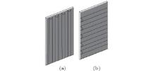
The glass substrates were employed (12 mm× 37 mm), which underwent hydrophilic processing in a piranha solution before being dried in N2. Then a photoresist layer was spin-coated on the surface of the glass substrate. Later, conventional contact photolithography was used to construct the VCs and HCs. The different channels can be seen in Fig. 1.
 | Fig. 1. Schematic illustration of (a) the VC and (b) the HC. |
An inclined deposition method was used to fabricate CPC. That is, the patterned substrates (12 mm× 37 mm) were dipped in the 10-mL beaker with 7-mL 0.08-wt% monodisperse and uniform SiO2 particles[17] (home-made with an average diameter of 373 nm and standard deviation approximately 2.61%) suspension. The inclined angle between the horizontal plane and the substrate was 60° . Then, the setups were transferred to a vacuum oven and stayed there for 16 h to evaporate the deionized water at 60-° C temperature and 85-kPa pressure. In order to investigate the growth details and optical properties, the photoresist strips were removed by soaking in acetone for 8 h.
Field emission scanning electron microscope (SEM) studies were performed with a Hitachi S-4800 microscope at an accelerating voltage of 10 kV. The optical properties of the films were investigated by an ultraviolet and visible (UV-Vis) spectrophotometer (Hitachi U-3900). The three-dimensional (3D) roughness of the surface was recorded with a 3D laser scanning microscope (LSM) (KEYENCE VK-X100K).
The formation of CPC is mainly controlled by two processes, i.e., particle transfer and particle arrangement into an ordered structure. For investigating the self-assembly of SiO2 particles, two typical setups are used as schematically shown in Fig. 2.
 | Fig. 2. Schematics of the mechanism of CPCs formed under (a) the VC condition and (b) the HC condition: 1 convection; 2 contact line; 3 glass substrate with VC; 4 glass substrate with HC. |
During the last decade, a substantial interest has been aroused in the mass transfer and crystal growth associated with the convection of the liquid phase.[18] As a common method, convection is the main method of transferring the mass and energy. For colloidal crystal growth, the effect of energy transfer can be neglected, owing to the weak interaction between particles. Hence, only the colloidal particle transfer effect induced by the convection in the process of crystal growth is discussed.
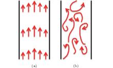
Convection in our case originates from a body force acting on a fluid in which there is a density gradient.[19] Based on fluid flow states, it can be classified as a laminar and turbulent flow. The different fluid flow states are shown in Fig. 3. In a laminar flow, the fluid flow is stable and possible to identify streamlines. In a turbulent flow, the movement of fluid flow is unsteady, irregular, and seemingly unpredictable in both space and time.[20] However, an important characteristic of the turbulent flow is its ability to transfer colloidal particles faster than the laminar flow. The transfer takes place as rapidly as possible.[21] It is noteworthy that the transition from a laminar flow to a turbulent flow can be realized by introducing artificial periodic disturbances in the direction of fluid flow deliberately.[22, 23]
 | Fig. 3. Schematic illustration of (a) laminar flow and (b) turbulent flow. |
The stability of the colloidal particle transfer effect by convection plays a key role in growing crystal. The vertical and horizontal channels present two typical transfer conditions. The VC can guide fluid flow. At the same time, they can also restrict the disordered convection (Fig. 2(a)). The net effect is that the fluid flow approximates a stable laminar flow. The colloidal particle transfer is more stable and unblocked. Thus, crystal with uniform thickness and an even surface is gained easily. However, there are periodic disturbances preventing the fluid flow under the HC condition (Fig. 2(b)). The fluid flow is unstable and finally changes into a turbulent flow. Obviously, the transfer is unstable, which will lead to defects and cracks in the crystal. In addition, the direction of cracks is perpendicular to the HC, which is due to the fact that the HC prevents the fluid flow periodically.
When the SiO2 particles are transferred to the contact line formed at the air– water– glass substrate interface, the strong attractive capillary force causes the SiO2 particles to assemble into ordered regions, which fix the contact line (Fig. 2). Then, the ordered regions grow into a large area, which is due to the further transfer of SiO2 particles caused by convection to the edge of the contact line.[14]
The plane-view SEM images of crystals formed under the VC and HC conditions are shown in Fig. 4. Crystals without forming cracks under the VC condition have been found in Figs. 4(a) and 4(b). However, plenty of cracks formed under the HC condition with a special direction, as can be seen in Figs. 4(c) and 4(d). It is obvious to note that the CPC possesses a face-centered cubic (fcc) close-packed structure with the (111) planes in Figs. 4(b) and 4(d), which is parallel to the substrate surface. The insets of fast Fourier transformed (FFT) images in Figs. 4(b) and 4(d) also show the (111) planes and higher quality of CPCs formed under the VC condition than under the HC condition.
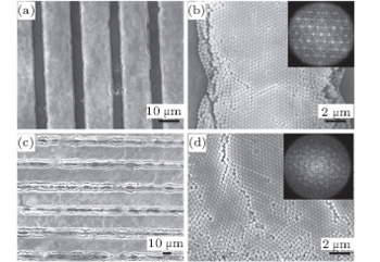 | Fig. 4. Plane-view SEM images of CPCs formed under different conditions. (a) Low-resolution and (b) high-resolution images of CPCs formed under the VC condition; (c) low-resolution and (d) high-resolution images of CPCs formed under the HC condition. The insets show the images of FFT of panels (b) and (d). |
Besides, the plane-view SEM images demonstrate that the transfer under the VC condition is easier to gain high-quality CPC than under the HC condition, which is also shown in the cross-section-view SEM images in Fig. 5. For CPC, the uniform thickness is an important factor for applications. The laminar flow formed under the VC condition is stable, so the thickness of crystal is uniform (Figs. 5(a) and 5(b)). Owing to the transfer of SiO2 particles being fast in a turbulent flow formed under the HC condition, the crystal is thicker than that in a laminar flow (Figs. 5(a) and 5(c)). Images of removing photoresist strips are shown in Figs. 5(b) and 5(d). They reveal that the structures of CPCs are not damaged in the process of soaking in acetone. Otherwise, the CPCs would collapse when the photoresist strips are removed. They also demonstrate that SiO2 particles grow first in the channels and then extensionally grow along with the formed CPCs.[24] In addition, both the VCs and the HCs are filled with SiO2 particles, but few particles are on the photoresist strips (Figs. 4(a) and 4(c)). The results also testify the order of crystal growth.
 | Fig. 5. Cross-section-view SEM images of CPCs formed under different conditions. (a) Before removing the photoresist strip image and (b) after removing the photoresist strip image of CPCs formed under the VC condition; (c) before removing the photoresist strip image and (d) after removing the photoresist strip image of CPCs formed under the HC condition. |
The examples provided in Fig. 6 for the large area (100 μ m× 141.9 μ m) show the surface features of the CPCs formed under the VC and HC conditions. The same color presents the even surface of CPC. The image (Fig. 6(b)) shows that an uneven surface in the local place has appeared on the crystal formed under the HC condition, which is due to the transfer in turbulent flow being fast but not stable. However, crystal with an even surface can be obtained under the VC condition (Fig. 6(a)).
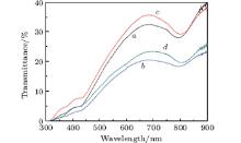
The lower transmittance value (which in Fig. 7 curve b is lower than that in Fig. 7 curve a) also illustrates that CPCs fabricated under the HC condition are thicker than under the VC condition. The fundamental stop band of CPC formed under the HCs condition should be narrower and deeper, but it is wider and shallower actually. The reason is that the turbulent flow is unstable and hence causes defects and cracks in the crystal.[25] The result also shows that the high-quality CPC can be gained under the VC condition. Figure 7 (curve a and curve b) shows a blue shift compared with removing the photoresist strips (Figs. 4(c) and 4(d)), for the refractive index of the material is changed.[26]
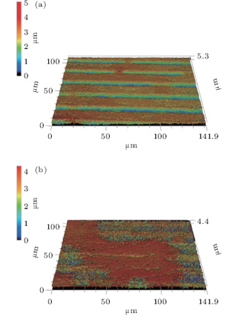 | Fig. 6. LSM images of CPCs formed under different conditions: (a) image of CPC formed under the VC condition, (b) image of CPC formed under the HC condition. |
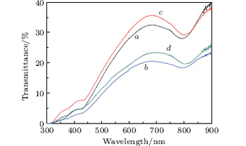 | Fig. 7. UV-Vis spectra of CPCs formed under different conditions. CPCs are formed under the VC condition, (curve a) before removing photoresist strips and (curve c) after removing photoresist strips; CPCs are formed under the HCs condition, (curve b) before removing photoresist strips and (curve d) after removing photoresist strips. |
In this paper, we investigate the effect of colloidal particle transfer on the quality of self-assembling CPC. The VC is in favor of obtaining high quality crystal via the self-assembling method, compared with the HC. The reason is that the VC provides a stabler mass transfer condition. Consequently, crystal self-assembled under the VC condition shows a higher degree in structure ordering and better performance in surface features and optical properties.
| 1 |
|
| 2 |
|
| 3 |
|
| 4 |
|
| 5 |
|
| 6 |
|
| 7 |
|
| 8 |
|
| 9 |
|
| 10 |
|
| 11 |
|
| 12 |
|
| 13 |
|
| 14 |
|
| 15 |
|
| 16 |
|
| 17 |
|
| 18 |
|
| 19 |
|
| 20 |
|
| 21 |
|
| 22 |
|
| 23 |
|
| 24 |
|
| 25 |
|
| 26 |
|