The influence of ablation products on the ablation resistance of C/C–SiC composites and the growth mechanism of SiO2 nanowires*
Li Xian-Hui, Yan Qing-Zhi†, Mi Ying-Ying, Han Yong-Jun, Wen Xin, Ge Chang-Chun‡
Institute of Nuclear and New Energy Systems Materials (Institute of Powder Metallurgy and Advanced Ceramics), University of Science and Technology Beijing, Beijing 100083, China

Corresponding author. E-mail: qzyan@ustb.edu.cn

Corresponding author. E-mail: ccge@mater.ustb.edu.cn

Project supported by the Specialized Research Fund for the Doctoral Program of Higher Education of China (Grant No. 20110006110025) and the National Natural Science Foundation of China (Grant No. U1134102).

Abstract

Ablation under oxyacetylene torch with heat flux of 4186.8 (10% kW/m2 for 20 s was performed to evaluate the ablation resistance of C/C–SiC composites fabricated by chemical vapor infiltration (CVI) combined with liquid silicon infiltration (LSI) process. The results indicated that C/C–SiC composites present a better ablation resistance than C/C composites without doped SiC. The doped SiC and the ablation products SiO2 derived from it play key roles in ablation process. Bulk quantities of SiO2 nanowires with diameter of 80 nm–150 nm and length of tens microns were observed on the surface of specimens after ablation. The growth mechanism of the SiO2 nanowires was interpreted with a developed vapor–liquid–solid (VLS) driven by the temperature gradient.

Keyword: 61.46.Km; 65.90.+i; C/C–SiC composites; ablation products; SiO2 nanowires; growth mechanism
1. Introduction

C/C– SiC composites have been successfully used as throats for solid rockets, jet vanes for thrust vector control, thrust chambers for rocket engines, and thermal protection materials in re-entry vehicles due to their superior thermal– mechanical properties and excellent ablation resistance, [1] studies on the C/C– SiC composites have been largely reported in recent years. Among these works, SiC has been attempted to introduce in the C/C composite including chemical vapor infiltration (CVI), [2, 3] chemical vapor decomposition (CVD), [4, 5] precursor infiltrations and pyrolysis (PIP), [6] slurry infiltration, [7, 8] reactive melt infiltration (RMI)[9, 10] and so on. Most of the studies about the ablation resistance of C/C– SiC composites focused on the coating types, [11] fabrication methods, [12] and morphologies of the ablated specimens[13] under oxyacetylene torch. However, there were few reports about the effect of ablation products on the ablation resistance of C/C– SiC composites, whereas they may work as a protective coating to the underlying substrate during the ablation process. Liu et al.[14] prepared the C/C– SiCC composites with layered SiC concentration microstructure by PIP combined with TCVI process. Some spherical, crown-like ablation products (SiO2 enwrapped SiC) were observed on the ablated surface, which were deemed to play key roles during the ablation process: acting as a barrier to oxidizing species attack and decreasing surface temperature of C/SiC composites. Liu et al.[9, 15] first observed SiO2 nanowires in an ablation test of ZrC– SiC coating on C/C composites under oxyacetylene torch, and discussed the growth of SiO2 nanowires by a vapor– liquid– solid (VLS) mechanism without a metal catalyst. Instead, the SiO2 nano-particles served as a growth catalyst in VLS.

In the present work, C/C– SiC composites were fabricated by chemical vapor infiltration (CVI) combined with liquid silicon infiltration (LSI) process, after ablation test with an oxyacetylene torch with heat flux of 4186.8± 10% kW/m2 for 20 s, bulk quantities of SiO2 nanowires were detected on the surfaces of the specimens. The effect on the ablation resistance of C/C– SiC composites was investigated. The growth mechanism of the SiO2 nanowires is interpreted with a developed vapor– liquid– solid (VLS) driven by the temperature gradient.

2. Experimental

In the present work, the C/C preforms of the C/C– SiC composites were fabricated by CVI process from PAN-based carbon fiber felts. The density of the C/C preform was 1.63 g/cm3. SiC was introduced into C/C composites by the method of liquid silicon infiltration (LSI) process. The temperature for the LSI process was 1450 ° C for 2 h, 1650 ° C for 1.5 h, and then 2300 ° C for 1.5 h. Then the C/C– SiC composites were prepared. The density of as-prepared composite was 1.96 g/cm3. Disk specimens (ϕ 30 mm × 10 mm) were cut from the prepared C/C– SiC composites and polished with 400-grit and 1000-grit SiC paper. For comparison, specimens of the C/C preform without SiC doped were tested under the same process conditions as the prepared C/C– SiC composites.

Ablation tests were conducted according to GJB323A-96 (National Military Standard of the People’ s Republic of China) with an oxyacetylene torch. The ablation parameters were presented in Table 1. Specimens were placed perpendicularly to the flame direction in the air. The inner diameter of the gun tip was 2 mm and the distance between the front surface of the specimens and the nozzle tip of the oxyacetylene gun was 10 mm. The ablation period was 20 s. The surface temperatures of specimens during ablation test were measured by an infrared thermometer (Raytek MR1SCSF).

Table 1. Parameters of ablation testing.

The mass and linear ablation rates were calculated by the difference of weight and thickness before and after ablation test. The final results are the average of three specimens. Morphology of prepared specimens and ablated specimens was observed by optical photograph and scanning electron microscope (SEM, JEOL JSM-6480LV). The nanowires grown on the surfaces of the specimens were characterized with field emission electron microscope (FE-SEM, ULTRA-55). Energy dispersive spectroscopy (EDS) was also performed to identify elemental compositions.

3. Results and discussion
3.1. Ablation properties of composites

Table 2 shows the ablation rates of the C/C– SiC and C/C composite specimens. The linear ablation rate of the C/C– SiC composites takes a relatively smaller improvement than that of the C/C composites (about 4/5), while the mass ablation rate of the C/C– SiC composites was much better (about 1/12) than that of the C/C composites. The correlation between linear and mass ablation rate is low because the mass ablation rate is the whole material loss of ablated specimens while linear ablation rate tells the partial thickness change of the central point on ablation specimens. Since two composites have the same basic structures, except for density difference, the doped SiC as well as the ablation products derived from it should be responsible for the difference between ablation rates of the two composites.

Table 2. Ablation rate of the C/C and C/C– SiC composite specimens.
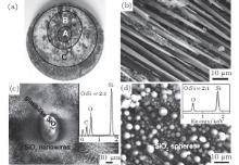
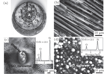
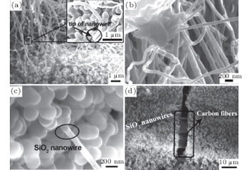
3.2. Microstructure of composites before and after ablation test

Figure 1 is the morphologies of ablated C/C– SiC composite specimens. For the convenience of discussion, the ablated surface was divided into three ring regions depending on their color and depths in Fig. 1(a). An inverted cone-shaped pit with a diameter of about 5.5 mm was formed in the ablation center, marked as A. A lot of fractured carbon fibers show a needle-like microstructure as shown in Fig. 1(b). The transition annular region oriented around the ablation center is a small downward slope with an outer diameter of about 13 mm, marked as B. Many randomly distributed white spots were detected in this region, while two distinctly different morphologies characterized as nanowires and glass-like layer were observed in Fig. 1(c). They both can be distinguished as SiO2 by an atomic ratio of O/Si in the inset EDS pattern. The outer annular region C is smooth and covered by a continuous white coating with an outer diameter of about 25 mm, lots of microspheres with a diameter ranging from 0.5 μ m to 8 μ m were observed there in Fig. 1(d), EDS inspections on microspheres showed that the atomic ratio of O/Si is about 2, which indicates that the chemical component of the microspheres is SiO2 too.

Fig. 1. Morphologies of ablated C/C– SiC composites: (a) macrograph of the ablated specimens; (b) SEM micrograph of needle-like fibers in the ablation center A; (c) SEM micrograph and EDS of SiO2 nanowires in the transition region B; and (d) SEM micrograph and EDS of SiO2 microspheres in the outer region C.

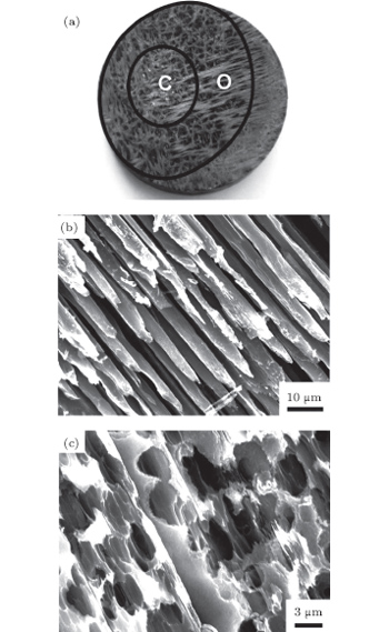
For comparison, ablation morphologies of C/C composites were also observed. Figure 2(a) is a macrograph of the ablated C/C composite specimens. The ablated surface was also divided into two regions depending on their ablation depths. An ablation pit, similar to that of the C/C– SiC composites, with a diameter of about 8 mm was formed in the ablation center, marked as C. A lot of fractured carbon fibers showed a needle-like end in Fig. 2(b). While the outer annular region (marked as O) appears a wide downward slope with an outer diameter of about 25 mm, which is about the size of sum of origin B and origin C in ablated C/C– SiC composite specimens. The carbon fibers presents apparent oxidation pits as shown in Fig. 2(c).

Fig. 2. Morphologies of C/C ablated composite specimens: (a) macrograph of the ablated specimens; (b) SEM micrograph of needle-like fibers in the ablation center region C; (c) SEM micrograph of fibers with oxidation pits in the outer annular region O.

3.3. Ablation products and ablation mechanism of composites

It has been studied that the environment under oxyacetylene torch is an oxygen-rich condition with the main components of O2, CO2, CO, and O.[16] During ablation test, the surface temperature was about 1900 ° C– 2000 ° C measured by the infrared thermometer. So all of the following reactions possibly proceeded:[4, 6, 14]

During the ablation process carbon fiber and the pyrolytic carbon by CVI were oxidized into gaseous products, while the doped SiC was oxidized into liquid SiO2 [Eq. (5)] and gaseous SiO2/SiO [Eqs. (6)– (8)], meanwhile the liquid SiO2 was likely to evaporate into gaseous SiO2 [Eqs. (9)].

The ablation center of C/C– SiC composites, where the linear ablation rate was acquired from, experienced the highest heat flux in the whole ablation process, so all those gaseous products produced violently and were taken away quickly by the high speed airflow of oxyacetylene torch. The oxidation of SiC is prior to the oxidation of carbon.[14] Hence there are only needle-like carbon fibers, without obviously generated solid products, observed in this region in Fig. 1(b). In addition, the mechanical action of high speed gas scouring also played an important role to the fracture and needle-like shape of the carbon fibers. Compared with the C/C preform without SiC doped, the doped SiC played a barrier role to oxidizing species attack into the depth, as well as the oxidation reaction and evaporation of SiO2 consume a part of oxygen and thermal energy of oxyacetylene flame. While all this benefit disappeared with the exhausting of the doped SiC so soon. Therefore, linear ablation rate of C/C– SiC composites reduced to about 4/5 of C/C composites.

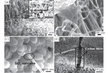
The most distinguishing characteristic in transition annular region B is the randomly distributed SiO2nanowires and glass-like layer (Fig. 1(c)). Figure 3 shows the high resolution morphology of the SiO2 nanowires. They are tens of microns in length (Fig. 3(a)) and 80 nm– 150 nm in diameter (the inset in Fig. 3(b)). It is worth noting that there is no evidence of large particles embedded in the tips of nanowires (the inset in Fig. 3(a)), which is an important characteristic of typical vapor– liquid– solid (VLS).[17, 18] For the whole C/C– SiC composites and oxyacetylene flame, there was no extra metal catalyst doped which could form an intermediate phase alloy with a lower eutectic point. So it is obvious that the conventional metal– catalytic process did not occur in this case, and it is not appropriate to interpret the growth mechanism of the SiO2 nanowires with typical vapor– liquid– solid (VLS).[19, 20]

Fig. 3. FE-SEM micrograph of SiO2 nanowires: (a) SiO2 nanowires; (b) high magnified SiO2 nanowires; (c) bonding point of SiO2 nanowires; (d) carbon fibers underlying SiO2 nanowires layer.

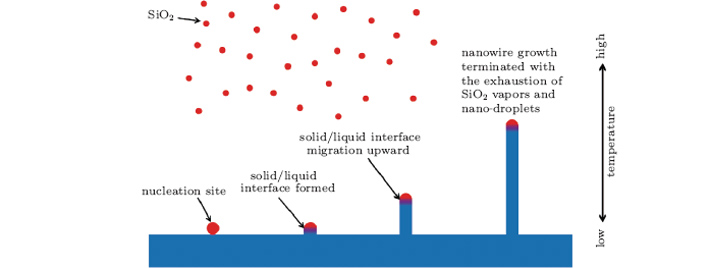
Hence, a developed vapor– liquid– solid (VLS) driven by temperature gradient was used to understand the growth mechanism of SiO2 nanowires there. Figure 4 shows a schematic diagram of the mechanism of nucleation and growth of SiO2 nanowires. As mentioned above, firstly, the doped SiC in ablation center region A and transition annular region B was oxidized into liquid SiO2 and then vapored into gaseous SiO2/SiO at the elevated temperature from oxyacetylene flame. As a physical equilibrium process, nucleation of SiO2 nanodroplets from the vapors inevitably existed. It is well known that the maximum temperature of oxyacetylene flame is above 3000 ° C, while the highest temperature of specimen surface was 1900 ° C– 2000 ° C as measured. Therefore SiO2 nano-droplets adhered on composite surface with lower temperature and formed an initial solid/liquid interface. Due to the lower temperature of composite surface, massive heat flowed away through the back surface of the specimen and water-cooled copper concave under it, solidification occurred in the lower part of the adhered SiO2 nano-droplet. While the upper part of the adhered SiO2 nano-droplet maintained liquid on account of the high temperature from oxyacetylene flame. As a result, the solid/liquid interface migration upward and SiO2 nanowires formed because the sustaining solidification from the lower location and the sustaining supply of SiO2 nano-droplet from the above vapor zone. The elongating process continued until the exhaustion of SiO2 vapors and nano-droplets. Temperature gradient served as a main driving factor in this process.

Fig. 4. Growth model of SiO2 nanowires during the ablation process.

It is noted that the carbon fibers underlying the SiO2 nanowires ablation products layer had smooth surfaces without oxidation damage (Fig. 3(d)), which suggests the formed SiO2 nanowires ablation products layer served as a protection shield for the underlying carbon fibers during the ablation process, which also proves the crack on the SiO2 nanowires ablation products layer was generated during the cooling process after ablation due to the different coefficient of thermal expansion between the SiO2 layer and composites.

Meanwhile, above the outer region, there were plenty of SiO2 vapor from local vaporation and SiO2 flow from the ablation surfaces A and B. The massive sums of spherical SiO2 nanodroplets formed for the rapid condensation of gaseous SiO2 because of a rapid temperature reduction, then nano-dropets collosioned and merged into dropets on the order of a micrometer or more, which dropped and solidified into SiO2 spherical particle on the surface of composite in a very short period (Fig. 1(d)), without a progressive solidification along the temperature gradient as nanowire in transition annular region B. Spherical SiO2 layer also served as a protection shield for the underlying carbon fibers during the ablation process. In the transition annular region and outer annular region of the ablation surface, doped SiC and the products derived from it plays a barrier role to oxidizing species attack into the depth, as well as the shared responsibility of thermal energy from oxyacetylene flame, so the C/C– SiC composites present much better mass ablation rate (about 1/12) than C/C composites.

4. Conclusions

(i) In the ablation test with an oxyacetylene torch with heat flux of 4186.8 ± 10% kW/m2 for 20 s, C/C– SiC composites fabricated by chemical vapor infiltration (CVI) combined with liquid silicon infiltration (LSI) process present better ablation resistance than C/C composites without doped SiC.

(ii) In the transition annular region and outer annular region of the ablation surface, doped SiC and the products derived from it plays a barrier role to oxidizing species attack into the depth, as well as the shared responsibility of thermal energy from oxyacetylene flame, so the C/C– SiC composites present much better mass ablation rate (about 1/12) than C/C composites.

(iii) In the ablation center, doped SiC and the products derived from it exhaust in the oxyacetylene torch test and then lose the barrier role in the late period. As a result, the linear ablation rate of the C/C– SiC composites reduced to about 4/5 of C/C composites.

(iv) Bulk quantities of SiO2 nanowires with a diameter of 80 nm– 150 nm and lengths of tens of microns were observed on the surfaces of the specimen. A developed vapor– liquid– solid (VLS) driven by the temperature gradient is proposed to interpret the growth mechanism of the SiO2 nanowires.

Reference
1 Christin F 2002 Adv. Eng. Mater. 4 903 DOI:10.1002/adem.200290001 [Cited within:1] [JCR: 1.608]
2 Yin J, Zhang H B, Xiong X, Zuo J L and Tao H J 2011 Solid State Sciences 13 2055 DOI:10.1016/j.solidstatesciences.2011.09.010 [Cited within:1] [JCR: 1.671]
3 Chen Z K, Xiong X, Li G D and Wang Y L 2009 ApSS 255 9217 DOI:10.1016/j.apsusc.2009.07.006 [Cited within:1]
4 Liu Q M, Zhang L T, Jiang F R, Liu J, Cheng L F, Li H and Wang Y G 2011 Surf. Coat. Technol. 205 4299 DOI:10.1016/j.surfcoat.2011.03.039 [Cited within:2]
5 Wang Y J, Li H J, Fu Q G, Wu H, Yao D J and Li H L 2012 Surf. Coat. Technol. 206 3883 DOI:10.1016/j.surfcoat.2012.03.039 [Cited within:1]
6 Yan B, Chen Z F, Zhu J X, Zhang J Z and Jiang Y 2009 J. Mater. Process. Technol. 209 3438 DOI:10.1016/j.jmatprotec.2008.08.002 [Cited within:2]
7 Tang S F, Deng J Y, Liu W C and Yang K 2006 Carbon 44 2877 DOI:10.1016/j.carbon.2006.06.003 [Cited within:1] [JCR: 5.868]
8 Hu P, Gui K X, Yang Y, Dong S and Zhang X H 2013 Mater. Manuf. Processes 6 1730 DOI:10.3390/ma6051730 [Cited within:1] [JCR: 1.297]
9 Li Z Q, Li H J, Li W, Wang J, Zhang S Y and Guo J 2011 ApSS 258 565 DOI:10.1016/j.apsusc.2011.08.102 [Cited within:2]
10 Li Z Q, Li H J, Zhang S Y, Wang J, Li W and Sun F J 2012 Corros. Sci. 58 12 DOI:10.1016/j.corsci.2012.01.001 [Cited within:1] [JCR: 3.615]
11 Liu L, Li H J, Shi X H, Feng W, Wang Y J and Yao D J 2013 Vacuu 90 97 DOI:10.1016/j.vacuum.2012.09.025 [Cited within:1]
12 Lee Y J and Joo H J 2004 Compos Part A-appl S 35 1285 DOI:10.1016/j.compositesa.2004.03.024 [Cited within:1] [JCR: 2.744]
13 Fang D, Chen Z F, Song Y D and Sun Z G 2009 Ceram. Int. 35 1249 DOI:10.1016/j.ceramint.2008.06.008 [Cited within:1] [JCR: 1.789]
14 Liu L, Li H J, Feng W, Shi X H, Wu H and Zhu J L 2013 Corros. Sci. 67 60 DOI:10.1016/j.corsci.2012.10.003 [Cited within:3] [JCR: 3.615]
15 Li Z Q, Li H J, Li K Z and Zhang S Y 2012 MatL 74 118 DOI:10.1063/1.4872385 [Cited within:1]
16 Shen X T, Li K Z, Li H J, Fu Q G, Li S P and Deng F 2011 Corros. Sci. 53 105 DOI:10.1016/j.corsci.2010.09.028 [Cited within:1] [JCR: 3.615]
17 Xing Y J, Y D P, Xi Z H and Xue Z Q 2002 Chin. Phys. B 11 1047 DOI:10.1088/1009-1963/11/10/015 [Cited within:1] [JCR: 1.148] [CJCR: 1.2429]
18 X L, Zhang X, Liu X L, Yan X, Cui J G, Li J S, Huang Y Q and Ren X M 2013 Chin. Phys. B 22 066101 DOI:10.1088/1674-1056/22/6/066101 [Cited within:1] [JCR: 1.148] [CJCR: 1.2429]
19 Sun S, Meng G, Zhang M and Hao Y 2003 JPCB 107 13029 DOI:10.1021/jp035763y [Cited within:1]
20 Shi W S, Peng H Y, Zheng Y F, Wang N, Shang N G, Pan Z W, Lee C S and Lee S T 2000 Adv. Mater. 12 1343 DOI:10.1002/(ISSN)1521-4095 [Cited within:1] [JCR: 14.829]