Pulsed microwave-driven argon plasma jet with distinctive plume patterns resonantly excited by surface plasmon polaritons*
Chen Zhao-Quana),b)†, Yin Zhi-Xianga)‡, Xia Guang-Qingc), Hong Ling-Lia), Hu Ye-Lina), Liu Ming-Haid), Hu Xi-Weid), Kudryavtsev A. A.b)
College of Electrical & Information Engineering, Anhui University of Science and Technology, Huainan 232001, China
Faculty of Physics, St. Petersburg State University, St. Petersburg, 198504, Russia
State Key Laboratory of Structural Analysis for Industrial Equipment, Dalian University of Technology, Dalian 116024, China
State Key Laboratory of Advanced Electromagnetic Engineering and Technology, Huazhong University of Science and Technology, Wuhan 430074, China

Corresponding author. E-mail: zqchen@aust.edu.cn

Corresponding author. E-mail: zxyin66@163.com

Project supported by the National Natural Science Foundation of China (Grant Nos. 11105002 and 61170172), the Natural Science Foundation of Anhui Province, China (Grant Nos. 1408085QA16 and 1408085ME101), the China Postdoctoral Science Foundation (Grant No. 2014M551788), and the Open-end Fund of State Key Laboratory of Advanced Electromagnetic Engineering and Technology (HUST), China (Grant No. GZ1301).

Abstract

Atmospheric lower-power pulsed microwave argon cold plasma jets are obtained by using coaxial transmission line resonators in ambient air. The plasma jet plumes are generated at the end of a metal wire placed in the middle of the dielectric tubes. The electromagnetic model analyses and simulation results suggest that the discharges are excited resonantly by the enhanced electric field of surface plasmon polaritons. Moreover, for conquering the defect of atmospheric argon filamentation discharges excited by 2.45-GHz of continued microwave, the distinctive patterns of the plasma jet plumes can be maintained by applying different gas flow rates of argon gas, frequencies of pulsed modulator, duty cycles of pulsed microwave, peak values of input microwave power, and even by using different materials of dielectric tubes. In addition, the emission spectrum, the plume temperature, and other plasma parameters are measured, which shows that the proposed pulsed microwave plasma jets can be adjusted for plasma biomedical applications.

Keyword: 52.50.Sw; 52.40.Fd; 52.35.Mw; 52.25.Os; pulsed microwave discharge; surface plasmon polaritons; atmospheric argon cold plasma jet; distinctive plasma plume patterns
1. Introduction

Although there are many types of atmospheric-pressure plasma sources, low-power microwave-driven atmospheric plasma can be generated based on the microwave resonant effect, which has several advantages over low-frequency plasmas, such as a higher density of electron and reactive species, lower plasma plume temperature, lower applied power, and longer electrode lifetime.[15] Especially for several applications, such as metal surface nitriding, medical instrument sterilization, and high-velocity fuel ignition and combustion, the atmospheric microwave plasma device has shown its potential advantages in industrial applications.[69] To further investigate the low-power microwave-driven atmospheric plasma devices, many researches have focused on optimizing the device structure for acquiring special plasma composition, plasma size, and more efficient energy absorbed by plasmas.[1014] There are four types of low-power microwave resonators: coaxial transmission line resonators (CTLR), [1] microstrip line resonators, [2] surfatron launchers, [15] and surface-wave plasma jets, [1618] which are all constructed for satisfying different application demands. The plasma jet using CTLR can yield plasma plume like a pencil tip in open air, especially the CTLR jets reported by Lee et al., [1] which are more suitable for localized three-dimensional plasma treatments. While the linear geometry plasmas can be generated by using microstrip line resonators, for example, allowing arrays composed of at least 88 elements that extend 11 cm in width, reported by Hopwood J et al., [2] which might be appropriate for use in roll-to-roll treatment of materials, etc.

For understanding the discharge mechanism of these microwave resonators, massive researches have been conducted to study the distinct characteristics of plasma plumes. Filamentation and radial contraction are found in microwave-excited argon plasmas, especially for 2.45-GHz plasma jets.[10] In 2011, we found a new type of discharge pattern called filamentary streamer discharge excited by surface waves of surface plasmon polaritons (SPPs).[3] However, the temperature of the plasma plume is higher than 600 K with a lowest input power of 20W, which is not used for biomedical applications because soft materials cannot stand heating. For reducing the temperature of the plasma plume, the pulsed input power may be an available method, of which the idea originated from other plasma sources driven by lower frequency-pulsed power supplies.[1924]

Another problem should be mentioned is that the discharge patterns of filamentation are usually present for atmospheric argon discharges excited by 2.45-GHz continued microwave. Sometimes, the discharge passages are jumped optionally, as reported in Refs. [1], [3], and [10]. Meanwhile, these filamentary discharges will change into a uniform glow discharge, when the microwave frequency is turned down to lower than 1.4 GHz.[1] In other words, an atmospheric uniform argon discharge excited by 2.45-GHz of continued microwave cannot be maintained easily by controlling the input parameters. Maybe, using a pulsed 2.45-GHz microwave or other methods (inserting a dielectric layer between electrodes) can make up for the above two flaws: hot filamentary discharge and decontrolled discharge patterns.

Recently, microwave-excited atmospheric-pressure microplasma based on CTLR has been reported by Lee et al., [1, 4] Choi et al., [11] and Kang et al.[13] They thought the discharge mechanism of their CTLR is just based on the theory of coaxial transmission line. However, the present study suggests that their theoretical method may not be used to explain the resonant discharge mechanism of our CTLR. Moreover, the factor influencing the discharge patterns and further restricting its application scope is still unclear for pulsed 2.45-GHz microwave discharge. Therefore, the purpose of this paper is to analyze the resonant discharge mechanism and obtain the distinctive plume patterns of the lower-power pulsed microwave argon cold plasma jets generated by using CTLR in ambient air. The rest of the paper is organized as follows. At first, the experimental descriptions (including experimental setup and discharge experiments) are introduced in Section 2. The resonant discharge mechanism is discussed in Section 3. The distinctive characteristics of plasma jet plumes are shown in Section 4. Finally, the conclusions are drawn in Section 5.

2. Discharge experiment description
2.1. Experimental setup

In the present study, three devices based on CTLR are constructed for the resonance frequency of 2.45-GHz microwave. The devices have a shortened end at one side and an opened end at the opposite side of the coaxial transmission lines, as shown in Fig. 1. Figure 1(a) shows the schematic plot of the whole discharge setup; figures 1(b)– 1(d) show the device photos images: (b) CTLR with a quartz tube, (c) CTLR with a quartz tube (embedded in another thicker quartz tube at open end side, just for ensuring that the gas around the tip of the metal wire is argon gas), and (d) CTLR with a plastic tube. The diameter of the inner electrode is 0.6 mm (metal wire), the inner and outer radii of the dielectric tube are 2.0 mm/3.0 mm, respectively, and the radius of the outer electrode (copper glue film) is 3 mm. The total length of each device (the length of the middle metal wire) is approximately 50 mm, and it should be noticed that this length value is not equal to one-quarter of the wavelength of the resonance frequency (about 30.6 mm for 2.45-GHz microwave). Another point should be mentioned, that the length of the outer copper film is 5 mm shorter than the length of metal wire at the open end side. The whole device has a pencil-shaped body of 6 mm in diameter. At about 20 mm to the shortened end, the CTLR is powered by an SMA connector. Argon gas is input through eight holes with about 0.2-mm diameter pricked by a stainless steel needle on copper film at the shortened end. The effect of the holes on the plasma plume characteristics is negligible because their diameters are sufficiently small in comparison with the total length of each device.[11]

Fig. 1. Schematic diagram of the whole discharge setup and the photos of three devices.

As shown in Fig. 1(a), an RF signal generator (2.4 GHz∼ 2.5 GHz, 100 mW) and a pulsed signal modulator (5-V pulsed square wave frequency: 10 Hz ∼ 200 kHz, duty cycle: 0.01 ∼ 1.00) are connected to the CTLR through a 48-dB power amplifier (continued power output adjusted from 0 W to 60 W). The forward and reflected powers are measured by RF power meters (AV23211E-100W). This pulsed microwave power supply is a solid-state power supply, which allows a rise-time of the microwave power about 10 μ s. Due to its rise-time scale, if the pulsed signal frequency is too large or the duty cycle is too small, the power output of the pulsed microwave will be unable to reach 60 W. The excitation of distinctive discharge patterns needs different applied powers, which also depends on the different pulsed frequencies and different duty cycles. This pulsed microwave power source is supplied by the Xin Sheng Communication Technology Co., Ltd. The gas flow rate is controlled by a controller (YQAR-720) and is measured by a gas flow meter (MF5700R) with a maximum flow limit of 10 standard liters per minute (slm) for argon gas. When argon gas is injected with a specific flow rate and a pulsed input microwave power with a peak power of higher than 2 W is applied to the CTLR, the argon plasma jet plume will be generated in ambient air. The discharge images are taken by a Sony digital camera at an exposure time of 100 ms. The emission spectrum is recorded by an optical emission spectrometer (AvaSpec-USB2000). The temperature of the plasma plume is measured by a temperature sensor (DS18B20, measured scope: 200 K ∼ 400 K, deviation: ± 2 K). The sensor probe does not affect the discharge formation. Unlike low-frequency plasmas, microwave-frequency plasmas are rarely affected by nearby dielectrics. However, we try to use a thermocouple (UTT02K, measured scope: – 40 ° C∼ 260 ° C, deviation ratio: ± 1.5% ) for measuring the plasma temperature, but its discharge formation is changed due to metal probe tip, and the measured temperature is about 200 ° C. The enhanced discharge (radial contraction to a lightened discharge passageway) takes place at the gap between the thermocouple probe tip and the end tip of the metal wire. This result is different from a similar work reported in Refs. [1] and [13]. The underlying physics might be studied in the future.

2.2. Distinctive performance of plasma plume patterns

At first, the discharge mechanism of the CTLR should be analyzed because the shape of the plasma plume is an important characteristic for industrial applications. The CTLR device is typically based on the transmission line to resonate at the excitation frequency. At the resonance frequency, the electric field (E field) of the standing wave becomes the maximum at the open end, where plasma can be generated.[11] For realizing a resonator, the total length of the device is chosen to be one of odd multiple numbers of quarter wavelengths: 30.6 mm, 91.8 mm, … , for 2.45-GHz microwave with a wavelength of 122.4 mm. As introduced above, the length of the proposed device is about 50 mm but not equal to the traditional resonant length, which suggests that there should exist another resonant effect. In experiments, there occur some other performances which are very different from the results reported in a similar work.[1, 1113] Therefore, before we discuss its resonant mechanism, first we present a group of discharge experiments for exhibiting the distinctive plasma plume patterns and the performances of plasma devices. Maybe we can acquire hypothesis from the discharge experiments.

Figure 2 shows a group of discharge images taken from (a) the device as shown in Fig. 1(b), (b) the device as shown in Fig. 1(c), (c) the device as shown in Fig. 1(d), (d) a plasma plume touched by a piece of glass, (e) a plasma plume near metal vernier calipers, and (f) a plasma plume touched by a human finger, respectively. In experiments, an input argon gas flow rate of 1.8 slm, applied power of 5 W, a pulsed frequency of 10 kHz, and a duty cycle of 0.1, are maintained, respectively, when making a mutual comparison of them. The plasma plumes with a length of about 10 mm, generated at the end of a metal wire, are shown in Fig. 2. It should be noticed that the plasma plume patterns present distinctive features as shown in Figs. 2(a) and 2(b). A single discharge backbone emanates from the end of the metal wire, several discharge branches originate around the discharge backbone, and each discharge bifurcates into several smaller branches. This new type of discharge pattern is named filamentary streamer discharge, [3] which has been observed in our designed plasma setup excited by surface waves of SPP.[12] However, several discharge filaments emanate from the end of the metal wire as shown in Fig. 2(c). At first, we guessed that the irregularity in Fig. 2(c) was attributed to the metal wire length extending out from the outer copper film, which is different from the quartz CTLR case; then we reconstructed another plastic CTLR with the same structure as the quartz one, but the same discharge pattern still appears. Therefore, we think this different discharge formation is due to the different dielectric tubes (quartz or plastic) used. When the plasma plumes are near to the objects (dielectric or metal), their characteristics also present different features as shown in Figs. 2(d)– 2(f). The formation of plasma plume is not changed when the plume downstream is touched by a nonconductor; but the contracted plasma plume with a steadily longer backbone located axially in the center of the plume is formed as the glowing region is near to metal vernier calipers. It seems that the metal object nearby the discharge region can enhance the jet discharge intensity. The temperature of the plasma plume, measured by a dielectric type sensor, is approximate to 310 K, while it is measured by a metal tip thermocouple to be about 200 ° C. Fortunately, most metal materials can bear the heat higher than 200 ° C, therefore the application scope is not reduced by this problem.

Fig. 2. A group of discharge images for exhibiting the distinctive discharge patterns.

3. Resonant discharge mechanism
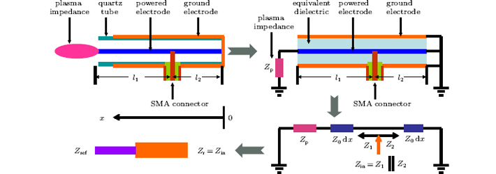
3.1. Electric model and its equivalent circuit

Here, we will use the theory of the transmission line model to further discuss the work mechanism of the proposed CTLR. The electric model and its equivalent circuit are shown in Fig. 3. It should be mentioned that the dielectric layers between the powered electrode and the ground electrode are not a single solid nor a liquid dielectric material but atmospheric gas inside the quartz tube. Hence, we use an equivalent dielectric layer instead of its actual dielectric layers, just for convenience in the simple model. The relative dielectric constant ε d for quartz tube is 3.78, and the tube wall thickness is 1.0 mm. The inner diameter of quartz tube is 4.0 mm. Hence, the relative dielectric constant ε ed ≈ 1.92 of the equivalent dielectric layer can be calculated. The CTLR is powered through a subminiature type A (SMA) connector. One side (l1 = 30.0 mm) is opened for producing the plasma plume and another side (l2 = 20.0 mm) is shortened. When the plasma plume is generated, the plasma impedance at the opened side will be Zp. Before discharge, the impedance of the opened side will be present as infinity (Zp = ∞ ). If the characteristic impedance of the coaxial transmission line in unit length equals Z0, the input impedance Zin of the CTLR is the parallel combination of an opened transmission line of length l1 connected with a plasma impedance Zp and a shortened transmission line of length l2. Based on the theory of the transmission line model, the input impedance Zin of the CTLR can be obtained as

where , α is the attenuation constant, β = 2π /λ is the phase constant of the transmission line, and k = β − jα is the complex propagation constant.

Fig. 3. Equivalent circuit of CTLR plasma jet.

Before discharge, the impedance of the opened side will be present as infinity (Zp = ∞ ), then equation (1) is in the form of

As is well known, the gas is not ionized to produce plasma until the electric field reaches a critical value of gas discharge. For the fixed gap between electrodes and in order to realize the gas discharge easily, the best choice is to make the gap of the opened side end located at a position with an odd multiple number of quarter wavelengths. As shown in Fig. 3, the voltage along the x direction will be

where Vmax is the voltage amplitude in the CTLR. The gap voltage at the opened side should be maximum, for l1 + l2 = 3λ /4,

For a given input power Pin, the voltage at the input port is given by[11]

To obtain the input power coupled to the CTLR efficiently, l2 = λ /4 should be adopted. Equation (5) shows the dependence of the input impedance in the case without plasma. Due to this relationship, the device can be matched to the power supply (Zin = 50 Ω ) during the ignition of the discharge (Zp → ∞ ). However, during normal operation (Zp has a finite value), this dependence will be broken. Other factors of fringing fields: perturbations introduced by the SMA connector and the effect of the metal tip on the resonator, also influence the position of the input port. In order to optimize the CTLR, the optimized structure can be obtained by using computer simulations.

3.2. Electromagnetic model analyses

As shown in Fig. 3, regarding the entire CTLR as a resonator, the resonator is connected with the input transmission line of characteristic impedance (Zref = 50 Ω ). The problem of excitation of the resonator is equivalent to that of an oscillator excitation. Bliokh et al.[25] and Wang et al.[26] have adopted this analogy in their theoretical model, and here, we consider a similar problem of microwave power transmission through a one-dimensional oscillator at the connected point. The transparency of this point will be characterized by transmission coefficients T (from Zref to Zin) and T′ (from Zin to Zref), [27] respectively

Therefore, is acquired.

Firstly, we consider the resonator without a pump wave. Consider an oscillator with angular eigenfrequency ω r and complex amplitude of eclectic field Er(t)∞ exp(– γ t). Here γ is the damping coefficient of the oscillation in the medium. The microwave energy stored in the resonator will be written

where N is the resonator eigenmode norm. The resonator energy loss is determined by the energy flux through the connected point from Zin to Zref and by the dissipation in the resonator. The energy flux P leaking through the connected point of the resonator is equal to

where vg is the wave group velocity. The dissipative energy loss can be expressed in the form

The energy conservation law is in the form of

Hence, the dissipation coefficient equals D = 2γ + (vg/N)T′ , and the oscillator equation is as follows:

Secondly, we consider the problem of the resonator excitation by an applied wave. When we let the incident wave amplitude be E0, the amplitude of the wave that penetrates the resonator will be . The field of this wave appears as an external force on the right-hand side of oscillator equation[25, 28]

where θ (its value is not always equal to 1) is a complex coefficient, because the phase of the field that penetrates the resonator is unknown and also the excitation efficiency of the SMA connector by this field is unknown. From Eq. (13), we have

If Zr = Zin = Zref = 50 Ω and there is no discharge (γ = 0, neglecting the energy dissipation on the transmission line, α = 0), then the complex coefficient is

In order to calculate the power reflection coefficient R, the energy conservation law is written as

It follows from Eq. (16) that

The reflection is minimal at the resonance angular frequency ω r, and further let ω = ω r. By substituting D into Eq. (17), one can obtain

Thus, the power reflection coefficient will be approximate to zero when γ = 0, Zr = Zin = Zref = 50 Ω , and T = T′ = 1. Obviously, this critical condition is not reached after the gas discharge. Another condition, like , the power reflection coefficient R also becomes zero; and thereafter

As shown in Eq. (19), considering the amplitudes of vg (about 108 ms− 1) and N, the value of γ can be estimated to range from 107 s− 1 to 108 s− 1 and further the damping time of wave energy absorbed by plasmas approximately ranges from 10 ns to 100 ns. Although the rise-time of the pulsed microwave power is about 10 μ s, there is no difficulty in absorbing the energy of resonant waves for pulsed discharge in the time scale.

From Eq. (18), the power reflection coefficient R is determined by four parameters of , vg, γ , N. For the special device structure and the applied frequency of microwave, combining Eq. (1), the reflection R is influenced mainly by two factors of the wavelength λ and the plasma impedance Zp. As introduced above, the length of the proposed device is about 50 mm but not equal to the traditional resonant wavelength. Therefore, the wavelength of the resonant wave in the CTLR should be approximate to 66.7 mm (0.75 λ ≈ 50 mm). We think this wave is the local enhanced surface wave of SPP. In theory, SPP is an electromagnetic wave that propagates along the interface between a metal and a dielectric medium. The propagation constant kspp on the dielectric– metal interface is given by[3, 25, 28]

where c is the velocity of an electromagnetic wave in a vacuum, and ε d (replaced by ε ed = 1.92 for our CTLR) are the values of relative permittivity of metal and dielectric, respectively. ω p = (e2Ne/(ε 0me))1/2 is the angular frequency of the plasma in metal, Γ is the damping rate, and Ne is the electron density of the metal. Considering ω p/Γ ≫ 1 (e.g., ω p = 1.2× 10¹⁶ rad· Hz and Γ = 1.45× 10¹³ Hz for silver in the visible frequency bands), Raether et al.[29] have given out the traditional approximation expressions below. The wavelength of SPP is given as follows:

where and are the real and imaginary parts of ε m, respectively. Therefore, for the frequency of ω = 2π × 2.45 × 109 Hz, the wavelength of SPP is about 6.4 cm for our CTLR and three quarters of the wavelength is 48 mm (not equal but close to 50 mm). We think this small difference originates from the influence of the SMA connector and the influence of the length of the metal tip being longer than the length of the outer copper film. Therefore, the wavelength scale (about 6.4 cm) is consistent with the theoretical calculating result based on SPPs, which suggests that the proposed CTLR is generated by the local enhanced electric field of the SPP. What follows is that the spatial distribution of the enhanced surface wave will be simulated by operating an electromagnetic simulation model.
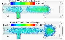
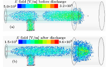
3.3. Electromagnetic simulation

In order to study the discharge mechanism of the CTLR, the electromagnetic field distribution should be simulated. We will use the HFSS simulation programs for three-dimensional numerical modeling of Maxwell equations.[13, 12, 30] The simulation is carried out by modeling the experiment device. In the simulation, the plasma electron density higher than 1.0 × 10¹⁸ m− 3 is set to be uniform and the correspondingly equivalent dielectric loss angle tangent is replaced by the energy loss due to the plasma heating through electron collision. Figure 4 shows the E field distribution in the discharge tube. Before discharge, the simulation model is without plasma and the simulated E field distributes evenly as a standing wave, which is shown in Fig. 4(a). Adding a conical plasma body (located at the end of the metal wire), the simulated E field distributed around the metal wire with sinusoidal wave peaks is obtained, and the E field distributed around the plasma is enhanced about three times, which is shown in Fig. 4(b). It should be mentioned that the maximal amplitude of the simulated E field is on the order of 106 V/m under an applied power of 3 W and its wavelength scale of about 6.4 cm, which is consistent with our previous theoretical calculation results based on SPPs.[3, 3033] These electromagnetic simulation results make one again believe that the generation mechanism of CTLR might be based on the enhanced E field of local SPPs.

Fig. 4. Simulated E fields of SPPs for the microwave plasma jet.

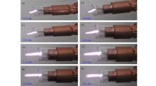
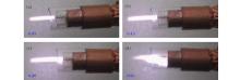
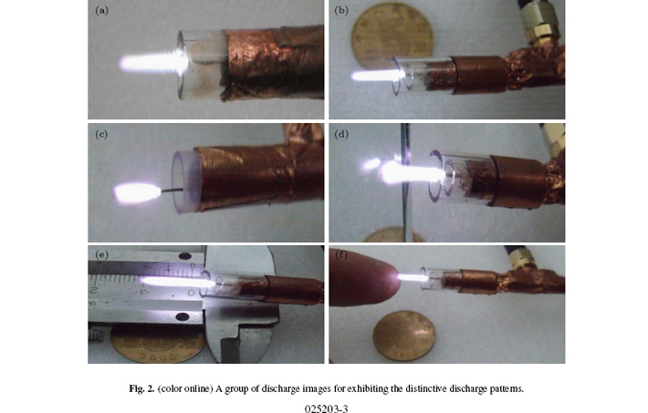
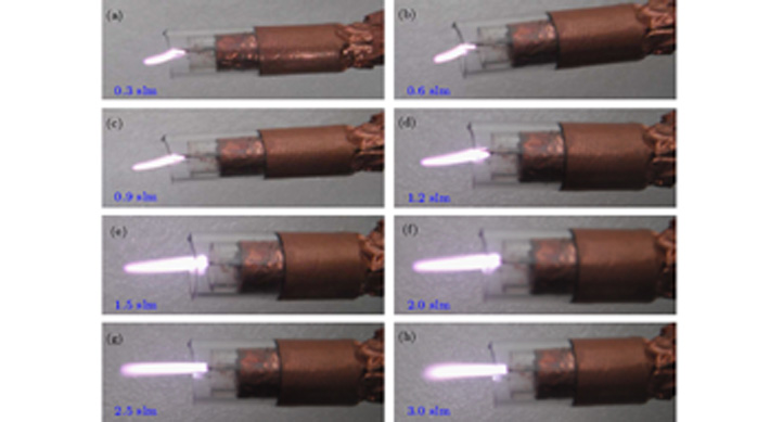
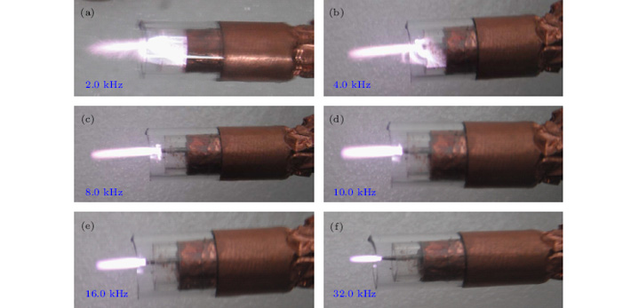
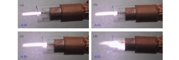
The interaction between the E field and the discharges should be another factor in the formation of an argon plasma jet plume. When the argon plasma plume is generated, the E field distribution should be changed due to the plasma bulk with a finite conductivity.[1] Therefore, the discharge process of the plasma plumes can be discussed as follows. The input microwave distributed in CTLR interacts with the metal wire and forms surface waves of SPPs around the metal wire. Surface waves of SPPs are formed as shown in Fig. 4(a). The local enhanced E field of SPPs located at the end of the metal wire accelerates the electrons to ionize the argon gas into a plasma plume. After that, increasing the density of the plasma will induce the excited wave to be reflected, thereby restricting its energy in the region near the interface and decaying through the plasma plume regions. Then, the electrons accelerated by the surface wave collide with neutral argon atoms, and the density of electrons and argon atoms in the excited state will increase simultaneously.[12] The field around the plasma plume is significantly enhanced as shown in Fig. 4(b) and is responsible for the quick elongation of the streamer in the direction of the E field.[3436] When a mass of particles in a higher energy argon excited state turns into lower energy state particles, [37] we can observe the light patterns of the filamentary streamer discharges as shown in Fig. 2 experimentally. This is the ionization developing process of the CTLR. The interaction between the plasma plume and the surface wave of SPPs results in the formation of filaments or a streamer due to discharges occurring at atmospheric pressure.[15, 1012] It should also be mentioned that the different experiments result in different types of discharge formation and different plasma plume temperatures. The different characteristics and dominant ionization processes of the argon gas could be the main reasons according to Dawson’ s theory.[34] In the following, we will present the distinctive plume patterns of CTLR experimentally.

4. Distinctive characteristics of plasma jet plumes
4.1. Discharge patterns influenced by controlling input factors

Now that the proposed plasma plumes are excited resonantly by the enhanced E field of local SPPs, the factors influencing the discharge patterns should be experimented on the CTLR. Figure 5 shows a group of discharge images with the argon gas flow rates varying from 0.3 slm to 3.0 slm, an input power of 5W, a pulsed frequency of 10 kHz, and duty cycle of 0.1. The results similar to previous ones indicate that the discharge shapes can be categorized into four phases as the gas flow increases.[1] The inner electrode and outer electrode are insulated by quartz tube for our designed CTLR, and the first two phases mentioned in Ref. [1] are expected to disappear. With the gas flow rate varying from 0.3 slm to 1.2 slm, the plasma plume bent to one side is present; the higher the gas flow, the straighter the longitudinal plasma plume becomes and the longer the glow plume will be, which is shown in Figs. 5(a)– 5(d). It should be mentioned that the plumes bend to the side in the case with larger gaps, which is different from the results in Ref. [1] but is similar to the discharge formation reported in Refs. [3] and [12], and further suggests that the discharge mechanism of our CTLR is based on SPPs. As the gas flow rate increases from 1.5 slm to 2.0 slm, the plasma plumes behave as if the filamentary streamer discharges as shown in Figs. 5(e) and 5(f). When the gas flow rate increases to higher than 2.0 slm, the shape of plasma plumes gradually changes from a conical plasma body to a cometic filament pattern, as shown in Figs. 5(g)– 5(h). Briefly summing up the above distinctive plasma plume patterns affected by the gas flow rate, we can group them into three phases: the bent plume shape, the filamentary streamer discharge, and the cometic filament pattern.

Fig. 5. A group of discharge images with the varying argon gas flow rates.

Next, because the rise-time of the pulsed microwave is about 10 μ s, the peak power output and the plasma absorbed energy that are both affected by the pulsed frequency will induce the different plasma plume patterns. Figure 6 shows a group of discharge images with the pulsed frequency changing from 2.0 kHz to 32.0 kHz, an input power of 8 W, argon gas flow rates of 1.9 slm, and a duty cycle of 0.1. As shown in Fig. 6, the higher the pulsed frequency, the shorter the duration of plasma plume. This can be explained as the effects induced by the applied power value and the electron driven time. For the 2.0-kHz case, the duty time is 50 μ s in each period, deduct the pulsed rise-time of 10 μ s, then the power peaks of 8 W will be maintained for 40 μ s. Whereas for 32.0 kHz, the duty time is 3.125 μ s in each period, take the pulsed rise-time of 10 μ s into account, the power peaks of 2.5 W can be reached but decay to 0 exponentially. In the experiment, we try to increase the pulsed frequency to about 65 kHz, the jet plasma plume starts to be extinguished; obviously, when we set a higher power value, the critical pulsed frequency can be raised correspondingly. Another distinctive point is that the filamentation discharge patterns occur at a pulsed frequency lower than 4.0 kHz, as seen from Figs. 6(a) and 6(b), which type of discharge pattern usually appears in the discharge excited by continued microwave power as reported in Refs. [1], [2], [10], and [11].

Fig. 6. A group of discharge images with different pulse frequencies.

As is well known, the plasma plume formation is mainly affected by two effects: the smaller electrons forced by E field and the larger particles (ions and neutral molecules) imparted by the gas flow. To examine the effect of the E field on discharge formation, we vary the duty cycle of the input power (8 W) and fix the other conditions (including the operating pulsed frequency of 10 kHz and the gas flow rate of 2.2 slm), because the strength of the E field is directly related to the duty cycle, in the spatiotemporal scale. Figure 7 shows a group of discharge images with the duty cycle changing from 0.05 to 0.25. With increasing the duty cycle, the applied microwave power augments, and the plasma plume grows up, but the discharge patterns all present a cometic filament pattern; this trend only takes place at a duty cycle smaller than 0.25. Once the duty cycle is raised to 0.25, the discharge pattern turns into filamentation discharge immediately, as shown in Fig. 7(d). In combination with the situation of Fig. 6(b) and the fact of rise-time about 10 μ s, if the peak power of 8 W is kept for 15 μ s (duty time of 25 μ s minus pulsed rise-time of 10 μ s), the discharge pattern changes into the filamentation discharge. If this regularity is common to all discharges, the input microwave energy of each pulse runs up to about 160 μ J (0.5× 10 μ s × 8 W+ 15 μ s × 8 W) and then the discharge formation starts to change. For proving this regularity, we experiment on the proposed CTLR with different pulsed frequencies and different duty cycles; this empirical regularity holds true for input powers higher than about 3.6 W. Due to the power supply with a maximum continuous power of 60 W and pulsed power output lower than 60 W, the up limited input power is not confirmed and the limitation of this regularity for pulsed microwave discharge still needs more verification through experiment or simulation.

Fig. 7. A group of discharge images with different duty cycles.

In short, the distinctive discharge patterns are determined mainly by four factors: the pulsed microwave power input, the enhanced E field of the local SPPs, the different gas flow rates, and the dielectric insulator between the inner electrode and the outer electrode. The pulsed microwave power input ensures that the input microwave energy lower than 160 μ J induces the filamentary streamer discharge; the enhanced E field of local SPPs makes sure the realization of lower-power microwave discharges efficiently; the different gas flow rates lead to the different chances of an argon plasma plume interacting with air; and the dielectric tube insulating the two electrodes causes the E field to be distributed in the CTLR, which is affected slightly by the plasma plume. Moreover, it is interesting to point out that the plasma plume patterns for the case of a plastic tube is different from the case of a quartz tube, which may be caused by the diffusive loss of electrons to the dielectric walls and their different accumulation capabilities of surface charges.[2224] The gas flow rate higher than 2.0 slm affecting the discharge formation can also be explained by the same effect.

4.2. Emission spectra and plume temperature measurements

Finally for checking its application scope, the plasma characteristic of the proposed CTLR should be exhibited. The various reactive species produced by the CTLR device can be measured by using optical emission spectroscopy.[2224] When the emission spectra are recorded, the input power of 5 W, the pulsed frequency of 10 kHz, the duty cycle of 0.1, the argon gas flow rate of 1.7 slm, and the operational parameter of the spectrometer, are all maintained. Figure 8 shows the emission spectra from 200 nm to 1000 nm. Excited OH, O, N2, N2+ , N2, and Ar presented in the plasma plume are shown in Fig. 8 and its inset, especially excited OH and O with larger number quantities. Therefore, this plasma plume is preferable for practical applications in plasma medicine, [4, 38] nanotechnology, and surface and materials processing, which always need the plasma glow plumes in ambient air.

Fig. 8. Emission spectra recorded from the pulsed CTLR in ambient air.

The plasma plume temperature is an important factor for biomedical applications. Because the target for treatment is contacted or located near the plasma glow, there is no damage for thermal treatment. Figure 9 shows the measured gas temperatures of the plasma plumes and the efficiencies of the pulsed CTLR. In contrast to them, their discharge conditions for Figs. 9(a)– 9(c) are the same as for Figs. 5– 7, respectively. The tip of the dielectric type sensor is contacted with the jet plasma plumes (about 2 mm away from the end of the quartz tubes). As shown in Fig. 9, the discharge patterns with a filamentary streamer discharge and a cometic filament pattern have lower temperature, about 30 ° C; while the discharge patterns with a bent plume shape and filamentation discharge have a higher temperature, even reaching about 100 ° C, as shown in Fig. 9(c). For the same discharge patterns of filamentation discharge, comparing Figs. 6(b) and 7(d) with Figs. 9(b) and 9(c) relatively, although their input microwave energy of each pulse is the same, the plasma plume temperature with a pulse frequency of 4.0 kHz is lower due to its longer plasma-off time for cooling the gas temperature. The gas temperature of the plasma plume is in a range from room temperature to about 100 ° C; in addition, the gas temperature strongly depends on the input power (or the discharge patterns). Therefore, the study of the characteristics of pulsed 2.45-GHz plasma plumes can provide helpful information about choosing which discharge input parameters will be used in each biomedical application.[3941]

Fig. 9. Plasma plume temperatures and efficiencies of CTLR device.

4.3. Efficiency, impedance, and bulk plasma density

The power output efficiency shown in Fig. 9(d) is obtained by using the peak power value measured from the forward power meter divided by the peak power value with a pulsed frequency of 2.0 kHz; the absorbed energy ratio is obtained by using the difference between the peak power values (forward power subtracts backward power) divided by the forward peak power value. Due to a duty cycle of 0.1 and a rise-time of about 10 μ s, the curve of power output efficiency versus pulse frequency is approximately a straight line. The curve value of absorbed energy ratio being close to about 0.67 brings to light that the efficiency of our proposed CTLR is stable, in spite of the different discharge conditions.

The input impedance Zin is influenced by the plasma impedance Zp as shown in Eq. (1). The plasma impedance can be estimated by fitting the calculated reflection coefficient to about 800 Ω – j350 Ω . A detailed procedure based on transmission line theory is described in the literature and the bulk plasma density can be estimated from the following equation:[1, 11, 13, 27]

where Lbulk and Abulk are the length (about 10 mm) and area (about 3.14 mm2) of the discharge, respectively, me is the electron mass, ν en is the electron collision frequency of 5.49451 × 10¹² s− 1 as shown in Ref. [1], Rp is the real part of the plasma impedance, and q is the elementary charge. Therefore, the bulk plasma density nbulk can be calculated to be about 8.3× 10²⁰ m− 3, where the density value is consistent with the values given by previous studies for argon microplasma jets in ambient air.[114, 27]

5. Conclusions

In this paper, lower-power pulsed microwave argon cold plasma jets are generated by using a CTLR in ambient air. The electromagnetic model analyses and simulation results suggest that the generation mechanism of the CTLR might be based on the enhanced E field of local SPP. The defect of atmospheric argon filamentation discharge excited by a continuous 2.45-GHz microwave can be made up by two factors: applying a dielectric tube type CTLR and driving the CTLR by using pulsed 2.45-GHz microwave. The distinctive discharge patterns are determined mainly by four factors: pulsed microwave power input, enhanced E field of local SPPs, different gas flow rates, and different dielectric tube materials. The distinctive plasma formation and its special characteristics can be obtained by controlling the discharge parameters. Owing to the very complicated interaction between jet plasma discharges and its chemical reactions with air, further work (simulation or experiment) on the discharge process of the proposed CTLR is still in progress.[42, 43]

Reference
1 Lee H W, Kang S K, Won I H, Kim H Y, Kwon H C, Sim J Y and Lee J K 2013 Phys. Plasmas 20 123506 DOI:10.1063/1.4841295 [Cited within:18] [JCR: 2.376]
2 Wu C, Hoskinson A R and Hopwood J 2011 Plasma Sources Sci. Technol. 20 045022 DOI:10.1088/0963-0252/20/4/045022 [Cited within:3]
3 Chen Z, Xia G, Zhou Q, Hu Y, Zheng X, Zheng Z, Hong L, Li P, Huang Y and Liu M 2012 Rev. Sci. Instrum. 83 084701 DOI:10.1063/1.4738779 [Cited within:7] [JCR: 1.367]
4 Lee H Wk, Lee H W, Kang S K, Kim H Y, Won I H, Jeon S M and Lee J K 2013 Plasma Sources Sci. Technol. 22 055008 DOI:10.1088/0963-0252/22/5/055008 [Cited within:2]
5 Hoskinson A R and Hopwood J 2012 Plasma Sources Sci. Technol. 21 052002 DOI:10.1088/0963-0252/21/5/052002 [Cited within:2]
6 Kim J and Terashima K 2005 Appl. Phys. Lett. 86 191504 DOI:10.1063/1.1926411 [Cited within:1] [JCR: 3.794]
7 Zhang Z and Hopwood J 2009 Appl. Phys. Lett. 95 161502 DOI:10.1063/1.3251793 [Cited within:1] [JCR: 3.794]
8 Kim J, Katsurai M, Kim D and Ohsaki H 2008 Appl. Phys. Lett. 93 191505 DOI:10.1063/1.3025841 [Cited within:1] [JCR: 3.794]
9 Xue J, Urdahl R S and Cooley J E 2012 Appl. Phys. Lett. 100 064102 DOI:10.1063/1.3681146 [Cited within:1] [JCR: 3.794]
10 Schlüter H and Shivarova A 2007 Phys. Rep. 443 121 DOI:10.1016/j.physrep.2006.12.006 [Cited within:5] [JCR: 22.929]
11 Choi J, Iza F, Do H J, Lee J K and Cho M H 2009 Plasma Sources Sci. Technol. 18 025029 DOI:10.1088/0963-0252/18/2/025029 [Cited within:7]
12 Chen Z, Liu M, Xia G and Huang Y 2012 IEEE Trans. Plasma Sci. 40 2861 DOI:10.1109/TPS.2012.2208228 [Cited within:5]
13 Kang S K, Seo Y S, Lee H W, Aman-ur-Rehman, Kim G C and Lee J K 2011 J. Phys. D: Appl. Phys. 44 435201 DOI:10.1088/0022-3727/44/43/435201 [Cited within:4] [JCR: 2.528]
14 Xue J and Hopwood J 2009 IEEE Trans. Plasma Sci. 37 816 DOI:10.1109/TPS.2009.2015453 [Cited within:2]
15 Hnilica J, Kudrle V, Vasina P, Schafer J and Aubrecht V 2012 J. Phys. D: Appl. Phys. 45 055201 DOI:10.1088/0022-3727/45/5/055201 [Cited within:1] [JCR: 2.528]
16 Esakov I I, Grachev L P, Khodataev K V, Bychkov V L and Wie D M V 2007 IEEE Trans. Plasma Sci. 35 1658 DOI:10.1109/TPS.2007.901881 [Cited within:1]
17 Takamura S, Amano S, Kurata T, Kasada H, Yamamoto J, Razzak M A, Kushida G, Ohno N and Kand o M 2011 J. Appl. Phys. 110 043301 DOI:10.1063/1.3622302 [Cited within:1] [JCR: 0.71]
18 Munoz J and Calzada M D 2008 J. Phys. D: Appl. Phys. 41 135203 DOI:10.1088/0022-3727/41/13/135203 [Cited within:1] [JCR: 2.528]
19 Hubner S, Palomares J M, Carbone E A D and van der Mullen J J A 2012 J. Phys. D: Appl. Phys. 45 055203 DOI:10.1088/0022-3727/45/5/055203 [Cited within:1] [JCR: 2.528]
20 Monfared S K, Hoskinson A R and Hopwood J 2013 J. Phys. D: Appl. Phys. 46 425201 DOI:10.1088/0022-3727/46/42/425201 [Cited within:1] [JCR: 2.528]
21 Carbone E and Nijdam S 2014 Plasma Sources Sci. Technol. 23 012001 DOI:10.1088/0963-0252/23/1/012001 [Cited within:1]
22 Lu X, Wu S, Chu P K, Liu D and Pan Y 2011 Plasma Sources Sci. Technol. 20 065009 DOI:10.1088/0963-0252/20/6/065009 [Cited within:2]
23 Chen Z, Xia G, Li P, Hong L, Hu Y, Zheng X, Wang Y, Huang Y, Zhu L and Liu M 2013 IEEE Trans. Plasma Sci. 41 1658 DOI:10.1109/TPS.2013.2262005 [Cited within:1]
24 Chen Z, Zheng X, Xia G, Li P, Hu Y, Du Z, Zhu L, Liu M, Chen M and Hu X 2014 Plasma Sci. Technol. 16 329 DOI:10.1088/1009-0630/16/4/06 [Cited within:3] [JCR: 0.514] [CJCR: 0.2265]
25 Bliokh Y P, Felsteiner J and Slutsker Y Z 2005 Phys. Rev. Lett. 95 165003 DOI:10.1103/PhysRevLett.95.165003 [Cited within:3] [JCR: 7.943]
26 Wang L, Cao J, Wang Y, Niu T, Liu L and Lv Y 2008 Chin. Phys. B 17 2257 DOI:10.1088/1674-1056/17/6/053 [Cited within:1] [JCR: 1.148] [CJCR: 1.2429]
27 Iza F and Hopwood J 2005 Plasma Sources Sci. Technol. 14 397 DOI:10.1088/0963-0252/14/2/023 [Cited within:3]
28 Chen Z, Liu M, Tang L, Lv J, Wen Y and Hu X 2009 J. Appl. Phys. 106 063304 DOI:10.1063/1.3225587 [Cited within:2] [JCR: 0.71]
29 Agranovich V M and Mills D L 1982 Surface Polaritions: Electromagnetic Waves at Surfaces and Interfaces Netherland s ElsevierChaps. 1 and 9 [Cited within:1]
30 Chen Z, Liu M, Zhou Q, Hu Y, Yang A, Zhu L and Hu X 2011 Chin. Phys. Lett. 28 045201 DOI:10.1088/0256-307X/28/4/045201 [Cited within:2] [JCR: 0.811] [CJCR: 0.4541]
31 Chen Z, Ye Q, Xia G, Hong L, Hu Y, Zheng X, Li P, Zhou Q, Hu X and Liu M 2013 Phys. Plasmas 20 033502 DOI:10.1063/1.4794736 [Cited within:1] [JCR: 2.376]
32 Xu X, Liu F, Zhou Q, Liang B, Liang Y and Liang R 2008 Appl. Phys. Lett. 92 011501 DOI:10.1063/1.2829591 [Cited within:1] [JCR: 3.794]
33 Chen Z, Liu M, Tang L, Hu P and Hu X 2009 J. Appl. Phys. 106 013314 DOI:10.1063/1.3168493 [Cited within:1] [JCR: 0.71]
34 WalshJ L, Iza F, Janson N B, Law V J and Kong M G 2010 J. Phys. D: Appl. Phys. 43 075201 DOI:10.1088/0022-3727/43/7/075201 [Cited within:2] [JCR: 2.528]
35 Boeuf J P, Chaudhury B and Zhu G 2010 Phys. Rev. Lett. 104 015002 DOI:10.1103/PhysRevLett.104.015002 [Cited within:1] [JCR: 7.943]
36 Zhu G, Boeuf J P and Li J 2012 Acta Phys. Sin. 61 235202 (in Chinese) DOI:10.7498/aps.61.235202 [Cited within:1] [JCR: 1.016] [CJCR: 1.691]
37 Chen Z, Hu D, Liu M, Xia G, Zheng X, Hu Y, Ye Q, Chen M, Zhu L and Hu X 2014 Chin. Phys. B 23 035202 DOI:10.1088/1674-1056/23/3/035202 [Cited within:1] [JCR: 1.148] [CJCR: 1.2429]
38 Zheng Z, Chen Z, Liu P, Zhou Q, Chen M, Wang G, Zhou Q, Fulcheri L and Liu M 2014 IEEE Trans. Plasma Sci. 42 911 DOI:10.1109/TPS.2013.2295837 [Cited within:1]
39 Zhou Q, Dong Z and Chen J 2011 Acta Phys. Sin. 60 125202 (in Chinese) [Cited within:1] [JCR: 1.016] [CJCR: 1.691]
40 Yang J, Shi F, Yang T and Meng Z 2010 Acta Phys. Sin. 59 8701 (in Chinese) [Cited within:1] [JCR: 1.016] [CJCR: 1.691]
41 Chen Z, Yin Z, Cheng M, Liu M, Xu G, Hu Y, Xia G, Song X, Jia X and Hu X 2014 Acta Phys. Sin. 63 095205 (in Chinese) DOI:10.7498/aps.63.095205 [Cited within:1] [JCR: 1.016] [CJCR: 1.691]
42 Zhu L, Chen Z, Yin Z, Wang G, Xia G, Hu Y, Zheng X, Zhou M, Chen M and Liu M 2014 Chin. Phys. Lett. 31 035203 DOI:10.1088/0256-307X/31/3/035203 [Cited within:1] [JCR: 0.811] [CJCR: 0.4541]
43 Chen Z, Xia G, Liu M, Zheng X, Hu Y, Li P, Xu G, Hong L, Sheng H and Hu X 2013 Acta Phys. Sin. 62 195204 (in Chinese) DOI:10.7498/aps.62.195204 [Cited within:1] [JCR: 1.016] [CJCR: 1.691]